MacDon M150 2009 Parts list manual

Double Windrow Attachmen
t
For M150 & M200 Tractors
SET-UP INSTRUCTION / OPERATOR’S MANUAL / PARTS CATALOG
January, 2009
Part #169216 $15

MACDON DOUBLE WINDROW ATTACHMENT

Form 169216 January 2009
1
MacDon M Series Windrower Tractor
DOUBLE WINDROW ATTACHMENT
TABLE OF CONTENTS
Introduction ............................................................................................................................................. 1
Set-Up Instructions .......................................................................................................................2 - 14
Operation
Safety Sign Locations........................................................................................................................ 14
Safety ................................................................................................................................................ 15
To Raise & Lower Deck..................................................................................................................... 15
Side Delivery Draper Speed.............................................................................................................. 15
Deck Angle ........................................................................................................................................ 16
Deck Height....................................................................................................................................... 17
Conditioner Forming Shield Position................................................................................................. 18
Conditioner Rolls Position ................................................................................................................. 18
Operating Recommendations............................................................................................................ 19
Maintenance/Service
Draper Tension Adjustment............................................................................................................... 20
Draper Tracking Adjustment.............................................................................................................. 20
Draper Replacement ......................................................................................................................... 21
Front Skid Adjustment ....................................................................................................................... 21
Rear Deflector Adjustment ................................................................................................................ 21
Draper Roller Maintenance ......................................................................................................... 22, 23
Lubrication......................................................................................................................................... 23
Hydraulic Schematic.......................................................................................................................... 24
Repair Parts........................................................................................................................................... 25
INTRODUCTION
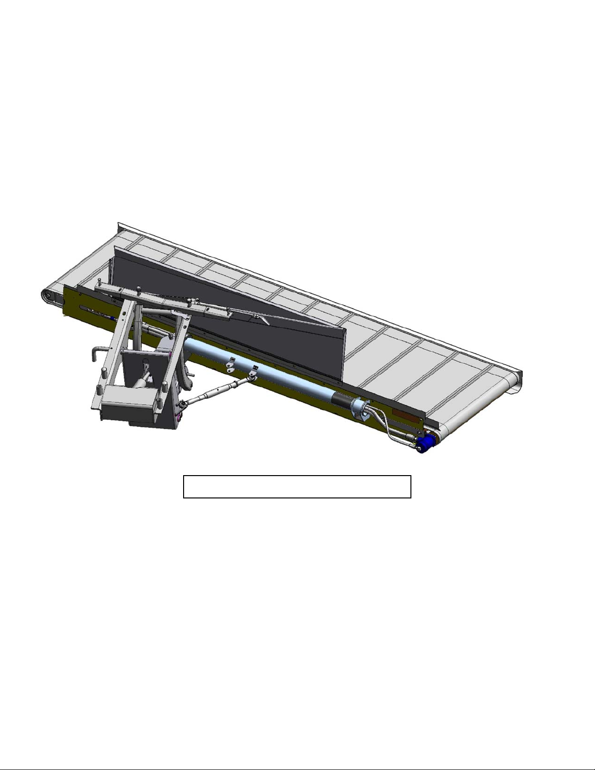
The double windrow attachment (DWA) allows the combining of two windrows of conditioned material
close together to be picked up by a forage chopper. This unit may be mounted on the following MacDon-
built windrower tractors: M150 & M200. The system is for use with Model A30, A40, R80 and D60
headers with HC10 hay conditioners. The conditioned crop is deposited onto the side delivery system
draper and delivered to the side of the tractor when required. Raising the side delivery system shuts off
the draper and allows the crop to be deposited between the tractor wheels as it would be without the side
delivery system.

SET-UP INSTRUCTIONS
Form 169216 January 2009
2
NOTE: This unit fits only the tractor models listed on page 1. It can not be installed on the M100 tractor
model.
NOTE: This page refers to rework required for tractors built prior to Production Year 2008. For tractors
built in 2008 and later, go to page 3.
On pre-2008 built tractors:
1. If not present, drill four holes 0.781” diameter at the locations shown above. There are hydraulic
hoses above the two rear holes. Make sure hoses are out of the way when drilling. Ream/grind
rear holes to make them square for square neck bolts. Slots are only required if holes do not line up
with double windrow attachment frame.

SET-UP INSTRUCTIONS
Form 169216 January 2009
3
Draper Drive Block Installation
1. Move the left cab-forward platform to the
open position for access to the hydraulic
valve blocks. Ensure the platform latch is
engaged in open position.
2. Install #12 ORB X #12 JIC fitting (A) to port
“R2” on DWA (double windrow attachment)
drive block. Install #10 ORB X #10 JIC
fitting (B) to port “P” on DWA drive block.
3. Install DWA drive block to tractor frame with
3/8” serrated flange head bolts (C). Fittings
installed earlier point towards the tractor
engine and relief valve on block points to
rear of tractor.
4. Install hose (D), supplied in kit, to fitting (A)
at DWA drive block.
A
B
A
D
E
C
Leave plastic plugs in
these two ports.
DWA DRIVE BLOCK
A
B
E
D
SUPERCHARGE PUMP
COOLER BY-PASS
RELIEF VALVE

SET-UP INSTRUCTIONS
Form 169216 January 2009
4
5. Remove hose (E) from cooler by-pass relief
valve next to oil filter and connect to fitting
(B) on DWA drive block. The other end of
hose is connected to the super charge
pump. NOTE: Access to hose (E) can be
from underneath tractor or by raising tractor
hood and working from the left hand
platform.
6. Install the other end of hose (D) to cooler by-
pass relief valve next to oil filter. This is
where hose (E) was disconnected.
Platform Rail Installation
7. Remove right hand steps (S) from platform
by loosening two top bolts (A) and removing
two bottom bolts (B). Lift steps to detach at
top keyhole slots (A). Retain bolts for next
step.
8. Install rail weldment (C) to right hand
platform as follows: Hang rail weldment (C)
by engaging keyhole slots on top bolts (A).
Install two bottom bolts (B) and tighten all
four bolts.
E
B
D
D E
A
S
B
C
A
B

SET-UP INSTRUCTIONS
Form 169216 January 2009
5
Linkage Installation
9. Remove support (A) by removing nut (B).
10. Locate in hardware kit two carriage head
bolts, 3/4 x 4-1/2” long. Install bolts (C) in
tractor frame member between the engine
and caster wheels. NOTE: Hoses will have
to be moved to get the bolts in place.
11. If mounting on an M150 tractor, proceed
with steps 12 and 13. If mounting on an
M200 tractor, go to Step 14.
12. M150: Remove the outer bolt and nut from
the front engine mount at (D) on both left
and right sides. Retain nuts for reuse.
13. M150: Mount support (A) to tractor frame
with two 1/2 x 2-3/4 inch long hex head bolts
(F), flatwashers (under bolt heads) and nuts
(E). These bolts replace the engine mount
bolts (D) removed in step 12.
- From underneath, install a 3/4 x 3-1/2 inch
long hex head bolt (G) with flat washer (H)
under bolt head. Secure with flat washer,
lock washer and nut on top side.
- From top side, install a 3/4 x 5-1/2 inch
long hex head bolt (J) with flat washer (H)
under bolt head. Do not install nut on bolt
(J).
- Go to Step 16.
B
A
C
D
F E G H F E
J
A

SET-UP INSTRUCTIONS
Form 169216 January 2009
6
14. M200: Remove four bolts (D) from the front
engine mounts, two on left side and two on
right side. Retain nuts for reuse.
15. M200: Mount support (A) to tractor frame
with four 1/2 x 2-3/4 inch long hex head
bolts (F), flatwashers (under bolt heads) and
nuts (E). These bolts replace the engine
mount bolts (D) removed in step 14. Note
that outer two bolts (F) are installed with
heads on topside and inner two bolts (F) are
installed with heads underneath.
- From underneath, install a 3/4 x 3-1/2 inch
long hex head bolt (G) with flat washer (H)
under bolt head. Secure with flat washer,
lock washer and nut on top side.
- From top side, install a 3/4 x 5-1/2 inch
long hex head bolt (J) with flat washer (H)
under bolt head. Do not install nut on bolt
(J).
16. Support linkage assembly with a forklift.
NOTE: Make sure fork is not lifting against
cylinder fitting. Align linkage with 4 bolts in
tractor frame. Mount linkage in the most
forward position (shown) if used with an R80
header and mount in the most rearward
position if used with A30/40 or D60 header.
Install four flatwashers, lock washers and
nuts at (K) and tighten
17. Lower linkage by hand by first pulling on
safety pin (M) on the LH side of linkage.
Remove plugs at end of lift cylinder hoses
(L) if needed to remove air from hoses.
D
E F
F
EF
F
J
A
G H
K
R80
A
30/40 & D60
LL
M

SET-UP INSTRUCTIONS
Form 169216 January 2009
7
18. Cylinder pivot must be in the lower hole
(shown) for A30/40 or D60 headers and
upper hole for R80 headers. Move pin to
upper hole if used with R80.
Deck Installation
19. Remove 2X4 (A) by removing banding (B)
and discard.
20. Support deck with fork lift. Forks should be
inboard of shipping stand (C). Remove two
shipping stands (C) at front deck by
removing nut (D). Discard shipping stands.
Re-install nut (D) with washer (E). Washers
are supplied in hydraulic kit.
21. Remove shipping stand (F) at rear of deck
by removing two nuts (G) and (H) and
washers (J). Discard shipping stand and
washers. Retain nuts for re-use.
22. Remove shipping stand (K) by removing
wire (L). Discard shipping stand.
23. Deck is now ready to be assembled to the
linkage underneath the tractor. Position deck
on RH side of tractor.
24. Support deck with a floor jack or fork lift at
each end and position the deck pivot (M) in
to the linkage clevis (N). Make sure there is
a loose bushing inside the deck pivot.
D
C
Fork lift
E
K
L
A
B
B
F
G
J
H
R80
A30/40 & D60

SET-UP INSTRUCTIONS
Form 169216 January 2009
8
25. Align the deck pivot with holes in clevis by
raising or lowering the floor jack and insert
shaft (P). At bottom install one regular hex
nut (H) and torque the nut to 250 ft-lbs. Then
install lock nut (G) and tighten against nut
(H). It is important that these nuts are
properly torqued. Add grease to grease
zerk (R).
26. Attach turnbuckle (Q) from linkage to deck.
Use outer pivot (shown) if used with A30/40
or D60 header and use inner pivot if used
with an R80 header.
27. Adjust turnbuckle (Q) length so the deck is
approximately 100 mm or 4” from the right
hand drive tire. The turnbuckle length
should be about 530 mm long for the R80
header and 630 mm long for the A30/40 or
D60 header. Note: The lift cylinder is single
acting and it is pressurized with the draper
drive circuit. Therefore when the deck is
setup for the R80 the tractor needs to be
running for the deck to be in its most forward
position. This adjustment can be fine-tuned
when the hydraulics setup is complete.
28. Raise backsheet (R) on deck and install gas
shock (S) in center hole with nut (T).
A
30/40 & D60
R80
Q
100 mm or 4”
S
T
R
S
T
P
H
G
M
N
R

SET-UP INSTRUCTIONS
Form 169216 January 2009
9
Hydraulics Installation
HYDRAULICS OVERVIEW
See following pages 9 to 11 for detailed installation instructions.
Balloons above match callouts on photos on pages 9 to 11.
See Maintenance/Service Section, page 22 for Hydraulic Schematic

SET-UP INSTRUCTIONS
Form 169216 January 2009
10
Hydraulics Installation (continued)
29. .Install #10 ORB X #10 JIC elbow (A) in port
“DWA” on draper drive block. Install #12
ORB X #10 JIC elbow (B) in port “R1”.
30. Install #10 tee (F) to elbow (B) as shown.
Install pressure hose (C) from draper drive
motor to elbow (A). Install return hose (D) to
tee (F). Install ½” lift cylinder hose (E) to tee
(F).
31. The installation of case drain hose (G)
depends on the header configuration. See
steps 28-31.
32. On A30/40 without reverser kit or R80
headers, connect case drain hose (G) to “T”
port on the header drive block. First connect
#12 ORB X #10 JIC elbow (H) to port “T”,
then install #10 JIC X #6 JIC reducer (J) to
elbow (H). Finally install hose (G) to reducer
(J).
33. On A30/40 headers with reverser kit,
connect case drain hose (G) to “T” port on
the header drive block. First connect #12
ORB X #10 JIC elbow (H) to port “T”, then
install #10 JIC X #10 JIC elbow (U) to elbow
(H) followed by #10 JIC X #6 JIC reducer
(J). Finally install hose (G) to reducer (J).
Make sure hose (G) is not rubbing against
any fittings.
A B
C
G
D
E
C
D
B
A
F
A
30/40 & R80
H
J
G
A
30/40 with reverser
Reverser H
U
J
G

SET-UP INSTRUCTIONS
Form 169216 January 2009
11
34. On D60 headers without reverser kit,
connect case drain hose (G) to “T” port on
the header drive block. Disconnect the reel
return hose which is connected to port “T”
and all the fittings in between. First connect
#12 ORB X #10 JIC elbow (H) to port “T”,
then install #10 JIC tee (K) to elbow (H)
followed by #10 JIC X #10 JIC elbow (U)
then #10 JIC X #6 JIC reducer (J). Finally
install hose (G) to reducer (J). Re-connect
reel return hose by first installing elbow
(which was removed earlier) to tee (K)
followed by reel return hose.
35. On D60 headers with reverser kit, connect
case drain hose (G) to “T” port on the
header drive block. Disconnect the reel
return hose which is connected to port “T”
and all the fittings in between. First connect
#12 ORB X #10 JIC elbow (H) to port “T”,
then install #10 JIC tee (K) to elbow (H)
followed by #10 JIC X #6 JIC reducer (J).
Finally install hose (G) to reducer (J). Make
sure hose (G) is not rubbing against any
fittings. Re-connect reel return hose by first
installing elbow (which was removed earlier)
to tee (K) followed by reel return hose.
D60 with reverser
Reverser H
K J
G
G
J
U
K
H
D60

SET-UP INSTRUCTIONS
Form 169216 January 2009
12
36. Remove plugs (L) and (M) from the lift
manifold block and retain.
37. Install auxiliary valve block (P) to the lift
manifold block. If installing with a D60
header with reel fore/aft, it will already have
an auxiliary valve block. The new block (P)
gets mounted next to the existing one.
Apply grease to o-rings supplied with valve
block and install them in the countersunk
port holes where the plugs were removed.
Assemble smooth side of valve (P) to lift
valve with four 3/8” bolts (N) provided. Use
the longer bolts if there are two auxiliary
valve blocks. Torque bolts to 25 ft-lbs.
38. Install #6 ORB X #6 JIC elbow (R) in to port
“K” on valve block (P). Route ¼” lift cylinder
hose (S) through side of tractor frame and
connect to elbow (R). Install plug (T) into
port “J”.
39. Neatly route the hoses by using the zip ties
that are included in the kit. Make sure
hoses are not rubbing against any moving
parts
Electrical Installation
40. Connect DWA harness from linkage to plug
(A) on the draper drive block. Connect the
other plug on DWA harness to P74 on the
tractor harness, located near the valve
block.
41. Find plug P73 on the tractor harness and
connect to plug (B) on the lift block. This is
valve “4C”. Find plug P72 and connect it to
plug (C), this is valve “2C”.
42. Inside tractor cab, remove cover (A) from
console by removing 5 screws (B).
L
M
L M
N
P
T
R
S
P
A
C
B
B
A

SET-UP INSTRUCTIONS
Form 169216 January 2009
13
43. Cut hole in decal and install rotary switch (C)
as shown. The hole is already present in the
mounting plate.
44. Remove knockout in cover (A) for rocker
switch. File down the burrs.
45. Install knob (D) on rotary switch (C).
Tighten set screw in knob with Allen wrench
(E).
46. Install rocker switch (F) in cover. The side
with the prongs should be next to the
operator’s seat.
47. Install rocker switch into plug (G) and install
rotary switch into plug (H). These plugs
come with the tractor and are inside the
console.
48. Re-install cover (A) with five screws (B).
C
D
E
F
H
G
B
A

SET-UP INSTRUCTIONS
Form 169216 January 2009
14
49. The program in the tractor monitor needs to
be changed to recognize the DWA.
a. Turn the key on. Press PROGRAM and
SELECT at the same time. Select YES
for Tractor Setup. Toggle between YES
and NO by pressing the ARROWS.
b. Scroll through the menu until display
reads “DWA INSTALLED?” and select
YES.
c. Display will then read “SWAP DWA
CONTROLS?”
d. The option exists to raise and lower the
DWA with either the reel fore/aft switch
or the rocker switch (F) installed earlier.
If YES is selected, the DWA up/down
will be controlled with the reel fore/aft
switch and reel fore/aft (D60 headers
only) will be controlled with the rocker
switch. If NO is selected, the DWA
up/down will be controlled with the
rocker switch.
e. The display will then read “EXIT DWA
MENU?” Select YES. Press
PROGRAM to revert monitor back to
operating mode.
SAFETY SIGN LOCATIONS
PART NO. 172736 – PINCH POINT
LOCATED ON LINKAGE ARM (BOTH SIDES)
PART NO. 134070 –
HIGH PRESSURE HYDRAULICS
LOCATED ON DECK
PROGRAM SELECT
ARROWS
REEL UP
REEL AFT
REEL FORWARD
REEL DOWN
DWA DOWN
DWA UP

OPERATION
Form 169216 January 2009
15
CAUTION: To avoid bodily injury:
1. Review the safety sections of your
tractor and header Operator’s Manuals.
2. Keep all shields in place.
3. Engage safety pin (A) when deck is
raised fully for transport, service and
storage or before going under deck for
any reason. To engage safety pin, raise
deck, rotate pin and push in until both
roll pins (B) are inside channel.
4. Keep away from moving draper and
rollers.
5. Keep clear of the deck while it is being
raised or lowered.
To raise and lower deck:
NOTE: Extra caution should be taken when
raising the deck for the first time. The deck
rotates as it raises and lowers and the
backsheet folds on to the deck. Make sure the
deck and backsheet are not interfering with any
tractor parts or the forming shield.
In the setup instructions, if you chose to swap
the DWA controls, use the reel fore/aft switch to
raise and lower the deck. The deck moves
forward when lowering, so switch operation will
be the same as when moving the reel forward.
The deck moves rearward when raising so
switch operation will be the same as when
moving the reel rearward.
In the setup instructions, if you chose “NO” to
swap the DWA controls, use the rocker switch
installed in the console. Press the rocker switch
forward portion to lower the DWA and press the
rocker switch rearward portion to raise the DWA.
NOTE: Draper shuts off automatically when
deck is raised about two thirds of the way up. If
deck does not shut off soon enough, resulting in
backsheet touching draper before it shuts off,
the switch at the linkage needs to be lowered.
Lower switch by loosening two screws (C). Do
not over tighten the screws or the switch will not
work.
Side delivery draper speed:
To set the draper speed, turn the draper speed
control.
AB
SAFETY PIN
DWA DOWN
DWA UP
DECK LIFT CONTROLS
DWA DOWN
DRAPER SPEED
C
DRAPER SHUT-OFF SWITCH

OPERATION
Form 169216 January 2009
16
To adjust deck angle:
The deck angle relative to the right hand drive
tire is adjustable with turnbuckle (Q). A distance
of 100 mm (4”) from the deck to the tire is
recommended. To adjust the turnbuckle, loosen
the locking tab and rotate center tube to desired
length then re-lock tab against tube.
NOTE: If setup with an R80 header, the deck
will only be in its most forward position when the
tractor is running. The lift cylinder is single
acting so it is not pressurized in the down stroke
when the tractor is shut off. When the tractor is
running there is a supply of low pressure oil to
move the deck forward.
The deck angle relative to the ground should be
horizontal or at a slight incline. Distance (C)
should be equal to or greater than (D). If used
with an R80 header in lighter crop, distance (C)
should be equal to (D). If the crop needs to be
thrown farther, increase distance (C).
To adjust the deck angle loosen four ¾” bolts (E)
and then loosen nut (F). Adjust draw bolt by
tightening the second nut (F) if you want to
increase distance (C) and loosen nut if you want
to decrease distance (C). Once done adjusting,
tighten nut (F) and then tighten four bolts (E).
The four ¾” bolts must be torqued to 245 ft-lbs.
100 mm or 4”
DECK ANGLE TO GROUND
CD
A
30/40 & D60
R80
Q
DECK ANGLE TO TIRE
E
E
F

OPERATION
Form 169216 January 2009
17
To adjust deck height:
The deck should never touch the ground or
excessive wear could occur to some deck
components. If the deck is too low to the ground,
raise it as follows:
Lower linkage by fully extending
cylinder.
Move bottom pivot pin to lower position
(R).
This will raise the front of the deck
approximately 100 mm (4 inches).
Draper tracking:
Draper tracking needs to be checked when the
draper is first run-up otherwise damage to the
draper can occur. See Draper Adjustment in the
Maintenance/Service section on how to adjust
the tracking.
R

OPERATION
Form 169216 January 2009
18
Conditioner Forming Shield Position:
Make sure forming shield is high enough to clear
the deck when it is lowered (G). Adjust the
forming shield height by removing hair pin (J)
and moving strap (K) to desired position. The
forming shield should be as low as possible
without interfering with deck.
The left hand side deflector (L) should be in the
widest position to not affect crop flow. If center
delivering, the left hand deflector can be moved
in to make a narrower windrow. The right hand
side deflector should be in the widest position to
not affect the crop flow because this is where
the deck is the furthest from the conditioner rolls.
Adjust rear deflector baffle (H) so the crop flow
does not interfere with the deck when it is fully
raised.
Fins (M) underneath the forming shield can
affect the crop flow. It is recommended to
remove fins, especially with an R80 in light crop.
Conditioner Rolls Position:
The gap between the conditioner rolls needs to
be small enough to properly throw the crop on to
the double windrow attachment. The gap is
dependant on crop type and yield. If the gap is
too little for heavy crops, this consumes
excessive engine power and is hard on all the
components affected. If the gap is too large, the
crop will not have enough velocity to reach the
side delivery deck. See conditioner operator’s
manual for adjustment procedure.
K
J
DECK RAISED
Crop Flow
H
DECK LOWERED
G
L
LL
M
This manual suits for next models
1
Table of contents
Other MacDon Tractor manuals

MacDon
MacDon M105 User manual

MacDon
MacDon M2170NT User manual

MacDon
MacDon M150 User manual

MacDon
MacDon 9250 User manual

MacDon
MacDon M155E4 2016 User manual

MacDon
MacDon M205 User manual

MacDon
MacDon M155 User manual

MacDon
MacDon M1170 User manual

MacDon
MacDon M150 User manual

MacDon
MacDon M Series User manual