manuals.online logo
Brands
  1. Home
  2. •
  3. Brands
  4. •
  5. Case IH
  6. •
  7. Tractor
  8. •
  9. Case IH JX Series User manual

Case IH JX Series User manual

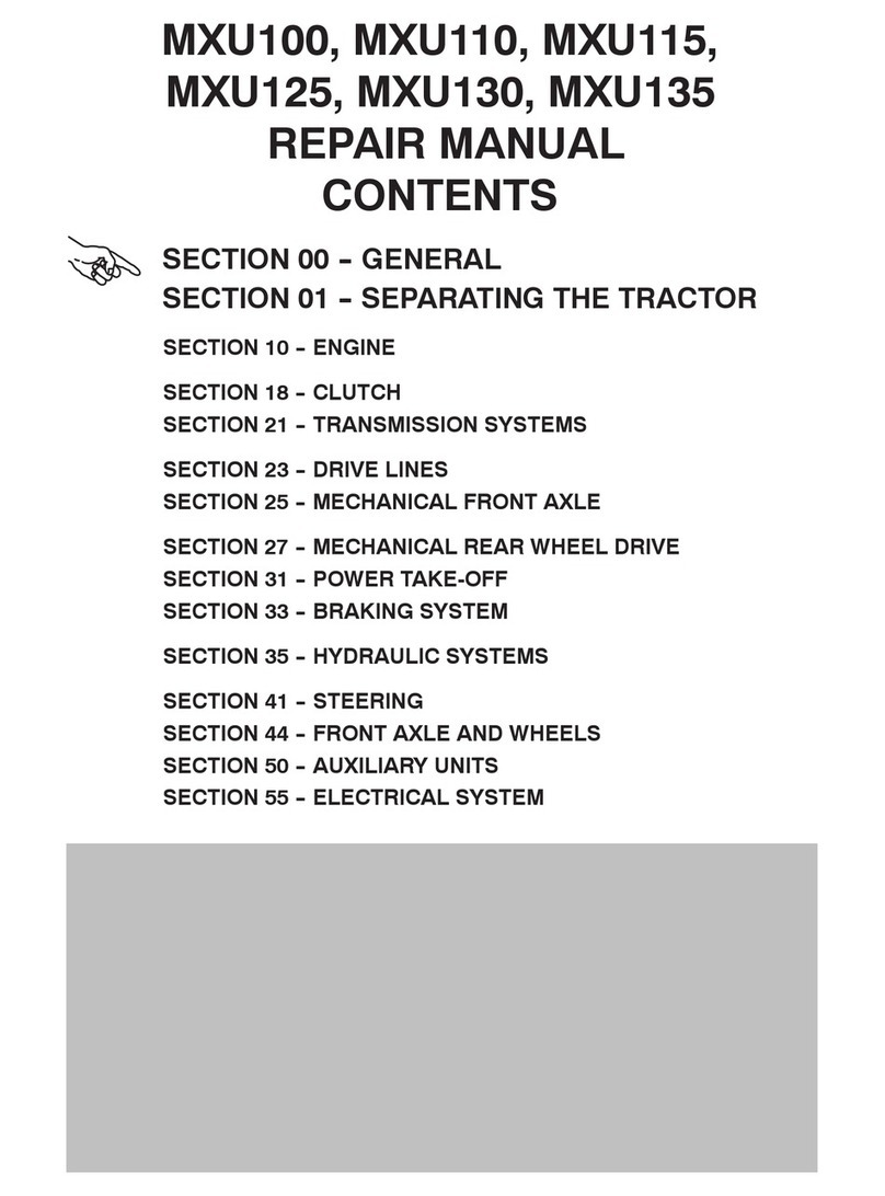
JX60 -- JX70 -- JX80 -- JX90 -- JX95
MODEL TRACTORS
SERVICE MANUAL
SECTIONS
GENERAL 00.....................................................
ENGINE 10.......................................................
CLUTCH 18.......................................................
GEARBOX 21.....................................................
TRANSMISSION OF MOTION 23....................................
FRONT MECHANICAL TRANSMISSION 25..........................
REAR MECHANICAL TRANSMISSION 27............................
POWER TAKE- OFF 31.............................................
BRAKES 33.......................................................
HYDRAULIC SYSTEMS 35.........................................
STEERING 41.....................................................
AXLE AND WHEELS 44............................................
AUXILIARY EQUIPMENT 50........................................
ELECTRICAL SYSTEM 55..........................................
CAB 90...........................................................
SERVICE
1
Repair Manual -- JX Series Tractors
CONTENTS
GENERAL SECTION 00
General Instructions and Health and Safety Chapter 1
Section Description Page
00 000 General instructions 1............................................................
Notes for spare parts 2...........................................................
Notes for equipment 2............................................................
Safety rules 3...................................................................
Consumables 6..................................................................
ENGINE SECTION 10
Engine System Chapter 1
Section Description Page
10 000 General specification 2...........................................................
Injection pump calibration data 5...................................................
General specifications 16........................................................
Tightening torques 24...........................................................
Tools 25.......................................................................
Cross--sectional views 28........................................................
Lubrication and cooling system diagrams 32........................................
Fault diagnosis 35..............................................................
10 001 10 Engine Removal--Installation 39...................................................
10 001 54 Engine Bench overhaul 53.......................................................
Checks, measurements and repairs 78............................................
10 406 10 Radiator Removal--Installation 102................................................
10 102 70 Crankshaft front oil seal removal installation 106....................................
10 402 10 Coolant pump removal installation 112.............................................
10 402 30 Cooling system thermostat 115...................................................
10 206 14 Bosch injection pump removal installation 118......................................
Bosch injection pump timing 121..................................................
Bosch injection pump air bleeding 123.............................................
10 218 30 Injectors removal installation 124..................................................
10 106 12 Valve clearance adjustment 126..................................................
3
10 402 28 Coolant pump overhaul 129......................................................
10 001 30 Compression test 130...........................................................
CLUTCH SECTION 18
Clutches Chapter 1
Section Description Page
18 000 General specifications 1..........................................................
Tightening torques 2.............................................................
Tools 3.........................................................................
Cross--sectional views 4..........................................................
Clutch Troubleshooting 5.........................................................
18 110 10 Removal -- Installation 6..........................................................
Overhaul 14....................................................................
Minimum permissible dimensions after refacing 18..................................
Adjustments 19................................................................
18 100 40 Adjustment of the main and PTO clutch control linkage 21............................
GEARBOX SECTION 21
Mechanical Transmission (12x4) Chapter 1
Section Description Page
21 000 Main data 1.....................................................................
Tightening torques 2.............................................................
Tools 3.........................................................................
Section views 3&5...............................................................
Description and operation 8.......................................................
Fault diagnosis 8................................................................
21 110 Removal -- Refitting see sect 27..................................................
Reverser (12x12) Chapter 2
Section Description Page
21 000 Main data 1.....................................................................
Tightening torques 2.............................................................
Tools 3.........................................................................
Section views 3..................................................................
Description and operation 5.......................................................
Fault diagnosis 5................................................................
21 110 Removal--Refitting 6.............................................................
Reverser and Creeper (20x12) Chapter 3
Section Description Page
21 000 Main data 1.....................................................................
Tightening torques 2.............................................................
Tools 3.........................................................................
Section views 4..................................................................
4
Description and operation 6.......................................................
Fault diagnosis 6................................................................
21 110 Removal--Refitting 7.............................................................
DRIVE LINES SECTION 23
Drive Lines Chapter 1
Section Description Page
23 000 Main specification 1..............................................................
Torque settings and Tools 2.......................................................
Cross--Sectional views 3..........................................................
23 101 26 Transmission shafts and guard (Disassembly -- Assembly) 4...........................
23 101 40 Drive gear housing (Removal -- Installation) 5........................................
23 101 42 Drive gear housing removed (Disassembly -- Assembly) 7.............................
FRONT AXLE MECHANICAL TRANSMISSION SECTION 25
Front Axle Mechanical Transmission Chapter 1
Section Description Page
25 000 Main data 1.....................................................................
Tightening torques 4.............................................................
Tools 6.........................................................................
Cross--sectional views 7..........................................................
Description and operation 9.......................................................
25 100 30 Complete front axle. Removal -- Installation 10.....................................
25 100 38 Front axle. Removal -- Installation 14..............................................
25 108 46--47 Steering knuckle bearing pins. Replacement 24....................................
Stub axle adjustment 25.........................................................
Wheel hub bearing adjustment 27.................................................
Bevel drive adjustment 29........................................................
25 102 24 Front axle differential. Overhaul 36................................................
25 100 27 Front axle differential with LIM--SLIP. Overhaul 37...................................
Front axle differential with NO SPIN. Overhaul 39...................................
44 511 80 Leading drive wheels toe--in check 42.............................................
REAR AXLE AND TRANSMISSION SECTION 27
Rear Axle And Transmission Chapter 1
Section Description Page
27 000 Main data 1.....................................................................
Tightening torques 3.............................................................
Special tools 5..................................................................
Cross--sectional views 7..........................................................
Description and operation and troubleshooting 9.....................................
5
21.118.10 -- 12 Transmission--gearbox casing Removal--Installation 10..............................
21.118.85 Transmission--gearbox casing Disassembly--Overhaul 27............................
Gearbox driven shaft end float adjustment 35.......................................
Differential lock engagement sleeve adjustment 36..................................
Determining the bevel pinion positioning adjustment ring 37..........................
Adjusting the taper roller bearings for the bevel pinion shaft 39........................
Adjusting the bearings and checking the backlash 40...............................
Differential pinion and side gear backlash adjustment 44.............................
POWER TAKE--OFF SECTION 31
Mechanical Power Take -- Off Chapter 1
Section Description Page
31 000 Main specification 1..............................................................
Tools 3.........................................................................
Torque settings 4................................................................
Sectional drawings 5.............................................................
Description and operation 9.......................................................
Troubleshooting 10..............................................................
Removal -- Refitting 11...........................................................
31 101 Bench overhaul 14..............................................................
BRAKING SYSTEM SECTION 33
Braking System Chapter 1
Section Description Page
33 000 Main data 1.....................................................................
Tightening torques 2.............................................................
Cross--sectional views 2..........................................................
Description & Operation 9.........................................................
Tools -- Troubleshooting 10.......................................................
33.206 Front brake assembly mod. JX60 and JX70 removal and refitting --
overhauling on the bench 11......................................................
33.202.60 Service brake removal and refitting 14.............................................
33.202.50 Removal--Refitting of front brake pumps 19.........................................
33.202.40 Bleeding air from the front braking system 23.......................................
33.120.08 Adjusting service brake pedals travel 24...........................................
33.110.08 Parking brake travel adjustment 24................................................
HYDRAULIC SYSTEM SECTION 35
Rear Mechanical Hydraulic Lift Chapter 1
Section Description Page
35 000 Main specification 1.............................................................
Tightening torques 3............................................................
6
Tools 6........................................................................
Cross--sectional views 7.........................................................
Description & Operation 9........................................................
Hydraulic circuit 9...............................................................
Description and operation of lift phases 10.........................................
Fault diagnosis 13..............................................................
35 110.30 Hydraulic lift -- disassembly reassembly 15.........................................
35.110.40--42--46 Hydraulic lift -- bench overhaul 21.................................................
Adjusting the lift 26..............................................................
35.110.08 Linkage adjustment 32..........................................................
35.110.30 Pressure relief valve -- disassembly reassembly 34..................................
35.110.32 Pressure relief valve -- setting 34..................................................
35.110.14 Lift control valve -- disassembly assembly and overhaul on bench 36..................
35.0101.10 Lift pump 41....................................................................
Open Centre System Auxiliary Control Valves Chapter 2
Section Description Page
35 000 Main data -- Tools 1..............................................................
Auxiliary control valves -- sectional views 2..........................................
Description and operation 3.......................................................
Fault diagnosis see chapter 1.....................................................
35 204 46 Auxiliary control valves -- Assembly--Disassembly 7..................................
Spool binding test 15............................................................
Spool leakage test 16...........................................................
Adjustment of the automatic detent release pressure 17..............................
Trailer Brake Auxiliary Control Valve Chapter 3
Section Description Page
35 000 Section views 1..................................................................
Description and operation 1.......................................................
Hydraulic diagram 2..............................................................
Description and operation of valve phases 3.........................................
Trailer brake auxiliary control valve linkage adjustment 6..............................
STEERING SECTION 41
Steering Chapter 1
Section Description Page
41 000 Principal data 1..................................................................
Tightening torques 3.............................................................
Section views 4..................................................................
Hydraulic diagram 6..............................................................
Operation 7.....................................................................
Fault diagnosis 9................................................................
Tools 10.......................................................................
41 204 30 Hydrostatic steering control valve -- Removal--Installation 11...........................
41 204 34 Hydrostatic steering control valve -- Disassembly--Assembly 14.......................
41 204 38 Hydrostatic steering control valve -- Bench testing 28................................
Hydrostatic steering oil pump -- Disassembly--Assembly 30...........................
41 216 20 Steering cylinder (two--wheel drive axle) -- Removal--Refitting 32......................
Steering cylinder (four wheel drive axle) -- Removal--Refitting 33......................
FRONT AXLE AND WHEELS SECTION 44
7
Front Axle And Wheels Chapter 1
Section Description Page
44 000 Principal data 1..................................................................
Sectional views 3................................................................
Torque settings 4................................................................
Equipment -- Fault diagnosis 5.....................................................
44 101 30 Removal--Refitting--Overhaul 6....................................................
44 101 22 Wheel hub disassembly--assembly 9...............................................
44 101 46 Stub axle overhaul 16...........................................................
44 101 80 Checking wheel alignment 20....................................................
AUXILIARY UNITS SECTION 50
Auxiliary Units Chapter 1
Section Description Page
50 000 Safety instructions 2.............................................................
General characteristics 3.........................................................
Equipment 4....................................................................
Operating principles 5............................................................
Fault diagnosis 7................................................................
Cab controls 11..................................................................
Use 14........................................................................
Main components of the cab air conditioning system 15.............................
Refrigerant recovery--recycling and evacuation--charging stations 20..................
50 200 04 Drying recharging and checking cooling 22.........................................
50 200 03 Functional testing of air conditioning system 27.....................................
Summary of the cab air--conditioning system charging operations 28..................
Checking for refrigerant leaks using an electronic leak detector 30.....................
Summary of fault diagnosis and maintenance 31...................................
Air conditioning and heating pipes -- Replacement 33...............................
50 200 04--74 Receiver--drier -- Replacement 36................................................
50 200 04--72 Condenser -- Replacement 38...................................................
50 200 04--26 Compressor -- Removal--Refitting 39..............................................
50 200 10 Compressor drive belt tension adjustment 41......................................
ELECTRICAL SYSTEM SECTION 55
Instruments Chapter 1
Section Description Page..............................................................
Analogue instruments Introduction 1..............................................................
Transmitter and switch 4.
8
Components Chapter 2
Section Description Page..............................................................
55 500 Introduction 1...................................................................
Component description 1.........................................................
Starting System Chapter 3
Section Description Page..............................................................
55 000 Technical information 1...........................................................
Tightening torques 1.............................................................
Description and operation 2.......................................................
Starting circuit 3.................................................................
System tests 5..................................................................
55 201 Removal and re--installation of starter motor 8.......................................
Servicing 9......................................................................
Bench tests 10.................................................................
Charging System Chapter 4
Section Description Page..............................................................
55 000 Technical information 1...........................................................
Tightening torques 1.............................................................
Description and operation 2.......................................................
System testing and trouble--shooting 4..............................................
55 301 Removal, re--installation and servicing 10..........................................
Battery Chapter 5
Section Description Page..............................................................
55 000 Technical information 1...........................................................
Description and operation 1.......................................................
55.301.040 Removal and re--installation 2.....................................................
Battery checking and maintenance 3...............................................
Charging the battery 4............................................................
Battery problems -- Frequent causes 7..............................................
Electrical Circuits Chapter 6
Section Description Page..............................................................
55 100 Contents 1........
Fuses (all versions) 2............................................................
Symbols used in electrical circuits 4................................................
Electrical wire colour coding 5.....................................................
Ground locations 5...............................................................
Electricaldiagrams ...............................................................
-- General diagrams (W/Cab) 9.............................................
9
-- General diagrams (W/Out Cab) 15........................................
-- Analogue instrument circuit and connector overview 19......................
-- Start--up circuit and connector overview 21.................................
-- Direction indicator & hazard warning light circuit and connector overview 25....
-- Windscreen and rear window wiper/washer circuit and connector overview 31...
-- Brake light circuit and connector overview 35...............................
-- Heating and air--conditioning system circuit and connector overview 41........
-- Work lamp (without cab circuit and connector overview) 45...................
-- Work lamp (without cab circuit and connector overview) 49...................
-- Side lights,main and dipped headlights, parking light circuit and connector
overview 53
BODYWORK AND DRIVER POSITION SECTION 90
Bodywork And Driver Position Chapter 1
Section Description Page..............................................................
90 160 42 -- 43
90 120 10 Control levers, seat and electrical controls -- disassembly and reassembly 2.............
90 156 52 Rear window, handle and lock -- disassembly and reassembly 10.....................
90 154 30 Left--hand door exterior handle and lock -- disassembly and reassembly 11..............
90 154 10 Left--hand door -- disassembly and reassembly 12...................................
90 160 60
55 518 52 Windscreen wiper motor -- disassembly and reassembly 13..........................
90154 24
90 156 10 -- 14
90 156 28 Cab windows -- replacement 15...................................................
10
SECTION 10 -- ENGINE -- CHAPTER 1 31
6- 62720 -- 0 9 -- 2 0 0 6
6
MIG0494A
Cross--section of 4--cylinder model JX80, JX90 and JX95
1. Counterweight retaining bolts
47
32 SECTION 10 -- ENGINE -- CHAPTER 1
6- 62720 -- 0 9 -- 2 0 0 6
7
Lubrication system of normally aspirated 3--cylinder engines
1. Oil filler cap 2. Filter safety valve (opens when oil pressure at filter inlet exceeds the outlet pressure by 1.5--1.7 bar/cm2(140.355-- 159.068 psi/in2)
3. Filter. 4. Switch for low engine oil pressure warning (on dashboard). 5. Dipstick.
6. Pump. 7. Oil pressure limiting valve. 8. Screen filter on pick--up pipe
48
71
SECTION 10 -- ENGINE -- CHAPTER 1
6- 62720 -- 0 9 -- 2 0 0 6
117
INSTALLING THE REAR COVER WITH SEAL,
AND ENGINE FLYWHEEL
(Disassembly operation 62)
Proceed as follows:
—Fittherearoilsealcarrier(3)withtheouterseal.
Tighten retaining bolts (2) to the torque specified
on page 24. Using a feeler gauge (1), check that
the crankshaft flange is coaxial with the carrier.
24752
1
2
3
118
— Fit the inner rear oil seal using installer and hand
grip 50139 (1).
24761
1
119
— Fit the flywheel and tighten the retaining bolts (1)
to a torque of 40 Nm (4.1 kgm).
24762
1
120
24763
1
2
— Using tool 380000304 (1), tighten each flywheel
bolt (2) through a further 60°.
87
7
SECTION 55 – ELECTRICAL SYSTEM – CHAPTER 4
603.54.331.00 – 12 – 1996
If the voltmeter reading is higher than 14 V or 14.4
V, for Magneti Marelli or Bosch alternators respec-
tively, the alternator regulator must be changed, as
described in this section. (After installing a new
regulator, carry out tests 4 and 5).
If the voltmeter reading is less than 13.6 V, there is
either a faulty component in the alternator or a
failure due to excessive resistance in the external
charging system connections.
If the ammeter reads zero amps, then one of the
alternator components is malfunctioning. Turn the
engine off and carry out the alternator component
test, as described in this chapter.
7
26645
3. CHARGING CIRCUIT VOLTAGE DROP TESTS
(a) Insulated side voltage drop test
See figure 7.
Check the ignition key is in OFF position.
1. Disconnect the negative battery cable and the
B+ alternator wire (1).
2. Connect a millivoltmeter (5) between the
positive battery terminal clamp and D+ wire (3)
(positive side of the wire)
3. Connect an ammeter (2) between the B+
alternator terminal and the D+ wire (negative
side of the wire).
4. Reconnect the negative battery cable and
connect a varying load resistance (4) with
cursor in minimum current absorption position
(maximum resistance) through the battery
terminal clamps.
5. Start the engine and increase speed to 2000
rev/min.
6. Decrease resistance charging load (decreas-
ing resistance) slowly until the ammeter reads
45 or 65 A. according to the type of alternator.
7. Note the reading on the millivoltmeter. This
must not be higher than 400 millivolts.
A reading higher than 400 millivolts indicates mal-
functioning due to excessive resistance in the
external circuits.
If the alternator does not output required power and
the millivoltmeter reading is less than 400 millivolts,
there is a malfunctioning component in the alterna-
tor. Carry out the alternator component tests, as
described in this section.
8. Stop the engine.
539
15
SECTION 55 – ELECTRICAL SYSTEM – CHAPTER 6
603.54.331.00 – 12 – 1996
GENERAL DIAGRAM –CENTRE(WITHOUT CAB)
0,5 W/B
1,5 B
10,0 B
0,5 G/B
2,0 B
0,5 R
1,5 P
0,5 B
0,5 G/W
0,5 U
0,5 B/S
0,5 R/W
0,5 U/W
0,5 G/R
0,5 W/N
0,5 R/K
0,5 N/Y
0,5 G
0,5 B
0,5 LG/Y
0,5 G/U
0,5 G/B
0,5 LG/R
0,5 R/K
1,5 R
1,0 P/G
1,0 G/R
0,5 W/B
1,0 R/B
1,5 G
1,0 G/W
30
86
85
87 87
85
86
30
87
85
86
30
15A
15A
15A
15A
20A
10A
10A
15A
20A
10A
10A
7.5A
7.5A
15A
FUSE
57
30
15/54
5058/57
16.0 N
B+
6,0 N
D+
3,0 N/P
3.0 B
6,0 Y/W
1.5 R
1,5 U 1,5 U
2,5 W/Y
2,5 N/U
2,0 B
2,0 U/R
6,0 B
0,5 B
0,5 W/B
0,5 G/B 0,5 B
1,5 R
0,5 B0,5 R/K
1,0 B
1,0 P/G
1,5 B
1,0 LN/W
1,0 R/B
1,0 LN/R
1,0 G/P
1,0 R
1
2
3
4
5
6
7
1,5 B
1,0 B
1,5 R
1,0 G/W
1,0 G/P
1,0 B
1,0 G/P
1,0 G/R
1,0 B
1,0 G/N
1,0 B
1,0 P/N
1,0 B
20
19
18
17
16
15
14
13
12
11
10
9
8
7
6
5
4
3
2
1
1,0 R/B
1,0 G/W
1,0 G/P
1,0 B
1,0 B
24
23
29
37
25
26
21
34
22
C
A
G
F
1
2
3
4
5
6
7
8
9
1,5 P
1,5 P 1,5 P
1,0 B
1,5 P
57
57
0,5 G/B
2,0 B
0,5 R/K
1,5 R
1,0 P/G
1,0 G/R
0,5 W/B
1,0 R/B
1,5 G
1,0 G/W
1,0 B
1,0 G/P
1,0 G/R
1,0 R/B
8
7
6
30
33
2,5 N/R
G/W
R
B
G/R
R/B
B
35
3
28
5
11
12
31
14
218
13
20
38
36
16
4
10
17
27
15
1
19
32
D
E
1,5 P/Y
1,5 G/O 1,5 G
1.5 O
1,5 LG/N
0,5 LG/R
0,5 LG/Y
1,0 B
1,5 Y/W
1,5 P1,5 N
3,0 P/W
1,5 P/Y
1.5 G
1,5 Y/W
1.5 Y/W
1,5 Y/W
1,0 P/W
1,0 B
1,0 P/N
1,0 W/S
1,0 W/G
1,0 B
1,0 P
1.5 P/W
1,5 U/W
1,5 U/R
1,5 U/R
1,5 U/W
1,5 B
1,0 P/N
2,5 W/Y2,5 W/R
0,5 B
1,0 R
1,0 R/B
1,0 B
1,0 G/R
1,0 R
1,0 G/R
1,0 G/W
1,5 LG/N
1,5 S
1,0 P
1,0 P/B
1,0 W/G
1,0 W/S
1,5 U
1,5 P
0.5 R/B
1,0 G/W
1,5 LG/N
1,0 G/R
1,0 B
1,0 G
1.5 O
6,0 N
0,5 W/B
0,5 G/U
1,0 B
1,0 G/W
0,5 W/N
0,5 B/S
3,0 Y/W
16,0 N
0,5 N/Y
2,5 N/U 2,5 N/R
2,0 U/W
1,0 P/N
1,5 B
1,0 B
1,0 U/R
1,0 U/W
1,0 U/W
1,0 U/R
1,0 B
6,0 N
6,0 N
6,0 N
1,0 R
1,5 R
1,5 U/R
1,5 U/W
1,5 G/O
2,5 N/R
1,5 N
2,0 N
1,5 P
2,5 N/R
1,5 S
1,5 G/O
1,0 P/G
1,0 G
1,0 B
1.5 P/W
1,0 R/B
1,5 R/W
1,5 U/R
1,5 U/W
0,5 B
UPG JX ROPS 1
91,0 B
0,5 U
1,0 R
1,0 B
1,5 P
1,0 R/B
573

This manual suits for next models

5

Other Case IH Tractor manuals

Case IH Magnum 250 User manual

Case IH

Case IH Magnum 250 User manual

Case IH PUMA 115 User manual

Case IH

Case IH PUMA 115 User manual

Case IH FARMALL 40B CVT User manual

Case IH

Case IH FARMALL 40B CVT User manual

Case IH FARMALL 75C User manual

Case IH

Case IH FARMALL 75C User manual

Case IH OPTUM 270 CVT User manual

Case IH

Case IH OPTUM 270 CVT User manual

Case IH FARMALL 30B User manual

Case IH

Case IH FARMALL 30B User manual

Case IH PUMA 140 User manual

Case IH

Case IH PUMA 140 User manual

Case IH Farmall 95U Efficient Power User manual

Case IH

Case IH Farmall 95U Efficient Power User manual

Case IH Steiger 400 User manual

Case IH

Case IH Steiger 400 User manual

Case IH 85C User manual

Case IH

Case IH 85C User manual

Case IH 85C User manual

Case IH

Case IH 85C User manual

Case IH PUMA 170 CVX User manual

Case IH

Case IH PUMA 170 CVX User manual

Case IH FARMALL 45C CVT User manual

Case IH

Case IH FARMALL 45C CVT User manual

Case IH DX23 Operating instructions

Case IH

Case IH DX23 Operating instructions

Case IH JX80U User manual

Case IH

Case IH JX80U User manual

Case IH CVX 120 User manual

Case IH

Case IH CVX 120 User manual

Case IH FARMALL 35A User manual

Case IH

Case IH FARMALL 35A User manual

Case IH Luxxum Operator's manual

Case IH

Case IH Luxxum Operator's manual

Case IH FARMALL 40B User manual

Case IH

Case IH FARMALL 40B User manual

Case IH FARMALL 40C User manual

Case IH

Case IH FARMALL 40C User manual

Case IH Magnum 180 User manual

Case IH

Case IH Magnum 180 User manual

Case IH FARMALL 90C User manual

Case IH

Case IH FARMALL 90C User manual

Case IH FARMALL 35A User manual

Case IH

Case IH FARMALL 35A User manual

Case IH Magnum 250 User manual

Case IH

Case IH Magnum 250 User manual

Popular Tractor manuals by other brands

Kubota BX1870 Workshop manual

Kubota

Kubota BX1870 Workshop manual

Case 385 Diesel Shop Manual

Case

Case 385 Diesel Shop Manual

Wheel Horse 208-4 Operator's manual

Wheel Horse

Wheel Horse 208-4 Operator's manual

TYM TX1500 manual

TYM

TYM TX1500 manual

Yanmar Lx410 Operator's manual

Yanmar

Yanmar Lx410 Operator's manual

AGCO ROGATOR 418 Operator's manual

AGCO

AGCO ROGATOR 418 Operator's manual

Lincoln Electric Cruiser quick start guide

Lincoln Electric

Lincoln Electric Cruiser quick start guide

Kersten K2100 Original operating manual

Kersten

Kersten K2100 Original operating manual

TYM T1054 Operator's manual

TYM

TYM T1054 Operator's manual

TYM T454HST Operator's manual

TYM

TYM T454HST Operator's manual

Shibaura ST440 Operator's manual

Shibaura

Shibaura ST440 Operator's manual

Zetor Proxima 70 2012 Operator's manual

Zetor

Zetor Proxima 70 2012 Operator's manual

Challenger MT745D Operator's manual

Challenger

Challenger MT745D Operator's manual

MASSEY FERGUSON MF 4707 Operator's manual

MASSEY FERGUSON

MASSEY FERGUSON MF 4707 Operator's manual

Simplicity Baron 3414S owner's manual

Simplicity

Simplicity Baron 3414S owner's manual

Valtra BM Series Operator's manual

Valtra

Valtra BM Series Operator's manual

TYM T454HST Operator's manual

TYM

TYM T454HST Operator's manual

Iseki TG6370 Operator's manual

Iseki

Iseki TG6370 Operator's manual

manuals.online logo
manuals.online logoBrands
  • About & Mission
  • Contact us
  • Privacy Policy
  • Terms and Conditions

Copyright 2025 Manuals.Online. All Rights Reserved.