Arion KRF110-01 User manual

Spec.No.KRF110-01E
Orion Trade NameDRYPUMP
Orion ModelKRF110-01
Date March.4.2008
APPD CKD DWN
K.
Tagawa
y.
Takahashi
T.
Hasebe
ORION MACHINERY CO., LTD.

Spec.No.KRF110-01E
−1−
1. Warranty
1-1. Warranty period
The product shall be warranted for a period of one year from the date of purchase, or for
3000 hours of operation, whichever comes first.
1-2. Items exempted from warranty
① Consumable parts and periodic replacement parts.
② Fault caused by careless handling or improper use and maintenance. (Operation not
following the specifications and the instruction manual. Operation under abnormal
environmental conditions.)
③ Fault caused by fire, flood, lightning stoke, abnormal voltage or unforeseen disasters.
④ Fault caused by repair or modification not performed by ORION or ORION authorized
service contractors.
⑤Change of appearance, such as damage or deterioration caused in general use.
⑥Secondary damages caused by the fault (Incidental damages such as loss, inconvenience,
and commercial loss resulting from the failed product).
(Note) In case of a fault or an accident, contact the dealer with the model name and
serial number.
Spec.No.KRF110-01E
−2−
2.Consumable parts / Periodic replacement parts
(1) Consumable parts (Parts to be replaced depending on the state at the time of inspection)
* The second digit from the right is subject to thickness.
0.2t(white)→1, 0.1t(black)→2, 0.05t(yellow)→3,0.03t(red)→4
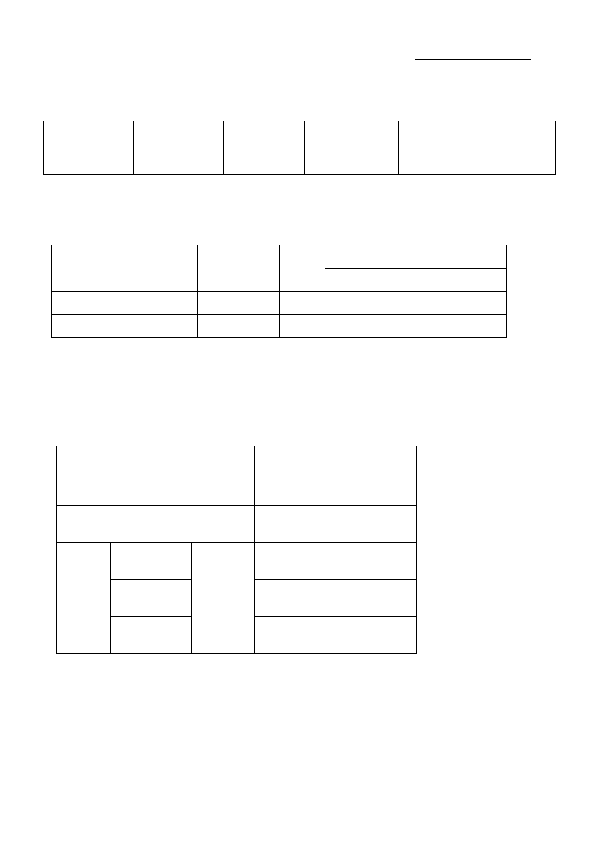
(2) Replacement parts (Parts to be replaced at regular time intervals)
Exchange time
Name of Parts Parts Number Qty /
unit Operation under normal pressure.
Vane 04100653010 6 5,500
Bearing 0A000333000 2 5,500
* When vanes are replaced, replace bearing at the same time. Use ORION specified bearings
that are lubricated with special grease.
* The exchange time is a recommended value in the rotational speed 940/1140 rpm(50/60Hz)
and vacuum 60kPa driving.
* Use the maintenance kit for replacement parts.
Name of Parts Maintenance kit 110 Assembly
Model KRF110
Parts number 04101348010
Kit / unit 1
Vane 6
Bearing 2
Liner (white) 2
Liner (black) 2
Liner (yellow) 4
Items
Liner (red)
Pcs / kit
6
Name of Parts Parts Number Qty/ unit Inspection period Replacement criterion
Liner * 040028390□0 Tobedecidedby
actualpositioning Replacement of
vane Whendamaged.

Spec.No.KRF110-01E
−3−
3. Specifications
Model KRF110-01
Frequency Hz 50 60
Designed capacity *1L/min 1850 2200
Continuous operative
pressure *2kPa Vacuum and pressure in total: 60 or less
Ultimate vacuum *3kPa 90or more
Necessary power Phase・output・pole Three-phase・3.7 kW・6P
Setting for thermal
protection *4ARated current shown in the name plate of motor
Mass kg 54
Painting color Gray (Except some parts)
Installation site Indoor
Permissible
ambient
temperature 0to40℃
Permissible
ambient humidity 65±20%(JIS Z8703)
Installation condition
(Suction air)
Conditions
Conditions where there is no corrosive and
explosive gas exist.
Clean air without vapor and dew condensation,
and less dirt and dust.
*1 Designed capacity: It is the theoretical value calculated from capacity. Please use the
pressure-flow rate diagram for the actual flow rate. It is a designed capacity at rotational
speed 940/1140 rpm(50/60Hz).
*2 Continuous operative pressure: Operative range of pressure. Install the gauge and controller
to the pump or the piping, and use the Dry Pump at the continuous operative pressure or
less.
*3 Ultimate vacuum: Continuous operation is not possible at maximum ultimate vacuum of the
pump. It is used as model selection calculation.
*4 Use the thermal set value as a target since the apparatus and acceptable motor are different
individually.

Spec.No.KRF110-01E
−4−
4. Precautions
(1) Observe precautions, and operate the product within specifications.
(2) Read the instruction manual prior to installation, operation, maintenance and inspection
of the product. Especially pay attention to safety.
(3) The vanes may get damaged if the residual pressure reverses the rotation when the pump
stops. A check valve must be installed within 50 cm from the inlet port or exhaust port for
protection.
(4) Be sure to install the product horizontally on the flat surface.
(5) Operating the product in an enclosed space may cause malfunction due to heat generated
from the pump. Provide good ventilation around the product, so the ambient temperature
does not exceed the permissible level.
(6) Be sure to clean the filters periodically. Failure to do so may cause clogging and result in
trouble due to overload.
(7) Wiring work has to be performed by qualified personnel according to applicable laws and
in-house regulations.
(8) Be sure to install an overload protection such as a thermal relay in the electric circuit.
(9) Be sure to use the product 1,000m or below above sea level.
(10) Adjust Alignment (less than 0.3 mm) correctly when install the motor onto the Pump.
Under the miss-alignment operation, it may cause abnormal noise with vibration then
damaged.
(11) The permitted rotational speed is 750〜1140 rpm. Please use it in this range.
5. Accessories
There is no accessory.

Spec.No.KRF110-01E
−5−
6. Pressure-Flow rate diagram
KRF110-01
Vacuum Specification
0
500
1000
1500
2000
0102030405060 Vacuum(kPa)
Flowrate(L/min)
Pressure Specification
0
500
1000
1500
2000
0 102030405060
Exhaust(kPa)
Flowrate(L/min)
Conditions: 1 atmospheric pressure
20℃
60Hz
50Hz
60Hz
50Hz
(Note)Incasevacuumis0kPa
(Note)Incaseexhaustpressureis0kPa

−6−
27.5
0
-0.2
8
10
φ32
-0.025
-0.050
56
467
246
7070
250
Rc1
OUTLET Rc1
INLET
13.4
(247)
A
120
4-φ11
216
15051
132
A
7 Outline Dimensions
Detail of shaft shape
Spec.No. KRF110-01E
Table of contents
Popular Water Pump manuals by other brands


Hydromatic
Hydromatic DRY PIT Installation and service manual

CTX
CTX MyPOOL Series Operating instructions and maintenance

KSB
KSB Evamatic-Box N 200 l Installation & operating manual

Enerpac
Enerpac PTA-1404 instruction sheet

IWAKI AMERICA
IWAKI AMERICA EH Series instruction manual

Marco
Marco 164 404 15 Instructions for use


