CTX MyPOOL Series Instructions for use
BOMBA DOSIFICADORA PERISTALTICA CON INSTRUMENTO SERIE MyPOOL
NORMAS DE INSTALACIÓîN, USO Y MANUTENCIÓîN
POMPE DOSEUSE PERISTALTIQUE AVEC CONTROLEUR SERIE myPOOL
NOTICE DÌINSTALLATION, EMPLOI ET ENTRETIEN
PERISTALTIC METERING PUMPS WITH INTEGRATED CONTROLLER MyPOOL
SERIES
OPERATING INSTRUCTIONS AND MAINTENANCE
POMPA PERISTALTICA CON STRUMENTO INTEGRATO SERIE MyPOOL
NORME DI INSTALLAZIONE, USO E MANUTENZIONE

2

3
ESPANOL
1.0
NORMAS
GENERALES
...........................................................................................................................................................................5
1.1
ADVERTENCIAS
..................................................................................................................................................................................5
1.2
TRANSPORTE
Y
MOVILIZACI
ON
....................................................................................................................................................5
1.3 USO PREVISTO DE LA
BOMBA
........................................................................................................................................................5
1.4 RIESGOS.................................................................................................................................................................................................. 5
1.5 DOSIFICACION DE LÍQUIDOS NOCIVOS Y/O
TO
XICOS
...........................................................................................................6
1.6 -
MONTAJE
Y
DESMONTAJE
DE LA
BOMBA
..............................................................................................................................6
1.6.1 -
MONTAJE
.....................................................................................................................................................................................6
1.6.2 -
DESMONT
AJE
............................................................................................................................................................................. 6
2.0 -
BOMBA
PERISTALTICA
SERIE
MyPOOL
........................................................................................................................................6
2.1 - PRINCIPIO DE
FUNCIONAMIENTO
DE LAS BOMBAS
PERISTALTICAS
............................................................................6
2.2 -
CARACTERISTICAS COMUNES
....................................................................................................................................................6
2.3 -
MATERIALES
EN
CONTACTO
CON EL
ADITIVO
....................................................................................................................7
3.0 -
INS
TALACION
........................................................................................................................................................................................7
4.0
MANTENIMIENTO
...................................................................................................................................................................................8
5.0 - MyPOOL pH - RX .................................................................................................................................................................................... 9
5.1 - MANDOS (Fig.
4)
................................................................................................................................................................................ 9
5.2 - CARACTERÍSTICAS DEL MyPOOL..................................................................................................................................................9
5.3 - ALARMAS DE SOBREDOSIS ............................................................................................................................................................ 9
5.4 –STAND-BY.......................................................................................................................................................................................... 10
5.5 –ADESCAMENTO DE LA BOMBA ................................................................................................................................................... 10
5.6 - PROCEDIMIENTOS DE CONFIGURACIÓN................................................................................................................................... 10
5.7 - SELECCIÓN DEL VALOR DE SETPOINT ......................................................................................................................................10
5.8 –CALIBRADO...................................................................................................................................................................................... 11
5.9 –ALARMA DE NIVEL......................................................................................................................................................................... 11
6.0 - CABLEADO Y FUNCIONES DE LOS CONECTORES DE SALIDA................................................................................................ 12
7.0 -
INTERVENCIONES
EN
CASO
DE
AVERÍAS
COMUNES
A
LOS
MYPOOL
...........................................................................12
7.1 - AVERIA
MECANICAS
........................................................................................................................................................................12
7.2 - AVERIAS
ELECTRICAS
...................................................................................................................................................................... 12
ENGLISH
1.0 - HINTS AND WARNINGS........................................................................................................................................................................ 14
1.1 - WARNING:..........................................................................................................................................................................................14
1.2 - SHIPPING AND TRANSPORTING THE PUMP................................................................................................................................ 14
1.3 - PROPER USE OF THE PUMP.............................................................................................................................................................14
1.4 - RISKS....................................................................................................................................................................................................14
1.5 - TOXIC AND/OR DANGEROUS LIQUID DOSAGE .........................................................................................................................15
1.6 - ASSEMBLING AND DISMANTLING THE PUMP.......................................................................................................................... 15
1.6.1 - ASSEMBLY ................................................................................................................................................................................. 15
1.6.2 - DISMANTLEMENT ....................................................................................................................................................................15
2.0 - PERISTALTIC PUMPS MyPOOL SERIES .............................................................................................................................................16
2.1 - OPERATION ........................................................................................................................................................................................ 16
2.2 - COMMON FEATURES........................................................................................................................................................................ 16
2.3 - LIQUID ENDS MATERIALS..............................................................................................................................................................16
3.0 - INSTALLATION ...................................................................................................................................................................................... 16
4.0 - MAINTENANCE...................................................................................................................................................................................... 17
5.0 - MyPOOL pH - RX..................................................................................................................................................................................... 18
5.1 - CONTROLS.......................................................................................................................................................................................... 18
5.2 - CHARACTERISTICS OF MyPOOL.................................................................................................................................................... 18
5.3 - OVERDOSING ALARM......................................................................................................................................................................18
5.4 –STAND-BY..........................................................................................................................................................................................18
5.5 - PRIMING..............................................................................................................................................................................................18
5.6 –SETTING.............................................................................................................................................................................................. 19
5.7 - SELECTING THE SET POINT............................................................................................................................................................ 19
5.8 –CALIBRATION ................................................................................................................................................................................... 20
5.9 –LEVEL ALARM ..................................................................................................................................................................................20
6.0 - SERVICE CONNECTOR WIRING DIAGRAMS AND FUNCTIONS.................................................................................................. 21

4
7.0 - TROUBLE-SHOOTING COMMON TO MyPOOL SERIES................................................................................................................... 21
7.1 - MECHANICAL FAULTS ....................................................................................................................................................................21
7.2 - ELECTRICAL FAULTS......................................................................................................................................................................21
FRANÇAIS
1.0 –AVERTISSEMENTS ET CONSEILS ...................................................................................................................................23
1.1 –AVERTISSEMENTS .......................................................................................................................................................................... 23
1.2 –TRANSPORT ET DEPLACEMENT ................................................................................................................................................... 23
1.3 –EMPLOI PREVU DE LA POMPE........................................................................................................................................................ 23
1.4 –RISQUES.............................................................................................................................................................................................23
1.5 –DOSAGE DE LIQUIDES AGRESSIFS ET/OU TOXIQUES ................................................................................................... 24
1.6 –MONTAGE ET DEMONTAGE DE LA POMPE..............................................................................................................................24
1.6.1 - MONTAGE .................................................................................................................................................................................. 24
1.6.2 - DEMONTAGE.............................................................................................................................................................................24
2.3 - MATÉRIAUX EN CONTACT AVEC L'ADDITIF...........................................................................................................................25
3.0 - INSTALLATION......................................................................................................................................................................................25
4.0 -
ENTRETIEN ............................................................................................................................................................................................ 26
5.0 - myPOOL pH - RX .................................................................................................................................................................................. 27
5.1 - COMMANDES (Fig.
7)
..................................................................................................................................................................... 27
5.2 - CARACTÉRISTIQUES DE
myPOOL
............................................................................................................................................... 27
5.3 - ALARME DE SURDOSAGE ............................................................................................................................................................. 27
5.4 –STAND-BY..........................................................................................................................................................................................27
5.5 - AMORÇAGE........................................................................................................................................................................................ 28
5.6 –SETTING.............................................................................................................................................................................................. 28
5.7 - SÉLECTION DU SET POINT..............................................................................................................................................................28
5.8 –CALIBRAGE........................................................................................................................................................................................ 29
5.9 –ALARME DE NIVEAU....................................................................................................................................................................... 29
6.0 - CABLAGES ET FONCTIONS DU CONNECTEUR SERVICES.......................................................................................................... 30
7.0 - INTERVENTIONS EN CAS DE PANNES COMMUNES AUX INSTRUMENTS MYPOOL.............................................................. 30
7.1 –PANNÉS MÉCANIQUES.................................................................................................................................................................... 30
7.2 - DÉFAUTS ÉLECTRIQUES ................................................................................................................................................................. 30
5
(ES) DIRECTIVA "RAEE" 2002/96/CE Y MODIFICACIÓ N SUCESIVA 2003/108/CE SOBRE RESIDUOS DE APARATOS ELÉ
CTRICOS Y ELECTRÓ NICOS
El símbolo que se muestra abajo indica que el producto no puede eliminarse como un residuo urbano normal. Los Aparatos Eléctricos y
Electrónicos (AEE) pueden contener materiales nocivos para el medio ambiente y la salud y por tanto tienen que ser objeto de recogida
selectiva: por consiguiente tienen que eliminarse en vertederos apropiados o entregarse al distribuidor cuando se adquiera uno nuevo, del
mismo tipo o con las mismas funciones. La normativa mencionada arriba, a la que remitimos para más detalles y profundizaciones, prevé
sanciones por la eliminación clandestina de dichos residuos.
1.0
NORMAS
GENERALES
1.1
ADVERTENCIAS
Leer atentamente las advertencias que se citan a continuación, en cuanto proporcionan importantes indicacio- nes referentes a la
seguridad de la instalación, al uso y al mantenimiento.
• Conservar cuidadosamente este manual para poder consultarlo posteriormente.
• Este aparato es conforme a la directiva Nº89/336/CEE "compatibilidad electromagnética" y a la Nº73/23/CEE "directiva de baja
tensión" y su correspondiente modificación Nº93/68/CEE.
NOTA: La bomba está construida según las reglas del arte. Su duración y fiabilidad eléctrica y mecánica serán mayores si se usa
correctamente y si se somete a un mantenimiento regular.
ATENCIÓN: Cualquier intervención o reparación dentro del aparato deberá ser efectuada por personal califi- cado y
autorizado. Se rechaza cualquier responsabilidad por los daños causados por la falta de cumplimien- to de dicha cláusula.
GARANTÍA: 2 años (se excluyen las piezas que normalmente se desgastan, es decir, válvulas, conexiones, virolas para fijar los
tubos, tubitos, filtro válvulas inyectoras), El uso impropio del equipo hace caducar la garantía. La garantía se supone franco
fábrica o donde los distribuidores autorizados.
1.2
TRANSPORTE
Y
MOVILIZACI
ON
El despacho, con cualquier medio de transporte se efectúe incluso puesto en el domicilio del comprador o desti- natario, se entiende que
se efectúa con los riesgos a cargo del comprador. Los reclamos por materiales faltantes deberá efectuarse en el plazo de 10 días a contar
de la fecha de llegada de las mercancías. Mientras que los recla- mos por material defectuoso deberán efectuarse en el plazo de 30 días a
contar de la fecha de recepción. La even- tual devolución de las bombas debe ser previamente concordada con el personal autorizado o
con el distribuidor autorizado.
1.3 USO PREVISTO DE LA
BOMBA
La bomba deberá ser destinada solamente al uso para el cual ha sido específicamente construida, es decir para dosificar líquidos.
Cualquier otro uso debe ser considerado impropio y por lo tanto, peligroso. No se ha previsto el uso de la bomba para aquellas
aplicaciones que no han sido previstas durante la fase de proyectación. Para mayores aclaraciones, el cliente debe ponerse en contacto
con nuestra oficinas, donde recibirá informaciones sobre el tipo de bomba que se encuentra en su poder, y el uso correcto al cual ha
sido destinada.
El constructor no podrá ser considerado responsable por los eventuales, daños que deriven de uso impropio erró- neo o irracional.
1.4
RIESGOS
•
Luego de haber quitado el embalaje controlar que la bomba esté íntegra, en caso de dudas, no utilizar la bomba y consultar al
personal calificado. Los elementos del embalaje, (como por ejemplo sacos de plástico, plástico celular etc.), no deben ser dejados al
alcance de los niños por ser potencialmente peligrosos.
• Antes de conectar la bomba comprobar que los datos de placa correspondan a los de la red de distribución eléctrica. Los datos de
placa se encuentran en la placa adherida a la bomba.
• La realización de la instalación eléctrica debe ser conforme a las normas existentes en el país donde se efec- túa la instalación.
• El uso de un aparato eléctrico cualquiera comporta el cumplimiento de algunas reglas fundamentales, en par- ticular:
- No tocar el aparato ni con los pies ni con las manos húmedas o mojadas

6
- No maniobrar la bomba descalzo (por ejemplo, instalaciones de piscinas).
- No dejar el aparato expuesto a los agentes atmosféricos (lluvia, sol, etc.).
- No permitir que el aparato sea utilizado por niños o por incapaces, sin vigilancia.
• En caso de avería y/o malfuncionamiento de la bomba, apagarla y no manipularla. Para una eventual repa- ración consulte a
nuestros centros de asistencia técnica y solicite el uso de piezas de recambio originales. La falta de cumplimiento a lo anteriormente
indicado, puede comprometer la seguridad de la bomba.
• En el caso que se decida no utilizar más una bomba instalada se recomienda dejarla inoperante desconec- tándola de la red de
alimentación.
Antes de efectuar cualquiera operación de mantenimiento o de limpieza de la bomba dosificadora es necesario:
1. Comprobar que la misma esté desactivada eléctricamente (por ambas polaridades), desconectando los conductores desde los
puntos de contacto de la red a través de la apertura del interruptor omnipolar con una distancia mínima entre los
contactos de 3 mm.
2. Eliminar, de la manera más adecuada (poniendo la máxima atención), la presión que hay en el cuerpo de la bomba y del
tubo de impulsión.
1.5 DOSIFICACION DE LÍQUIDOS NOCIVOS Y/O
T
O
XICOS
Para evitar daños a las personas o cosas que sean causados por líquidos nocivos o por aspiración de vapores tóxicos, además de respetar
las instrucciones que se encuentran en el presente manual, es necesario tener bien presente las siguientes normas:
• Operar según lo que recomiendan los productores del líquido que se va a utilizar.
• Controlar que la parte hidráulica de la bomba no muestre averías o roturas y la bomba se debe utilizar sólo si está en perfectas
condiciones.
• Utilizar tubos adecuados al líquido y a las condiciones de operación de la instalación, introduciéndolos even- tualmente en protecciones
de PVC.
• Antes de desactivar la bomba dosificadora, se debe neutralizar la parte hidráulica con reactivos oportunos.
1.6 -
MONTAJE
Y
DESMONTAJE
DE LA
BOMBA
1.6.1 -
MONTAJE
Todas las bombas dosificadoras que producimos se suministran ya montadas. Para mayor detalle, consulte el anexo, al final del presente
manual donde se encuentran los dibujos del esquema de armado de las bombas y todos los detalles con su nomenclatura
correspondiente, lo cual permite tener un cuadro completo de los com- ponentes de la bomba. Dichos dibujos son, en todo caso
indispensables en el caso se deba proceder al reconoci- miento de piezas con malfuncionamiento o defectuosas.
1.6.2 -
DESMONT
AJE
Para desmontar la bomba, o antes de efectuar una intervención sobre la misma, es necesario:
1. Asegurarse que la misma esté desactivada eléctricamente (por ambas polaridades), desconectando los con- ductores de los puntos de
contacto de la red a través de la apertura del interruptor omnipolar con una distancia mínima entre los contactos de 3 mm .
2. Eliminar de la manera más adecuada (poniendo la máxima atención), la presión existente en el tubo de impulsión.
2.0 -
BOMBA
PERISTALTICA
SERIE
MyPOOL
2.1 - PRINCIPIO DE
FUNCIONAMIENTO
DE LAS BOMBAS
PERISTALTICAS
Por peristálsis se entiende un movimiento propulsor de contracciones automáticas contenido en el interior de un
canal o de un tubo, de éste deriva el término acción peristáltica. Mediante la simulación mecánica de la peristálsis biológica, unos
rodillos comprimen la pared de un tubo formando una retención durante su movimiento, por lo tanto la parte de tubo anteriormente
comprimida vuelve a su forma original produciendo una aspiración de fluido por consecuencia de la depresión que se ha creado. El fluido
seguirá al rodillo hasta que el tubo no vuel- va a ser comprimido. En este momento, un segundo rodillo estará comprimiendo el tubo para
evitar el retorno de flujio, empujando la dosificación inicial de fluido fuera de la bomba y repitiendo la acción de aspiración. Los rodillos
montados sobre rotores especiales permiten un funcionamiento continuo de la bomba gracias a su acción de aspiración por descarga.
2.2 -
CARACTERISTICAS COMUNES
•Equipos fabricados segùn la norma
• Caja de material PP
• Predisposición para sonda de nivel (excluida la sonda de nivel)
• Alimentación eléctrica estándar (se permiten fluctuaciones máximas del ±10%): 230 V a.c. 50/60 Hz monofásica
7
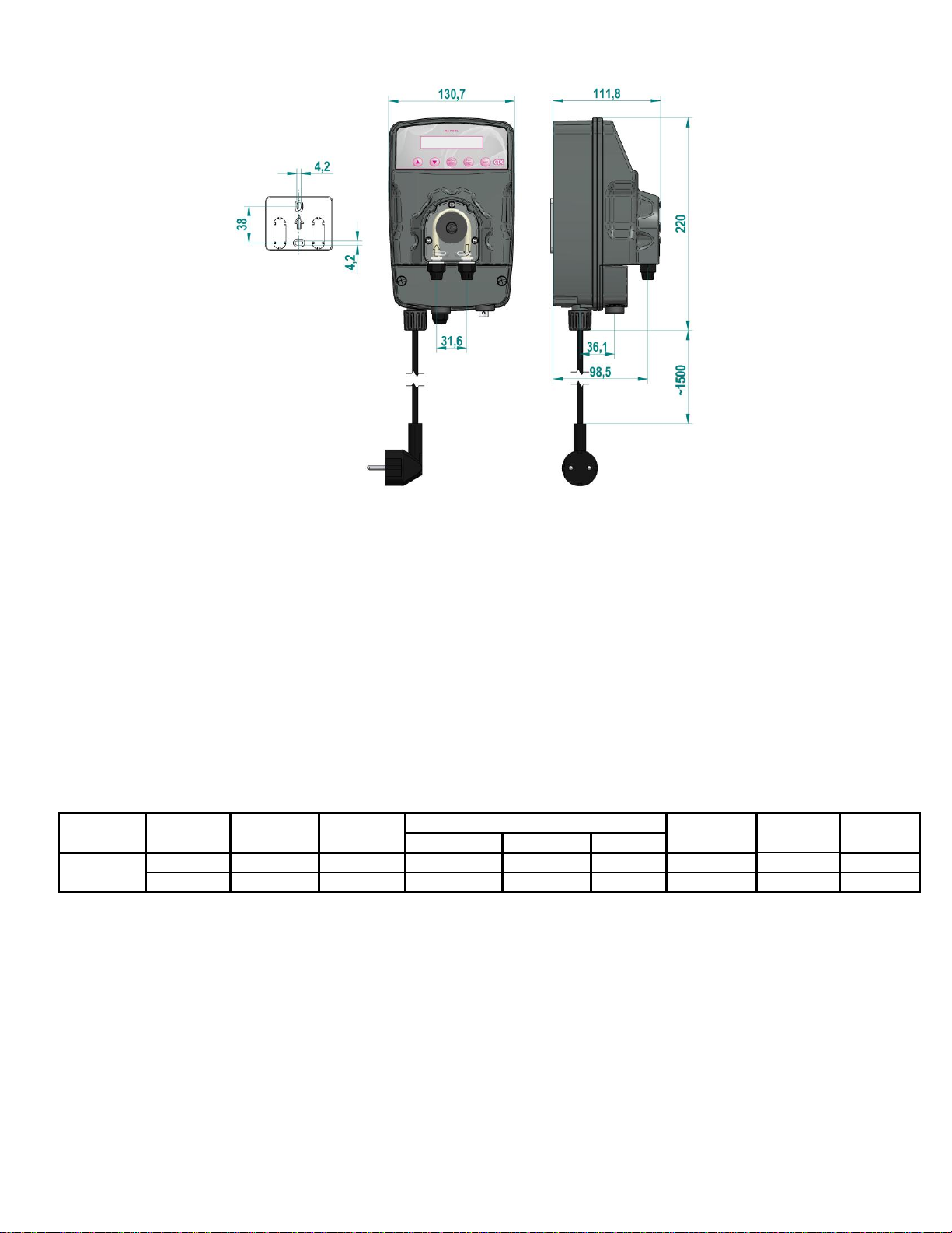
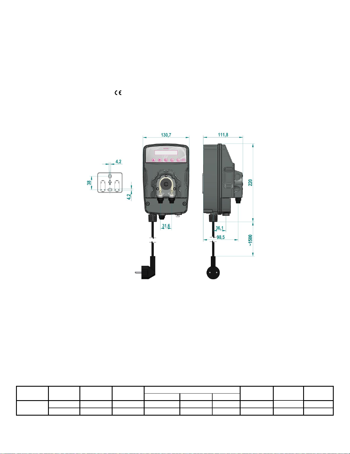
VISTAS Y DIMENSIONES (Fig.
1)
2.3 -
MATERIALES
EN
CONTACTO
CON EL
ADITIVO
1 - Tubo de aplastamiento de la bomba: Santoprene®
2 - Filtro: Standard - Polipropilene
3 - Tubo de aspiracion: PVC Cristal®
4 - Tubo de impulsion: Polietilene
3.0 -
INS
T
ALACION
a. - Instalar la bomba lejos de las fuentes de calor, en un lugar seco a una temperatura ambiental máxima de 40°C mientras que la
temperatura mínima de funcionamiento depende del líquido que se va a dosificar, el cual debe permanecer siempre en estado fluido.
b. - Respetar las normas en vigor en los diferentes países por lo que se refiere a la instalación eléctrica (Fig. 2).
Si el cable de alimentación no está dotado de enchufe eléctrico, el equipo debe quedar conectado con la red de alimentación
utilizando un interruptor onmipolar seccionador que tenga una distancia mínima entre los contactos de 3 mm. antes de
tener acceso a los dispositivos de conexión todos los circuitos deben estar interrumpidos.
CARACTERÍSTICAS TÉCNICAS
Type
MAX
Flow
MAX
Pressure
Net
Weight
MAX Overall Dimensions
Absorbed
Power
Rotation
Speed
Tube
Size
Height
Width
Depth
MyPool
l/h
Bar
Kg
mm
mm
mm
Watts
rpm
mm
1,6
1,5
1,5
220
131
119
10
30
4 x 7
8
230 VAC
BROWN
BLUE
YELLOW / GREEN
N F
12
Fig.
2
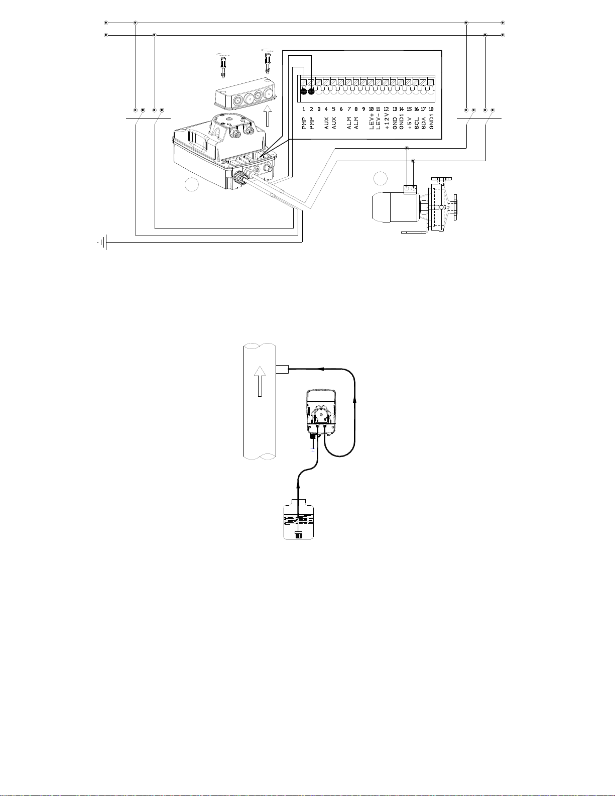
c. - Ubicar la bomba como se indica en la figura 3 teniendo presente que ésta puede quedar fijada, tanto debajo como sobre el nivel del
líquido que se va a dosificar dentro del límite máximo de 2 metros. El punto de inyec- ción debe estar colocado siempre más arriba
del líquido que se va a inyectar.
En el caso de líquidos que emanan vapores agresivos, no instalar la bomba sobre el estanque, a menos que dicho estanque esté
herméticamente cerrado.
Fig.
3
d. - Introducir a fondo los tubos con sus correspondientes empalmes cónicos y bloquearlos con sus virolas para fijarlos.
Antes de fijar el tubo de impulsión a la instalación, cebar la bomba dosificadora. En caso de dificultad en el cebado de la bomba,
aspirar desde el empalme de impul- sión con una jeringa normal y con la bomba funcionando, hasta que se ve subir el líquido en la
jeringa o en el tubo de impulsión. Para la conexión empalme de impulsión-jeringa, usar un trozo de tubo de aspiración.
e. - Evitar curvas inútiles, tanto en el tubo de impulsión, como en el tubo de aspiración.
f. - Aplicar un empalme de acero de 3/8" rosca tipo gas, hembra en el conducto de la instalación que se debe tra- tar, en el punto más
adecuado para efectuar la inyección del producto que se va a dosificar. Dicho empalme no está incluido en el suministro. Atornillar
la válvula de inyección en el empalme, utilizando teflón como guarnición, conectar el tubo al empalme cónico de la válvula de
inyección, y fijarlo con la virola G. La válvula de inyección es a su vez, válvula de retención.
4.0
MANTENIMIENTO
1. Controlar periódicamente el nivel del estanque que contiene la solución que se va a dosificar, para evitar que la bomba funciones en
vacío; si bien en este caso el equipo no sufre ningún daño, es recomendable efectuar este control para evitar daños causador por la
falta de aditivo en la instalación. Las bombas dosificadora de la serie “MYPOOL” están predispuestas para el control del nivel.

9
Aplicando la sonda de nivel que no se encuentra incluida en el suministro, se puede monitorizar el nivel del líquido que se desea
dosificar y que se encuentra en el estanque. Cuando dicho nivel desciende debajo del nivel mínimo establecido, la bomba se detiene
(automáticamente), activando una señal óptica.
2. Controlar por lo menos cada 6 meses, el funcionamiento de la bomba, la hermeticidad de los tornillos y las guarniciones, para
líquidos particularmente agresivos efectuar controles incluso más frecuentes, controlar en particular la concentración del aditivo de la
instalación; una reducción de dicha concentración podría ser cau- sada por el desgaste del tubo de aplastamiento (que en este caso
deben ser substituidas).
3. La firma recomienda limpiar periódicamente la parte hidráulica (válvulas y filtro). No es posible decir cuál es el intervalo de
tiempo en que debe efectuarse dicha limpieza, porque depende del tipo de aplicación. Ni siquiera se puede decir qué tipo de
reactivo se debe utilizar, puesto que depende del aditivo que se usa.
Considerando todo lo anterior, podemos sugerirles cómo intervenir, si la bomba trabaja con hipoclorito de sodio
(el caso más frecuente):
a. Comprobar que ésta esté desactivada eléctricamente (por ambas polaridades), desconectando los conducto- res de los puntos de
contacto de la red a través de un interruptor omnipolar con una distancia mínima entre los contactos de 3 mm.
b. Desconectar el tubo de impulsión de la instalación.
c. Quitar el tubo de aspiración (con filtro) del estanque y sumergirlo en agua limpia.
d. Alimentar la bomba dosificadora y hacerla funcionar con agua durante 5 - 10 minutos.
e. Con la bomba desconectada, sumergir el filtro en una solución de ácido clorhídrico y esperar que el ácido termine su acción de
limpieza.
f. Alimentar nuevamente la bomba, haciéndola funcionar con ácido clorhídrico durante 5 minutos realizando un círculo cerrado con
aspiración e impulsión sumergidos en el mismo estanque.
g. Repetir la operación con agua.
h. Conectar nuevamente la bomba dosificadora a la instalación.
MyPOOL pH -
RX
Fig.
4
5.0 - MyPOOL pH - RX
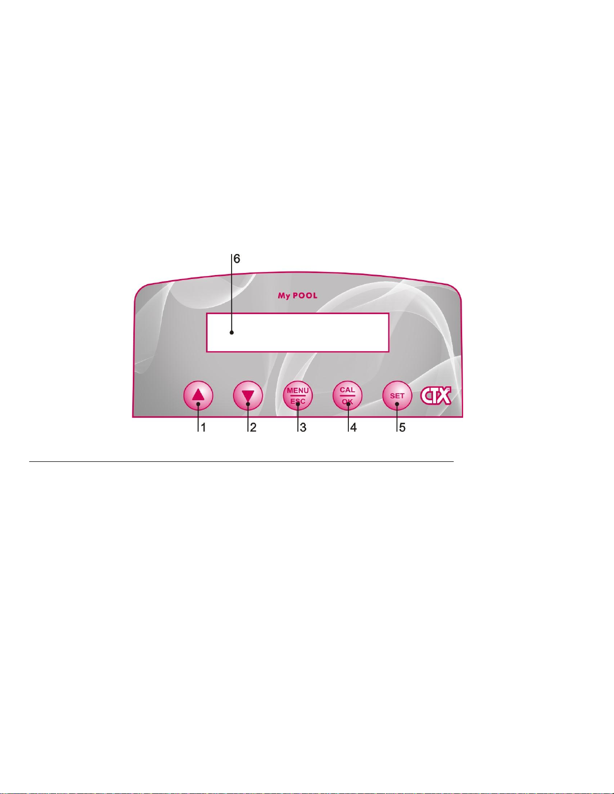
5.1 - MANDOS (Fig.
4)
1 - Tecla incremento valores
2 - Tecla reducción valores
3 - Tecla de menu/salida
4 - Tecla de calibrado del instrumento/confirmacion
5 –Display digital
6 - Tecla SET para programar el setpoint
5.2 - CARACTERÍSTICAS DEL MyPOOL
El MyPOOL es un instrumento de fácil empleo, formado por una bomba peristáltica y una electrónica, capaz de medir y regular los valores
químico-físicos de una piscina, como el pH y el potencial de óxido-reducción (mV). La peristáltica dosifica en modo proporcional de
tiempo pausa.
Programaciones de fábrica MyPOOL: Setpoint= 7,4pH;; intervención: ACID
5.3 - ALARMAS DE SOBREDOSIS
Si el valor de la medida está por debajo de pH 5 o superior de pH 9, la pantalla mostrará un mensaje de error concentración baja o alta del
ácido en la piscina. Para la REDOX el único tipo de dosificación es sólo dirección oxidante, por lo que sólo es posible un error bajo para
valores de mV por debajo de 100.

10
5.4 –STAND-BY
Pulsar en el mismo tiempo la tecla incremento valores y la tecla reducción valores
5.5 –ADESCAMENTO DE LA BOMBA
Con la bomba en STAND-BY pulsar en el mismo tiempo MENU/ESC y CAL/OK.
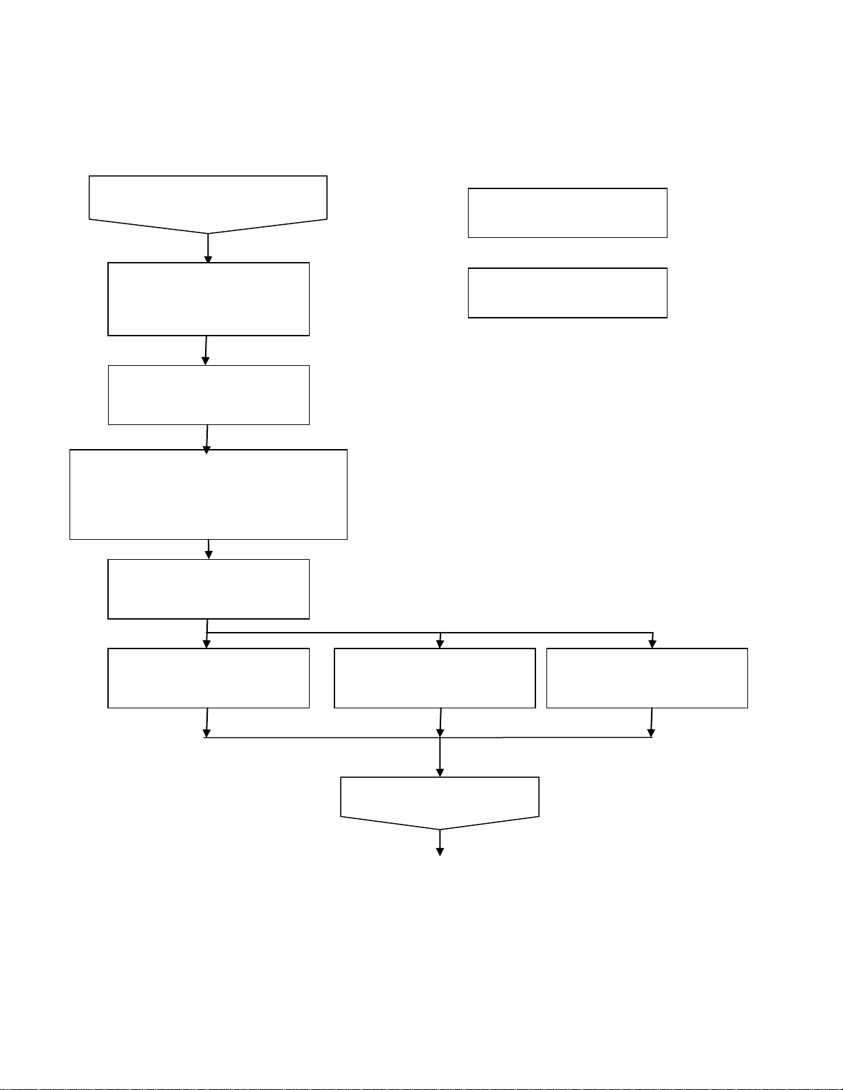
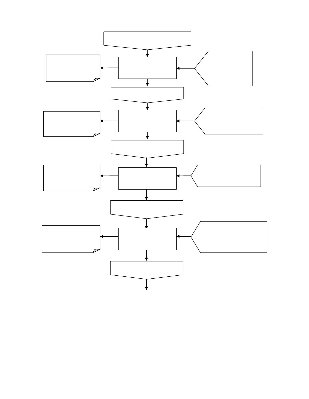
5.6 - PROCEDIMIENTOS DE CONFIGURACIÓN
5.7 - SELECCIÓN DEL VALOR DE SETPOINT
Pulsar la teclar SET por despues 3 segundos hasta no aparece en la pantalla "VALOR CONSINA" Para cambian el valor teclar en el
mismo tiempo la tecla para disminuir o incrementar el valor. Nota que por el pH el valor que se puede programar es desde 6,8 hasta 7,8 y
por el REDOX desde 300 mV hasta 900 mV
Teclar OK para confirmar
IDIOMAS
▼ ESPANOL ▲
Teclar MENU para 5 segundos
TECLAR ESC PARA
SALIR DE EL
MANU
SELEC MEDICION
▼ pH ▲
TECLAR ESC PARA
SALIR DE EL MANU
TECLAR ▲ Y ▼
PARA
SELECIONAR EL
TIPO DE IDIOMA
TECLAR ▲ Y ▼ PARA
SELECIONAR EL TIPO
DE MEDIDA
Teclar OK para confirmar
TIPO DOSIFICACIO
▼ ACIDO (pH-) ▲
TECLAR ESC PARA
SALIR DE EL MANU
TECLAR ▲ Y ▼
PARA SELECIONAR
EL TIPO DE MEDIDA
Teclar OK para confirmar
ETRADA BOMB FIL
▼OFF▲
TECLAR ESC PARA
SALIR DE EL MANU
TECLAR ▲ Y ▼ PARA
SELECIONAR EL LA
ENTRADA DE LA BOMBA
DE FILTRACION.
Teclar OK para confirmar
11
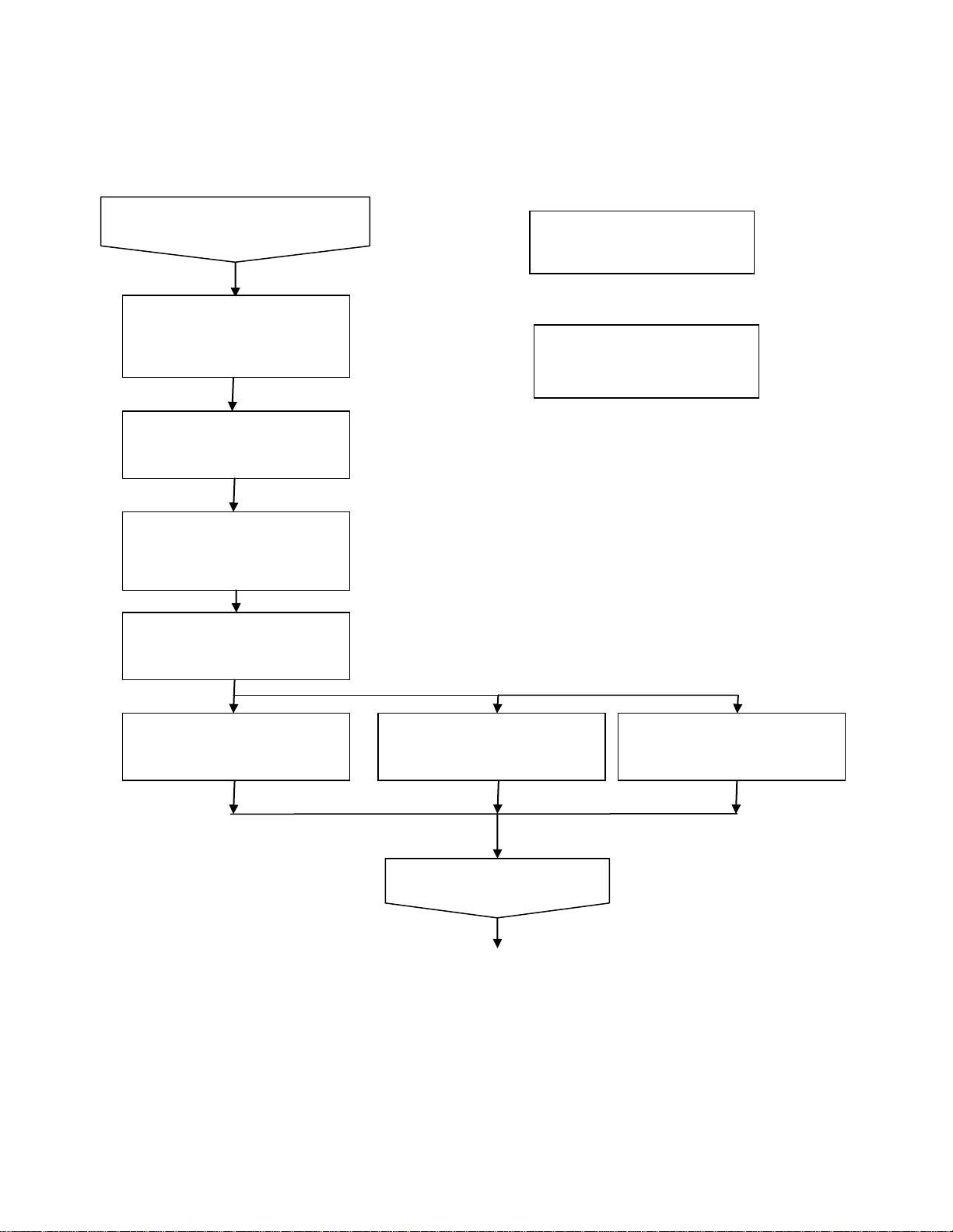
5.8 –CALIBRADO
Pulsar por 5 segundos la tecla CAL/OK. El MENU calibracion aparecerá en la pantalla. Se puede mirar abajo la procedura de calibracion
por el pH, por favor notar que si la calibracion es por el redox estara solo un punto de calibracion con solucion patron 475 mV. Despues la
calibracion en la pantalla estara una persentage de vida de la sonda, abajo 25% esta un error de calibracion y se tiene que reemplazar la
sonda de medidad. La solucion patron estandard es 7 pH y 9 pH, si se utiliza la solucion patron 4 estara uno error de calibracion.
5.9 –ALARMA DE NIVEL
Si la sonda de nivel está conectado a la unidad de control, la bomba se detiene y un mensaje de alarma en la pantalla appire, "NIVEL BAJO
BIDON", si el producto químico está acabado en el tanque
INTRODUZCA SONDA EN
SOLUCION pH7 AGITELA,
DEJELA DENTRO SIN
TOCARLA
Pulse CAL/OK por 5 segundos.
Teclar ESC para salir de el
MENU de calibracion.
CALIBRACION PH 9
9.20PH (90s)
CALIBRACION PH 7
7,20PH (90s)
1. ENJUAGUE LA SONDA 2. INSERTAR
SONDA EN SOLUCIÓN pH4 3. AGITAR
4. INSERTARLA DENTRO SIN TOCAR LA
PUNTA
CALIDAD: 100%
7,07 pH pulse OK
Teclar OK para confirmar
CALIDAD: 50%
7,07 pH pulse OK
ERROR CALIBRACION PH 9
8PH PULSE OK
Pulse OK para confirmar
cada paso
12
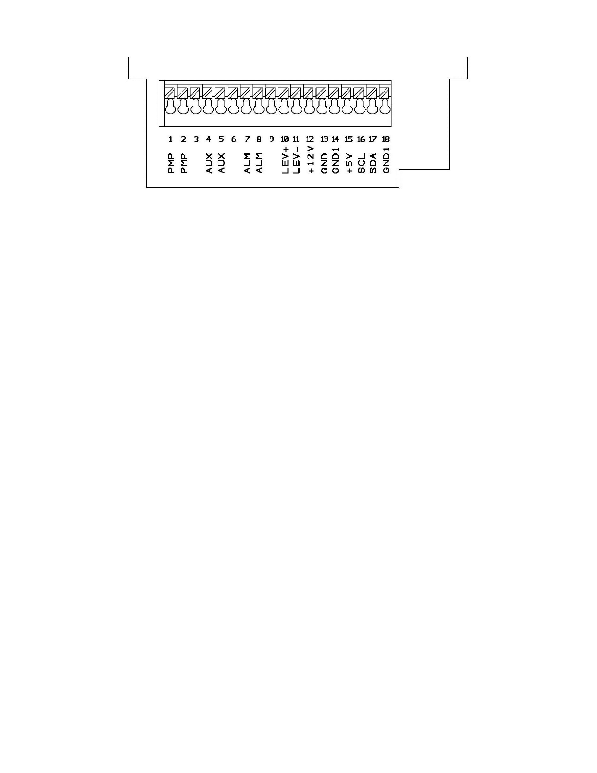
6.0 - CABLEADO Y FUNCIONES DE LOS CONECTORES DE SALIDA
Entrada 1-2 (PMP)= Bomba de ricirculo. Entrada de 230V
Entrada 4-5 (AUX)= Rele con alimentacion de 230V. Esta trabaja en timepo pausa como la bomba dosificadora peristaltica de le equipo.
Entrada 7-8 (ALM)= Rele de alarma. Notar que es un contact libre.
Entrada 10-11 (LEV)= sonda de nivel
Entrada 12-13-14-15-16-17-18= no utilizado
7.0 -
INTERVENCIONES
EN
CASO
DE
AVERÍAS
COMUNES
A
LOS
MYPOOL
7.1 - AVERIA
MECANICAS
Dada la robustez del sistema no se producen verdaderas averías. A veces pueden producirse pérdidas de líquido de algún empalme o
manguito que se hayan aflojado o simplemente por la rotura del tubo de aplastamiento. En este caso los componentes tienen que
sustituirse. una vez solucionada la pérdida hay que limpiar el instrumento de posibles residuos de aditivo que al estancarse podrían
deteriorar químicamente la caja y dañar los circuitos del interior.
❶-, LA PERISTALTICA GIRA PERO NO INTRODUCE ADITIVO
a. Controle la integridad del tubo de bombeo y del tubo de aspiración e impulsión. Si no se observa un hinchamiento o deterioro de los
tubos, compruebe la compatibilidad química del aditivo con el tipo de tubo.
b. Compruebe el estado de obstrucción del filtro
c. Compruebe el estado de las válvulas de aspiración e impulsión, límpielas y vuelva a montarlas en la misma posición.
d. Compruebe el estado de la válvula de inyección
7.2 - AVERIAS
ELECTRICAS
❶, LA PERISTALTICA NO GIRA
a. Controle la regularidad de la alimentación (toma de corriente, enchufe). Si el instrumento sigue inactivo acuda a nuestros centros de
asistencia.
❷EL INSTRUMENTO NO MIDE CORRECTAMENTE
a. Compruebe la calibración del instrumento
b. Compruebe la bondad del electrodo
❸LA PERISTALTICA NO DOSIFICA
a. Compruebe el ajuste del "Setpoint"
b. Controle que el conmutador "ACID/ALK" O "RED/OX." esté en la posición adecuada, es decir, que corresponda a la dosificación
requerida.
❹ANTE LA FALTA DE ADITIVO EL INSTRUMENTO NO PROVOCA UNA ALARMA (para instrumentos dotados de
sonda de nivel) Controle la conexión ente la sonda de nivel y el conector poniendo en cortocircuito los terminales del conector (véase el
Capítulo 8.0 "CLABEADOS Y FUNCIONES DE LOS CONECTORES DE SALIDA"), si la bomba provoca una alarma hay que sustituir
la sonda, si no acuda a nuestros centros de asistencia.
Atención: cuando quite el instrumento de la instalacion actúe con cautela cuando saque el tubo de acople de impulsión de las
peristálticas ya que podría haber una fuga del aditivo que hay quedado en el tubo. También en este caso si la caja entra en
contacto con el aditivo tiene que limpiarse.

13

14
(UK) WASTE OF ELECTRICAL AND ELECTRONIC EQUIPMENT DIRECTIVE (WEEE, RAEE in Italy) 2002/96/EC AND
SUBSEQUENT AMENDMENT 2003/108/EC
The marking shown below indicates that the product cannot be disposed of as part of normal household waste.
Electrical and Electronic Equipment (EEE) can contain materials harmful to health and the environment, and therefore is subject to separate
waste collection: it must be disposed of at appropriate waste collection points or returned to the distributor against purchase of new
equipment of similar type or having the same functions.
The directive mentioned above, to which make reference for further details, provides for punitive actions in case of illegal disposal of such
waste
1.0 - HINTS AND WARNINGS
Please read the warning notices given in this section very carefully, because they provide important information regarding safety in
installation, use and maintenance of the pump.
• Keep this manual in a safe place, so that it will always be available for further consultation.
• The pump complies with EEC directives No.89/336 regarding "electromagnetic compatibility" and No.73/23 regarding "low voltages", as
also the subsequent modification No.93/68.
N.B. The pump has been constructed in accordance with best practice. Both its life and it electrical and mechanical reliability
will be enhanced if it is correctly used and subjected to regular maintenance.
1.1 - WARNING:
Any intervention or repair to the internal parts of the pump must be carried out by qualified and authorized personnel. The
manufacturers decline all responsibility for the consequences of failure to respect this rule.
GUARANTEE: 2 years (the normal wearing parts are excluded, i.e.: valves, nipples, tube nuts, tubing, filter and injection valve).
Improper use of the equipment invalidates the above guarantee. The guarantee is exfac- tory or authorized distributors.
1.2 - SHIPPING AND TRANSPORTING THE PUMP
The pump should always be moved in a vertical (and never in a horizontal) position. No matter what the means of transport employed,
delivery of the pump, even when free to the purchaser's or the addressee's domicile, is always at the purchaser's risk. Claims for any
missing materials must be made within 10 (ten) days of arrival, while claims for defective materials will be considered up to the 30th
(thirtieth) day following receipt. Return of pumps or other materials to us or the authorized distributor must be agreed beforehand with the
responsible personnel.
1.3 - PROPER USE OF THE PUMP
• The pump should be used only for the purpose for which it has been expressly designed, namely the dosing of liquid additives. Any
different use is to be considered improper and therefore dangerous.The pump should not therefore be used for applications that were not
allowed for in its design. In case of doubt, please con- tact our offices for further information about the characteristics of the pump and its
proper use.
The manufactures cannot be held responsible for damage deriving from improper, erroneous or unreasonable use of the pump.
1.4 - RISKS
• After unpacking the pump, make sure it is completely sound. In case of doubt, do not use the pump and con- tact qualified personnel.
The packing materials (especially bags made of plastics, polystyrene, etc.) should be kept out of the reach of children: they constitute
potential sources of danger.
• Before you connect the pump, make sure that the voltage ratings, etc., correspond to your particular power supply. You will find these
values on the rating plate attached to the pump.
• The electrical installation to which the pump is connected must comply with the standards and good prac- tice rule in force in the
country under consideration.
• Use of electrical equipment always implies observance of some basic rules: In particular:
1 -do not touch the equipment with wet or damp hands or feet;
2 -do not operate the pump with bare feet (Example: swimming pool equipment);
3 -do not leave the equipment exposed to the action of the atmospheric agents;
4 -do not allow the pump to be used by children or unskilled individuals without supervision;
• In case of breakdown or improper functioning of the pump, switch off, but do not touch. Contact our techni- cal assistance for any
necessary repairs and insist on the use of original spares. Failure to respect this con- dition could render the pump unsafe for use.
• When you decide to make no further use of an installed pump, make sure to disconnect it from the power supply.
Before carrying out any service on the item, check:
1. Disconnect the pins from the mains or by means of a two poles switch with 3 mm minimum distance between the contacts. (Fig.
4).
2. Relieve all the pressure from the peristaltic pump and injection tube.
3. Drain or flush all dosing liquid from the peristaltic.

15
1.5 - TOXIC AND/OR DANGEROUS LIQUID DOSAGE
To avoid risk from contact with the hazardous liquids or toxic fumes, always adhere to the notes in this instruc- tion manual:
• Follow the instructions of the dosing liquid manufacturer.
• Check the hydraulic part of the pump and use it only if it is in perfect condition.
• Use only the correct materials for the tubing, valves and seals to suit the liquid to be dosed; where possible shield the tubing with PVC
conduit.
• Before disconnecting the metering pump, make sure to flush out and neutralize the pump head with the proper reagent liquid.
1.6 - ASSEMBLING AND DISMANTLING THE PUMP
1.6.1 - ASSEMBLY
All metering pumps are normally supplied fully assembled. For greater clarity, please consult the exploded view of the pump appended at
the end of the manual, which shows all the pump details and a complete overview of all the pump components. These drawings are in any
case quite indispensable whenever defective parts have to be re-ordered. For the same purpose, the appendix also contains other drawings
showing the hydraulic parts (pump head and valves).
1.6.2 - DISMANTLEMENT
Proceed as follows before you dismantle the pump or before performing any other operation on it:
1. Disconnect the pins from the mains or by means of a two poles switch with 3 mm minimum distance between the contacts.
2. Relieve all the pressure from the peristaltic pump and injection tube.
3. Drain or flush all dosing liquid from the peristaltic.
This operation calls for special attention, and you should therefore consult the drawings in Appendix and
Chapter 1.4“RISKS” before you commence work
16
2.0 - PERISTALTIC PUMPS MyPOOL SERIES
2.1 - OPERATION
Peristalsis is a wave of automatic contractions propelling contents along channel or tube, this led to a peristaltic
action. By mechanical simulation of biological peristalsis rollers crush tube walls togheter to form a seal while roller moves along the tube,
then the previously compressed tube regains original form and sucks fluid into the formed vacuum. The fluid will follow the roller until
tube is not compressed any more, then to avoid a flow back a second roller compress the tube, pushing the fluid out of the pump and
repeating the suction action while the pump continues to operate the rollers which are fitted on a special rotor create suction lift and outlet
pressure.
2.2 - COMMON FEATURES
• The products are manufactured according regulation
• Plastic housing in PP
• Level control setting included (supplied without probe)
• Standard power supply (fluctuations not to exceed ±10%):
230 V a.c. 50 Hz single phase. OVERALL DIMENSIONS (Fig. 1)
2.3 - LIQUID ENDS MATERIALS
1 - Hose: Santoprene®
2 - Filter: Standard - Polypropylene
3 - Suction hose: PVC Cristal®
4 - Discharge hose: Polyethylene
3.0 - INSTALLATION
a. - Install the pump in a dry place and well away from sources of heat and, in any case, at environmental tem- peratures not exceeding
40°C. The minimum operating temperature depends on the liquid to be pumped, bearing in mind that it must always remain in a
liquid state.
b. - Carefully observe the regulations in force in the various countries as regards electrical installations (Fig.2). When the supply cable is
devoid of a plug, the equipment should be connected to the supply mains by means of a single-pole circuit breaker having a
minimum distance of 3 mm between the contacts. Before accessing any of the electrical parts, make sure that all the supply
circuits are open.
TECHNICAL CHARATERISTICS
Type
MAX
Flow
MAX
Pressure
Net
Weight
MAX Overall Dimensions
Absorbed
Power
Rotation
Speed
Tube
Size
Height
Width
Depth
MyPool
l/h
Bar
Kg
mm
mm
mm
Watts
rpm
mm
1,6
1,5
1,5
220
131
119
10
30
4 x 7

17
230 VAC
BROWN
BLUE
YELLOW / GREEN
N F
12
c.-Locate the pump as shown in fig. 3 bearing in mind that it may be installed either below or above the level of the liquid to be
dosed, though the level difference should not exceed 2 meters. In case of liquids that generate aggressive vapours, do not install
the pump above the storage tank unless the latter is hermetically sealed.
d.- Slide the hoses over the nipples, pushing them right home and then fix them with appropriate tube nuts (Fig.4).
Before attaching the delivery hose to the plant, prime the peristalòtic by going through the sequence shown in fig. 5. In case of
priming difficulties, use a normal syringe to suck liquid from discharge nipple while the pumèp is in operation, continuing until you
actually see the liquid rise in the syringe. Use a short lenght of suction hose to connect the syringe to the discharge nipple.
f. Try to keep both the suction and discharge hoses as straight as possible, avoiding all unnecessary bends. operation, continuing until
you actually see the liquid rise in the syringe. Use a short length of suction hose to connect the syringe to the discharge nipple. In
case of a pump equipped with an air bleed valve, unscrew the air relief valve B up to all the air in the pump head will be out.
f. -Try to keep both the suction and discharge hose as straight as possible, avoiding all unnecessary bends.
g. - Select the most appropriate injection point on a pipe of the plant to be treated and there fit a 3/8" female steel gas thread connector
(similar to BSPm). This connector is not supplied with the pump. Screw the injection valve to the gas connector, inserting a gasket as
shown in Fig. 6. Then connect the discharge hose to the conical connector on the injection valve and fix it with the supplied tube nut
G. The injection valve also acts as no return valve by means of a cylinder sleeve (elastomer, standard supplied in Viton).
4.0 - MAINTENANCE
1. Check from time to time the chemical solution into the tank to avoid peristaltic pump to dry running. In case this should happen no
damages will occur to the pump. The level control sensor provided as a standard accessory will stop the pump in case of chemical
low level in the tank, anyway a systematic check to avoid lack of chemical in the system is advisable.
2. For finding eventual tears and wear, a three months check to the pump hose is recommended as well as a periodical cleaning for foot
18
filter and injection valve (see point 3). Screws and seals status check is also advisable each
3 months time or at the end of the season. The use of very aggressive or solid suspended chemicals require more frequent controls.
3. As above mentioned, the wetted parts are to be maintained from time to time using the most appropriate cleaning reagent.
Considering the large number of chemicals available in the market a general advice is not possible.
That said, we can suggest in the case the pump works with sodium hypochlorite:
a. Make sure that the pump is deactivated alectrically (both polarities) by detaching the conductors from the contact points of the
mains through an omnipolar switch with a minimum distance between the contacts of 3mm.
b. Disconnect the delivery pipe from the connector
c. Remove the suction pipe (with filter) from the tank and dip it into clean water
d. Start the peristaltic pump and have it work with water for 5-10 minutes
e. With the pump disconnected dip the filter into a solution of 10% hydrochloric acid and wait for the acid to finish its cleaning
action
f. Start again the pump making it work with 10% hydrochloric acid for 5 minutes, creating a closed circuit with suction and
discharge immersed in the same container
g. Repeat the operation with water
h. Connect again the peristaltic pump to the system
MyPOOL pH -
RX
Fig. 4
5.0 - MyPOOL pH - RX
5.1 - CONTROLS
1 - Button to increase the value
2 - Button to decrease the value
3 - Button MENU/ESC
4 - Button to CAL/OK
5 - Button to set the stpoint7 segments display
6 –Digital display
5.2 - CHARACTERISTICS OF MyPOOL
MyPOOL is a friendly user instrument, made by a peristaltic pump and an electronic controller able to measure and settle the chemical-
physical values of a swimming pool, like the pH and the ORP (mV) values. The pump operate in proportional mode.
MyPOOL pH factory defaults : Setpoint= 7,2pH; mode = ON/OFF; intervention: ACID
5.3 - OVERDOSING ALARM
If the value of the measure is below 5 pH or higher of 9 pH, the display will show a message of error low or high concentration of the acid
in the swimming pool. For the REDOX the only type of dosification is only oxidant direction, so it is possible only a low error for values
of mV below 100.
5.4 –STAND-BY
Press in the same time arrow up and arrow down.
5.5 - PRIMING
With the pump in stand-by at the same time press MENU/ESC and CAL/OK.
19
5.6 –SETTING
5.7 - SELECTING THE SET POINT
Press the SET click for after 3 seconds until the screen does not appear in "SET POINT" To change the value in the same time click the
button to decrease or increase the value. Note that the pH-value can be set is from 6.8 to 7.8 and the ORP from 300 mV to 900 mV
Push OK to confirm
LANGUAGE
▼ ENGLISH ▲
Push MENU for 5 seconds
PRESS ESC TO GO
OUT FROM THE
MENU
SELECT MEASURE
▼ pH ▲
PRESS ESC TO GO
OUT FROM THE
MENU
PUSH ▲ AND ▼
TO SELECT THE
LANGUAGE
PUSH ▲ AND ▼ TO
SELECT THE MEASURE
TYPE
Push OK to confirm
DOSING MODE
▼ ACID (pH-) ▲
PRESS ESC TO GO
OUT FROM THE
MENU
PUSH ▲ AND ▼ TO
SELECT THE DIRECTION
OF WORKING
Push OK to confirm
EXTERNAL INPUT
▼OFF▲
PRESS ESC TO GO
OUT FROM THE
MENU
PUSH ▲ AND ▼ TO
ACTIVATE OR
DEACTIVATE THE
RECIRCULATION PUMP
Push OK to confirm
20
5.8 –CALIBRATION
Press for 5 seconds the CAL/OK bottun. The Calibration menu appears on the screen. You can look down the procedure of the calibration
for pH, please note that if calibration is for the redox measure there will be only one point calibration with the buffer solution 475 mV.
After calibration on the display will appear a life persentage of the probe, down 25% there will be a calibration error, this means that the
probe has to be replaced. Standard buffer solution for the pH measure are pH 7 and pH 9, there will be an calibration error if a buffer
solution 4 pH is used.
5.9 –LEVEL ALARM
If the level probe switch is connected to the controller unit, the pump will be stopped and an alarm message will appire on the
display,“TANK LEVEL LOW”, if the chemical is finish in the tank.
INSERT PROBE IN BUFFER
7 pH, MOVE, LET
INSIDEDON'T TOUCH IT
Push CAL/OK for 5 seconds.
Click ESC to exit the
calibration menu.
CALIBRATING PH 9
9.20PH (90s)
CALIBRATING PH 7
7,20PH (90s)
INSERT PROBE IN BUFFER
9 pH, MOVE, LET INSIDE
DON'T TOUCH IT
QUALITY: 100%
7,07 pH PRESS OK
Push OK to confirm
QUALITY: 50%
7,07 pH PRESS OK
CALIBRATION ERR.. PH 9
8 PH PRESS OK
Push OK to confirm
each step
Other manuals for MyPOOL Series
1
Table of contents
Languages:
Other CTX Water Pump manuals


