Aristel AN2209N+ User manual

Aristel Networks –03 8542 2300
1. Product Overview
Thank you for choosing 2.4GHz High Power Wireless Router AN2209N+
1.1.Overview of the Product
AN2209N+ 2.4G High Power Wireless Router is dedicated to long distance wireless network solutions , which
is a revolutionary design with its features of conciseness, quality , and flexibility. It features high output power
and high RX sensitivity which can significantly extend the transmission range and can deliver a more stable
wireless connection and reduce the expense of other equipment.
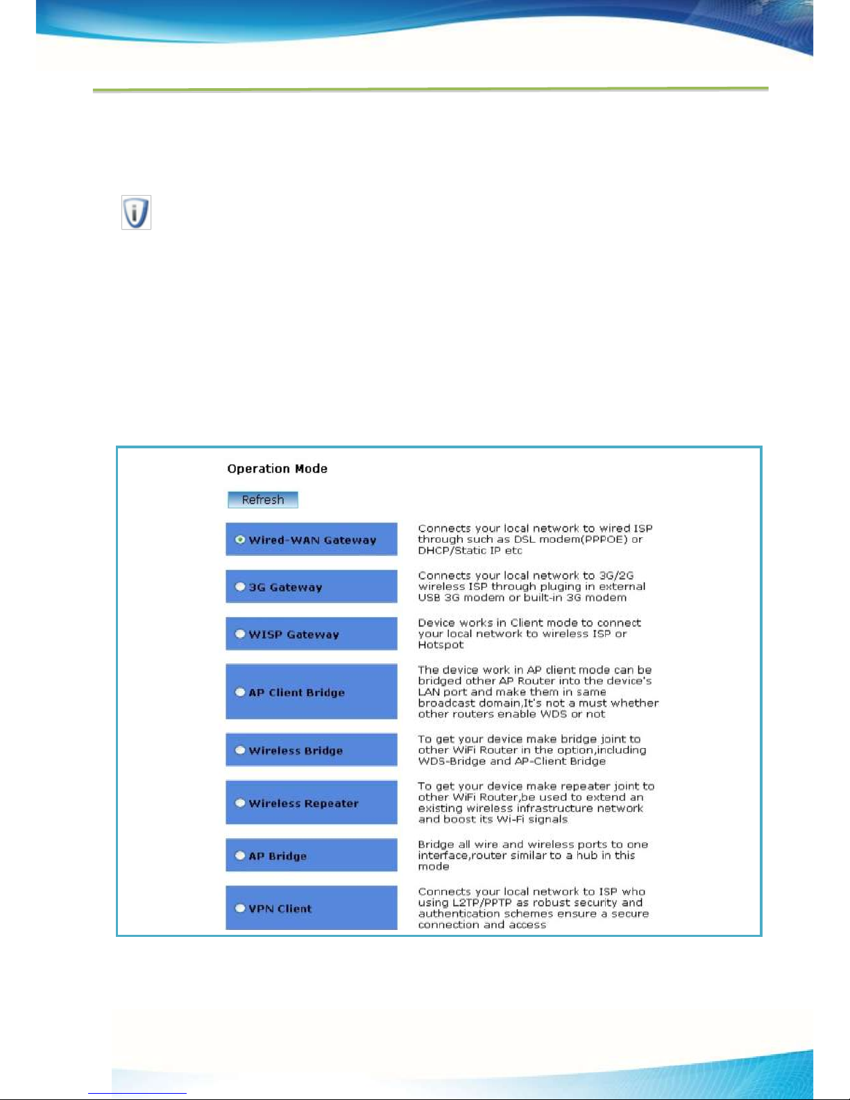
AN2209N+ provides six operation modes for multiple users to access internet:AP/Client Bridge/Client
Router/WDS Bridge/ WDS Repeater/VPN Pass-Through(L2TP、PPTP). Featuring passive power over Ethernet
function is easy to deploy,
To protect wireless connectivity, AN2209N+ encrypt wireless transmissions through 64/128-bit WEP data
encryption and also supports WPA/WPA2.The MAC address filter make you select exactly which stations
should have access to your network. In addition, the User Isolation function can protect the private network
between client and users.
Furthermore, the AN2209N+ supports MSSID up to 4 , which offers easy wireless network isolation for your
data safety and VPN tunnels provide site-to-site security connection; and also supports VLAN, which allows
networks administrator to segregate different services or applications to different designated users, making it
more scalable.
2. Quick Installation Guide
This Chapter will guide you to configure the AP to function in your network and gain access to the internet
through your ISP immediately after successful configuration. More detailed description of the AP’s web-based
utility and functions can be found in “Chapter 4 Configuring the AP”
3.1. Configure the Device
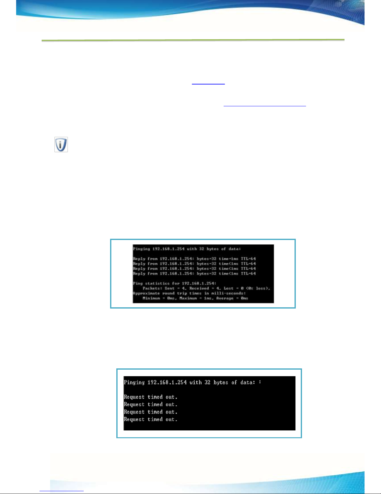
The instructions in this section will help you configure each of your PCs to be able to communicate with the AP.
The default IP address of the AN2209N+ 2.4GHz High Power Wireless router is
192.168.1.11. And the default Subnet Mask is 255.255.255.0. These values can be seen from the LAN. They
can be changed as you desire, as an example we use the default values for description in this guide.
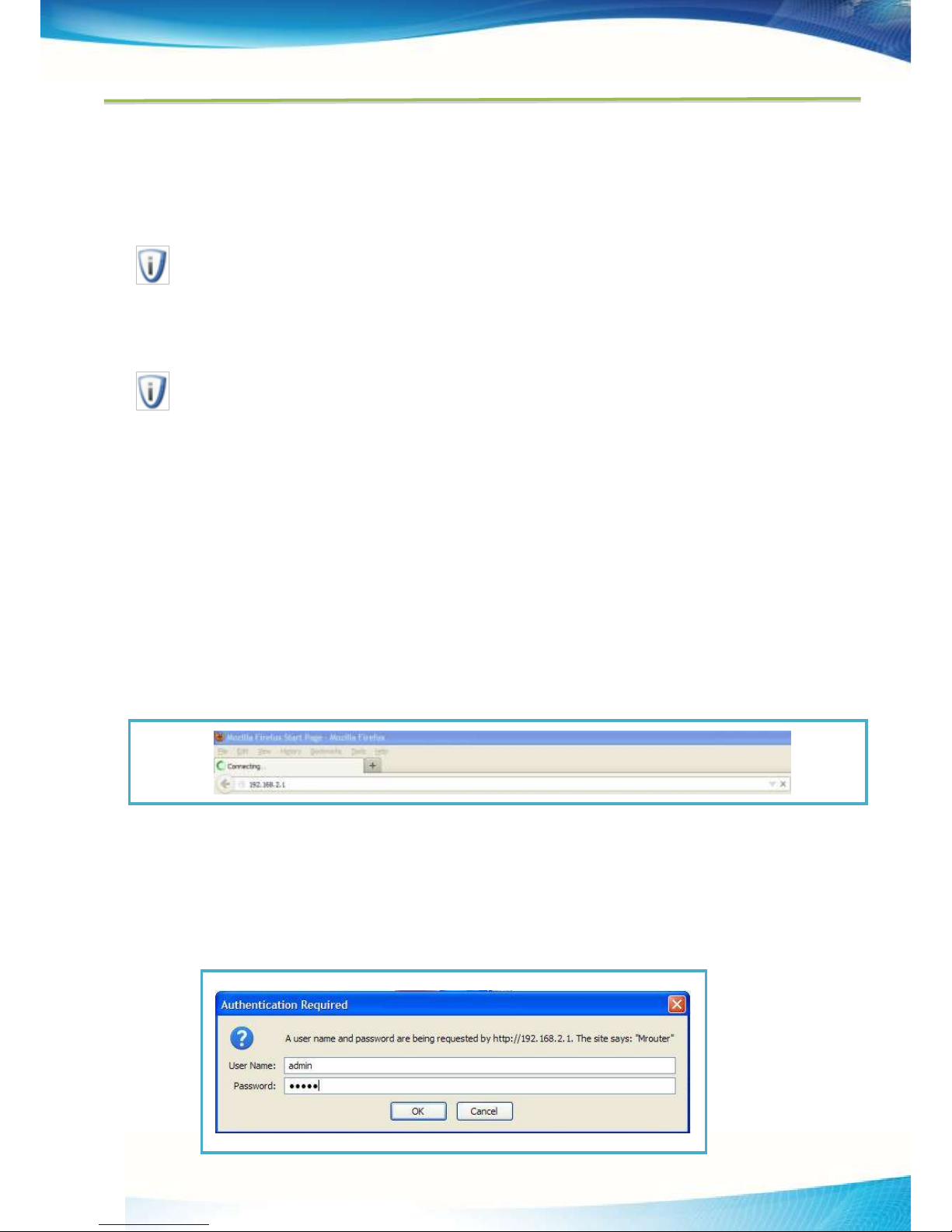
Connect the local PC to the LAN ports of the AP. There are then two ways to configure the IP address for your
PC.
Configure the IP address manually
1. Set up the TCP/IP Protocol for your PC. If you need instructions as to how to do this, please refer
to Appendix B: Configuring the PC

- 2
2. Configure the network parameters. The IP address is 192.168.1.xxx ("xxx" is from 1 to 253),
Subnet Mask is 255.255.255.0, and Gateway is 192.168.1.1 (The AP's default IP address)
Obtain an IP address automatically
This method can be available only when DHCP in section 4.7.1 is enabled.
1. Set up the TCP/IP Protocol in "Obtain an IP address automatically" mode on your PC. If you
need instructions as to how to do this, please refer to Appendix B: Configuring the PC.
2. Power off the AP and PC. Then turn on the AP and restart the PC. The built-in DHCP server will
assign IP address for the PC.
Note:
For Windows 98 OS or earlier, the PC and AP may need to be restarted.
Now, you can run the Ping command in the command prompt to verify the network connection between your
PC and the AP. The following example is in Windows 2000 OS.
Open a command prompt, and type ping 192.168.1.1, and then press Enter.
If the result displayed is similar to that shown in Figure 3-1, the connection between your PC and the AP has
been established.
Figure 3-1 Success result of Ping command
If the result displayed is similar to that shown in Figure 3-2, it means that your PC has not connected to the AP.

- 3
Figure 3-2 Failure result of Ping command
Please check the connection following these steps:
1. Is the connection between your PC and the AP correct?
Note:
The LED of LAN port you link to on the AP and LEDs on your PC's adapter should be lit.
2. Is the TCP/IP configuration for your PC correct?
Note:
If the AP's IP address is 192.168.1.1, your PC's IP address must be within the range of
192.168.1.1 ~ 192.168.1.253, the gateway must be 192.168.1.1.
3.2 Quick Setup
The following instructions will guide you through a few easy steps to configure your AP and connect to Internet.
With a Web-based (Internet Explorer or Netscape®Navigator) utility, it is easy to configure and manage the
AN2209N+ 2.4GHz High Power Wireless Router. The Web-based utility can be used on any Windows,
Macintosh or UNIX OS with a Web browser.
Open your web browser and enter the IP address of the AP (192.168.1.1) and a login screen will display
(shown in Figure 3-3).
Figure 3-3 Login the router
Enter admin for Username and Password (both in lower case letters) on the following login screen. Click OK or
press Enter of your keyboard, and the management page will display.

- 4
Figure 3-4 Login Windows
Note:
If the above screen does not pop-up, it means that your Web-browser has been set to a proxy. Go to Tools
menu>Internet Options>Connections>LAN Settings, in the screen that appears, cancel the Using Proxy
checkbox, and click OK to finish it.
4 Operation Modes
This page will guide you to configure the AP to function in your network and gain access to the internet
through your ISP immediately after successful configuration.More detailed description of the AP’s
web-based utility and functions can be found in “5 . Web Configuration”

- 5
4.1. Wired-WAN Gateway
In this mode, make your device connects to wired ISP through such as DSL modem(PPPOE) or
DHCP/Static IP etc.
After you select “Wired-WAN Gateway” mode just click “Next Step” enter into detailed configuration
page as shown in Figure 4-1.
Figure 4-1 WAN Management
WAN Information: The option displays the current WAN uplink’s status, you can configure the router
to make it connect or disconnect by clicking Connect and Disconnect button manually.
WAN Settings: The option is used to choose the WAN Connection Type(PPPOE/DHCP/Static) for
the internet, The default type is DHCP.If you are given the login parameters(fixed IP Address,
logging ID, etc), pls select Static .If you are given a user name and a password, pls select the type
of your ISP provided(PPPOE).If you are not sure which connection type you use currently pls contact
your ISP to obtain the correct information.
1) If you choose DHCP, the router will automatically get IP parameters from your ISP. You can see
the page as shown in Figure 4-2
Figure4-2 WAN - DHCP
This page displays the WAN IP parameters assigned dynamically by your ISP, including IP address,
Subnet Mask, Default Gateway, DNS etc. User don’t need to input those parameters.
MAC Address Clone –It allows you to clone the MAC address of the managing PC’s adapter to the WAN

- 6
port. This is because some ISPs require that you register the MAC address of your adapter. Usually, you
do not need to change anything here.
Connection Diagnosis –This field displays if you will enable connection Keep-Alive mechanism or not,
which contains ICMP and DNS
ICMP - Use ICMP Echo packets to check if destination could be reached, if destination couldn’t
be reached , will restart connect request again),
DNS - you may choose DNS(To check if the connection works fine by returning DNS packets), pls
enter right DNS address provided by your ISP into the correct fields.
Check Times: The number of checking connection status, available input range of the value is
1~100, default is 5
Check Timeout: The maximum time of trying to connect the destination each time, available
input value range is 1~100, default is 15s
Check Intervals: The waiting time of adjacent checking request, available input range of the
value is 1~100, default is 3s
Check Address: DNS address, its also the destination of ICMP packages goes to
Note:
Once you finished parameter configuration, pls click Apply to save the settings.
Click the Connect button to connect immediately, Click the Disconnect button to disconnect immediately.
2) If you choose Static IP, you should have fixed IP Parameters specified by your ISP. The Static IP
settings page will appear as shown in Figure 4-3.
Figure4-3 WAN - Static IP
You should type the following parameters into the spaces provided:
IP Address - Enter the IP address in dotted-decimal notation provided by your ISP.
Subnet Mask - Enter the subnet Mask in dotted-decimal notation provided by your ISP, usually is

- 7
255.255.255.0.
Default Gateway - (Optional) Enter the gateway IP address in dotted-decimal notation provided by
your ISP.
MTU Size - The normal MTU (Maximum Transmission Unit) value for most Ethernet networks is 1500
Bytes. For some ISPs you may need to modify the MTU. But this is rarely required, and should not
be done unless you are sure it is necessary for your ISP connection.
DNS1 - (Optional) Enter the DNS address in dotted-decimal notation provided by your ISP.
DNS2 - (Optional) Type another DNS address in dotted-decimal notation provided by your ISP if
provided.
For MAC Address Clone and Connection Diagnosis pls refer to “DHCP units”
Note:
Once you finished parameter configuration, pls click Apply to save the settings.
Click the Connect button to connect immediately, Click the Disconnect button to disconnect immediately.
3) If you choose PPPoE, you should enter the following parameters as shown in Figure 4-4.
Figure4-4 WAN - PPPoE
User Name -Enter the User Name and Password provided by your ISP. These fields are
case-sensitive.
Password -Enter the User Name and Password provided by your ISP. These fields are
case-sensitive.
Click the Connect button to connect immediately, Click the Disconnect button to disconnect immediately.

- 8
Click the Advanced checkbox to enable Detail settings, the page shown in Figure 4-5 will then appear.
Figure4-5 PPPoE Advanced - Detail
Packet MTU - The default MTU size is 1480 bytes, which value is usually fine. For some ISPs, you
need modify the MTU. This should not be done unless you are sure it is necessary for your ISP.
Custom DNS –Default is Disable, in this mode will obtain DNS address from ISP automatically . If
you know that your ISP does not automatically transmit DNS addresses to the router during login,
click “Enable” checkbox and enter the IP address in dotted-decimal notation of your ISP’s primary
DNS server. If a secondary DNS server address is available, enter it as well.
LCP Echo Interval - available input range of the value is 1~100, default is 10
LCP Echo Failure Times - available input range of the value is 1~100, default is 12.
ISP Name –To specify your Internet Service Provider name here.
Click the Apply button to save your settings.
Click the Advanced checkbox to enable Custom settings, the page shown in Figure 4-6 will then appear.
Figure4-6 PPPOE Advanced –Custom

- 9
Note:
Custom option only for ISP to debug PPP dialup parameter here, general user pls keep them untouched
4.2. 3G Gateway
In this mode, it connects your local network to 3G/2G wireless ISP through plugging in external USB
3G modem or built-in 3G modem After you select “3G Gateway” mode just click “Next Step” enter into
detailed configuration page as shown in Figure 4-7
Figure4-7 WAN –3G Gateway
UMTS Mode - Most of 3G modem backward compatible with 2G network, basically runs well under
both 3G and 2G mode automatically, you also can force the 3G modem to work in 2G or 3G mode for
those module which the router supported.
APN Mode –Specify Auto and Custom for user.
Auto: Automatic identification mode, in which the device dial up via pre-load APN configuration
from ISP that 3G module scanned, as shown in Figure 4-8

-10
Figure4-8 3G Gateway/APN Mode-Auto
Custom: For custom mode, user could fill in right APN info you have manually, as shown in
Figure 4-9
Figure4-9 3G Gateway/APN Mode-Custom
In this mode, user can click “Edit” button to add or modify APN info manually
Operator –It’s mean default APN which has been integrated into the system
Dial Number –Enter the dial number provided by your ISP
APN Name –An APN is similar to a URL on the WWW, it is what the unit makes a GPRS / UMTS call.
The service provider is able to attach anything to an APN to create a data connection, requirements
for APNs varies between different service providers. Most service providers have an internet portal
which they use to connect to a DHCP Server, thus giving you access to the internet i.e. Some 3G
operators use the APN ‘internet’ for their portal. The default value is “internet”.
Username –Enter the user name provided by your ISP
Password –Enter the password provided by your ISP
PIN Code –Enter the PIN Code provided by your ISP, default is blank

-11
Advanced –In the option you can configure related advanced information of dial plan, such as
configure LCP rules/MTU size/DNS of PPP dialup in detail mode, may add related options in custom
mode
Click the Advanced checkbox to enable Detail settings, Detail option shown in Figure 4-10
Figure4-10 3G Gateway/ Advanced - Detail
Packet MTU - The default MTU size is 1480 bytes, which value is usually fine. For some ISPs, you
need modify the MTU. This should not be done unless you are sure it is necessary for your ISP.
Custom DNS –Default is Disable, in this mode will obtain DNS address from ISP automatically . If
you know that your ISP does not automatically transmit DNS addresses to the router during login,
click “Enable” checkbox and enter the IP address in dotted-decimal notation of your ISP’s primary
DNS server. If a secondary DNS server address is available, enter it as well.
LCP Echo Interval - available input range of the value is 1~100, default is 10
LCP Echo Failure Times - available input range of the value is 1~100, default is 12.
ISP Name –To specify your Internet Service Provider name here.
Click the Apply button to save your settings.
Click the Advanced checkbox to enable Custom settings, the page shown in Figure 4-11 will then appear.
Figure4-11 3G Gateway/ Advanced –Custom

-12
Note:
Custom option only for ISP to debug PPP dialup parameter here, general user pls keep them untouched
Connection Diagnosis –This field displays if you will enable connection Keep-Alive mechanism or not,
which contains ICMP and DNS
ICMP - Use ICMP Echo packets to check if destination could be reached , if destination couldn’t be
reached, it will restart connect request again),
DNS - you may choose DNS(To check if the connection works fine by returning DNS packets), pls
enter right DNS address provided by your ISP into the correct fields.
Check Times: The number of checking connection status, available input range of the value is
1~100, default is 5
Check Timeout: The maximum time of trying to connect the destination each time, available
input value range is 1~100, default is 15s
Check Intervals: The waiting time of adjacent checking request, available input range of the
value is 1~100, default is 3s
Check Address: DNS address, it’s also the destination of ICMP packages goes to
Note:
Once you finished parameter configuration, pls click Apply to save the settings.
Click the Connect button to connect immediately, Click the Disconnect button to disconnect immediately. In
Client mode, AP will act as a wireless station to enable wired host(s) to access wireless AP.
4.3. WISP Gateway
In this mode, The LAN port devices share the same IP from WISP through Wireless port. While

-13
connecting to WISP, the Wireless port works as a WAN port at AP Client Router mode. The Ethernet
port acts as a LAN port as shown in Figure 4-12
Figure4-12 WISP Settings
WISP STA Settings
Step 1: Click “’’button to search nearby AP list, search result as shown in Figure 4-13
Figure4-13 Nearby AP/Hotspot list
Step 2: To select which AP/Hotspot you wish to connect, (e.g join MRouter-CF13)
Step 3: Input WPA Key(Automatically match Channel and Security Mode), then click “ ” to
save the settings, The device will connect to MRouter-CF13 automatically, as shown in Figure
4-14

-14
Figure4-14 WISP STA Settings
Note:
You can check out the device work in WISP STA mode already connected with MRoter-CF13, If you wish to
stop current connection you can click “ ” button to disconnect current connection.
SSID: The SSID of the AP your Device is going to connect to as a client. You can also use the
“’’function to select a SSID to join.
BSSID: The BSSID of the AP your Device is going to connect to as a client. You can also use
the “’’function to select a BSSID to join.
Channel: This field determines which operating frequency will be used. It is not necessary to
change the wireless channel unless you notice interference problems with another nearby
access point. If you select auto, then the Device will select the best channel automatically.
Security Mode: There are three wireless security modes supported by the Device: WEP (Wired
Equivalent Privacy), WPA/WPA2 (Wi-Fi Protected Access/ Wi-Fi Protected Access 2), and
WPA-PSK/WPA2-PSK (Pre-Shared Key)
WISP Access Settings
When you choose WISP Access Internet via Hotspot or other AP take the following steps, as
shown in Figure 4-15
Figure4-15 WISP Access Settings / DHCP
1. DHCP: When the Device connects to a DHCP server, or the ISP supplies you with DHCP connection,
please choose this type. The Device will get the IP address automatically from the DHCP server or
the WISP if you choose the Dynamic IP type. Default is DHCP mode
2. PPPoE - If your wireless ISPs support PPPoE, you should choose this type. In this condition, you
should fill in both the User Name and Password that your ISP supplies.
1) If you choose PPPoE , configuration page as Figure 4-16.

-15
Figure4-16 WISP Access Settings / PPPoE
2) Enter the User Name and Password provided by your ISP.
3. Static IP - In this type, you should manually fill in the IP address, Subnet Mask, Default
Gateway, and DNS IP address, which are specified by your ISP.As shown in Figure 4-17
1) If you choose Static IP Mode, Figure 4-17 will appear.
Figure4-17 WISP Access Settings / Static
IP Address- This is WAN IP address as seen by external users on the Internet (including your
ISP). Enter the IP address into the field.
Subnet Mask- It is used for the WAN IP address, which is usually 255.255.255.0.
Default Gateway- Enter the default gateway in the blank if required.
DNS1- Enter the DNS IP address in the blank if required.
DNS2- If your WISP provides another DNS IP address, enter it in this field.
Note:
The IP parameters should have been provided by your WISP.
2) After you have entered the above necessary parameters and then click “ ” to save the
settings, the device will start to dial-up plan
WISP Access Type: There are three Wireless WAN connection types, PPPOE/DHCP/Static.
To select what type you want to use and configure the IP parameters of the WAN on specified
WAN type
Portal Authentication: The device integrated with Portal Protocol, Currently only support portal
access authentication of Chinese Mobile. You can enable or disable it on this option
MAC Address Clone: It allows you to clone the MAC address of the managing PC’s adapter to

-16
the WAN port. This is because some ISPs require that you register the MAC address of your
adapter. Usually , you do not need to change anything here.
You could fill it in dotted-decimal notation manually or click “ ” button to add it
automatically
Connection Diagnosis: Connection Diagnosis –This field displays if you will enable connection
Keep-Alive mechanism or not, which contains ICMP and DNS
ICMP - Use ICMP Echo packets to check if destination could be reached , if destination
couldn’t be reached it will restart connect request again),
DNS - you may choose DNS(To check if the connection works fine by returning DNS packets),
pls enter right DNS address provided by your ISP into the correct fields.
oCheck Times: The number of checking connection status, available input range of the
value is 1~100, default is 5
oCheck Timeout: The maximum time of trying to connect the destination each time,
available input value range is 1~100, default is 15s
oCheck Intervals: The waiting time of adjacent checking request, available input range of
the value is 1~100, default is 3s
oCheck Address: DNS address, it’s also the destination of ICMP packages goes to
WISP Information
This page is used to display the status that the WiFi station(Client) access other AP or Hotspot
which the device connect with or try to connect with, As shown in Figure 4-18
Figure4-18 WISP Gateway/WISP Information
Connected SSID: Displays what AP or hotspot the device connected with
Connected MAC: Displays the MAC address of the AP or Hotspot that the device connected
with
Connected SSID Signal: Displays wireless signal strength of the AP or Hotspot that the device
connected with
Connected SSID Channel: Displays what channel selected of the AP or Hotspot that the
device connected with
Status: Displays its status of the device with AP or Hotspot

-17
Note:
User could launch a new connect request or disconnect current connection manually.
4.4. AP client bridge
The page is used to setup bridge joint with other AP or wireless Equipment , in this mode it does not
matter if the other side supports WDS or not, you can call it a all-purpose bridge mode. The device
associates with nearby AP and checks the network device combination as a standard mobile
unit(MU).The access point then forms a wireless bridge between the wired LAN and clients through
AN2209N+as shown in Figure 4-19
Figure4-19 AP client Bridge
Bridge Configure

-18
SSID: Input its SSID name of the other side here, or click “ ”to check out nearby AP
list and filter out which one you wish to connect with
BSSID: Input its MAC address of the other side’s AP or to filter it out on scan list when you
click “ ” button
Channel: Displays its channel number of the other side’s AP, defauts is Auto, , you also
could enter into it manually here
Disable Local SSID: Select it to hide local SSID
Security Mode: Default is disable..if you enable local SSID of the device…you can select right
encryption for local SSID here
Local Configure:
Local IP address: Display IP address of LAN port, also you could modify the value here
Local Subnet Mask: Enter into right subnet mask manually here, default is “255.255.255.0”
Access Internet Prohibited: Check it to disable Internet access of the device through other
port…then avoid the uplink conflict may caused by two uplink connection
Disable DHCP Server: Check it to disable the device’s DHCP
Network Measurement: Input the IP address of the target host where the Ping Watch Dog Utility is
sending ping packets to. The option is used to check if setup the connection successfully with the
other side’s AP
4.5. Wireless Bridge
The page use to configure the Wireless Bridge mode, the device provides three operational
modes :WDS Bridge/WDS Bridge+/AP Client Bridge, as shown in Figure 4-20

-19
Figure4-20 Wireless Bridge Settings
WDS Bridge: WDS(Wireless Distribution System) bridge allows AP to communicate with one other
wirelessly. This capability is critical in providing a seamless experience for roaming clients and for
managing multiple wireless networks. In this mode , the device’s SSID is invisible
WDS Bridge+: Same function with WDS Bridge, the difference with WDS Bridge is that the device’s
SSID is visible in this mode
Client Bridge: When in AP Client, AN2209N+ will associate with nearby AP and checks the network
device combination as a standard mobile unit(MU).The access point then forms a wireless bridge
between the wired LAN and clients through AN2209N+
1. If you choose WDS Bridge, This mode bridges the AP and another AP also in bridge mode to
connect two wired LANs. Please input the MAC address of the other AP in the field of MAC Address
or Click Scan button to add it via the scanning list in the bottom. You can see the page as shown in
Figure 4-21

-20
Figure4-21 WDS Bridge
Bridge Configure –Mode
a. Lazy: Automatically to bridge the AP with another AP in this mode, as shown in Figure 4-22
Figure4-22 WDS Bridge Mode –Lazy
Table of contents
Other Aristel Network Router manuals
Popular Network Router manuals by other brands

Cisco
Cisco CISCO1750 installation guide

Cisco
Cisco CISCO7201 Installation and configuration guide

TELEFONICA
TELEFONICA RTL8676 user manual

McDATA
McDATA ULTRANETTM EDGE STORAGE ROUTER 3000 user guide

Cisco
Cisco 3600 Series installation guide

Mellanox Technologies
Mellanox Technologies SwitchX MSX1016X-2BFR Hardware user manual

D-Link
D-Link DES-3624 - Switch - Stackable user guide

D-Link
D-Link DGS-1008P Quick installation guide

Atlantis Land
Atlantis Land Edge-Core A07-ES4524C Specification sheet

Cisco
Cisco Catalyst 4000 Preparing to install

Niobrara
Niobrara MEB II Installation and programming manual

Cisco
Cisco Cable Mgmt Bracket Cisco 7513/7576 installation instructions