AristotleAir AA 72 220 User manual

AristotleAir®Owners Manual - 4/2012
231-944-1876 | www.aristotle-air.com
OPERATION & OWNER’S MANUAL
Reduced Energy Costs
Reduced Absenteeism
Reduced Maintenance Costs
4/2012
AristotleAir®is a unit
ventilator system that
utilizes an energy-efficient
heat recovery ventilator,
as well as an ionization
process for killing germs
and eliminating VOCs.

AristotleAir®Owners Manual - 4/2012
OPERATION & OWNER’S MANUAL
Thank you for purchasing the AristotleAir®.
AristotleAir®can be used either as a retrofit, or new construction. It utilizes energy-efficient
heat exchange and ventilation, as well as ionization science for killing germs and eliminating
VOCs; the whole being more than the sum of its parts.
Proper installation, professional operation and consistent maintenance of this appliance
will ensure that it provides the very best performance and a long, economical service life.
This manual contains the information needed to properly install this appliance, and to use
and care for the appliance in a manner which will ensure its optimum performance.
TABLE OF CONTENTS
Section I: Specifications Specs 1-4
Section 2: Drawings Drawings 1-9
Section 3: Product Overview Overview 1-3
Section 4: Installation Process Installation 1-2
Section 5: Maintenance Maintenance 1-3
Section 6: Warranties Warranties 1-2
Section 7: Manufacturing Facility Manufacturing 1
Installation and wiring to be in accordance with CEC, NEC and local electrical codes.
Please read this
manual before
installing the
AristotleAir® unit.
Note: Due to
ongoing research
and product
development,
specifications,
ratings and
dimensions are
subject to change
without notice.
IMPORTANT!
www.aristotle-air.com

AristotleAir®Owners Manual - 4/2012
1. SPECIFICATIONS

AristotleAir®Owners Manual - 4/2012
How to read the Model #:
EXAMPLE:
AA96320LH-PV-EK1-ECON-UV1
AA Stands for Aristotle-Air.
72 / 82 / 96 Stands for the length
of the unit either 72”, 82” or 96.”
220 / 320 Stands for the CFM rate
of the unit.
LH / RH Stands for the orientation
of the water hook-up. Indicates if
the water hooks up on the left or
right side of the unit.
PV Stands for Power Vent unit and
it will only appear on a unit with 320
CFM in the model number.
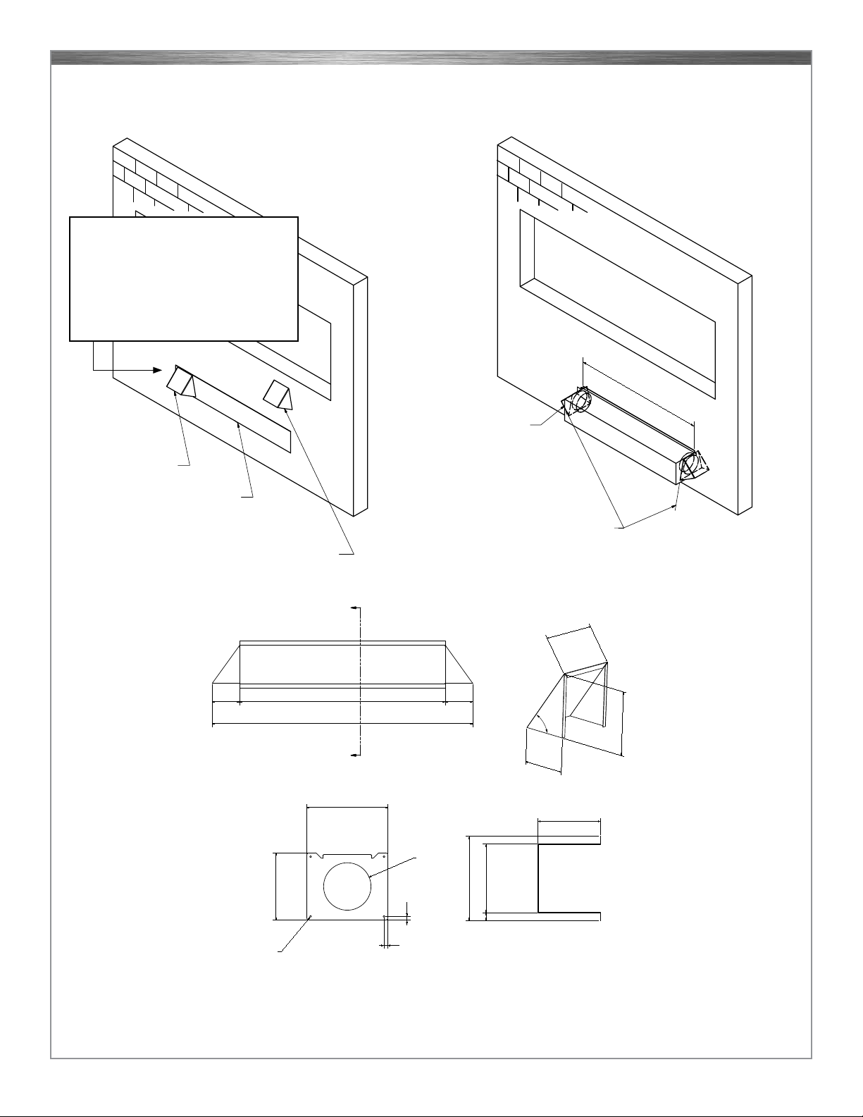
EK- 1,2,3,4 Indicates the exhaust
kit option that was selected for the
unit options 1,2,3 or 4. See drawing
on page “DRAWINGS 6”.
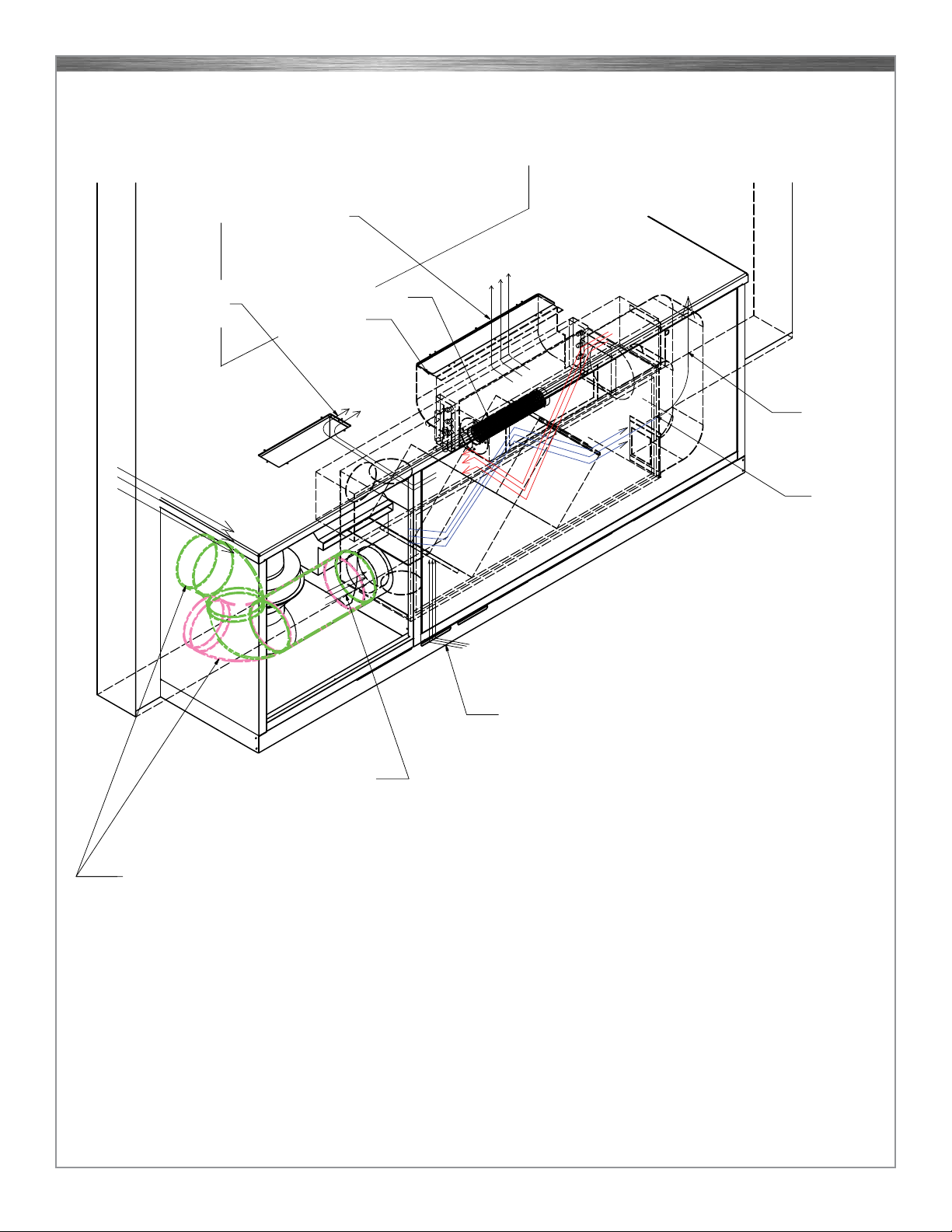
ECON A unit that has an economiz-
er built into it for cooling with fresh,
outside air before it is exposed to
the heat exchange portion of the
unit. All air will still be run through
the PHI cell for purifying the
air. This will only appear in a model
number of a unit with 320 CFM that
has a Power Vent option.
UV1 Stands for the Unit Ventilator
number assigned to the individual
unit per engineered drawing.
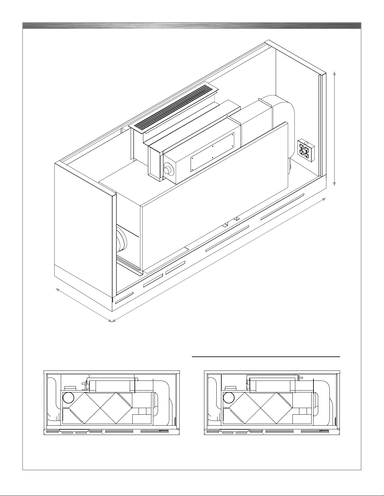
Dimensions: AA 82
19 5/8” D x 82” W x 34” H
Dimensions: AA 96
19 5/8” D x 96” W x 34” H
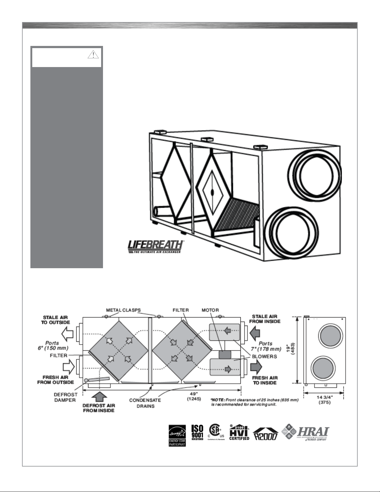
SPECS 1
SECTION 1: SPECIFICATIONS
Dimensions: hot water coil
6” x 24”
Dimensions: AA 72
19 5/8” D x 72” W x 34” H
COMPONETS MODEL
AA 72 220 AA 82 220 AA 82 320 PV AA 96 220 AA 96 320 PV
Output 30,739 BTU 30,739 BTU 30,739 BTU 30,739 BTU 30,739 BTU
Airflow (CFM ) 220 CFM 220 CFM 320 CFM 220 CFM 320 CFM
Total Unit Amps 4.09 amp 4.09 amp 5.23 amp 4.09 amp 5.23 amp
Reheat Coil GPM 3 GPM 3 GPM 3 GPM 3 GPM 3 GPM
Fluid Type (Hot Water) Hot Water @ 160° Hot Water @ 160° Hot Water @ 160° Hot Water @ 160° Hot Water @ 160°
D/B Levels (3 feet away) 63 63 64 63 64
Reheat Coil Inlet Size 3/4” copper 3/4” copper 3/4” copper 3/4” copper 3/4” copper
Filter Size 14” x14” x 1” 14” x14” x 1” 14” x 14” x 1” 14” x 14” x 1” 14” x 14” x 1”
MERV Rating 8 8 8 8 8
Filter Type pleated filter pleated filter pleated filter pleated filter pleated filter
Drain Yes Yes Yes Yes Yes
Distillate Pump Optional Optional Optional Optional Optional
Cabinet Insulation (1”) “Quietflex” R-7 Rating “Quietflex” R-7 Rating “Quietflex” R-7 Rating “Quietflex” R-7 Rating “Quietflex” R-7 Rating
Duct Insulation (1/2”) “Armaflex” R-7 Rating “Armaflex” R-7 Rating “Armaflex” R-7 Rating “Armaflex” R-7 Rating “Armaflex” R-7 Rating
Controls Compatible w/ DDC Compatible w/ DDC Compatible w/ DDC Compatible w/ DDC Compatible w/ DDC
Anti Bacterial Light 1.1 amp 1.1 amp 1.1 amp 1.1 amp
Remote Monitoring Internet Capable Internet Capable Internet Capable Internet Capable Internet Capable
Security Integrated locks Integrated locks Integrated locks Integrated locks Integrated locks
Unit Weight lb. 275 lb. 294 lb. 303 lb. 315 lb. 322 lb.
Construction 18ga s/s & 20ga galv 18gu s/s & 20ga galv 18ga s/s & 20gu galv 18ga s/s & 20gu galv 18ga s/s & 20 galv
MOTOR DATA LIFE BREATH UNIT POWER VENT
Horse Power 1/4 HP PSC 1 speed EBM-PAPST
RPM 1620 RPM Max 2550 RPM Max
Type Thermally Protected Thermally Protected
Supply Voltage 115 v/60 Hz / ph 1 115 v/60 Hz / ph 1 115 v/60 Hz / ph 1 115 v/60 Hz / ph 1
Motor Type HRV 5 speed PSC 5 speed PSC 5 speed PSC 5 speed PSC
Motor HP 1/2 HP 1/2 HP 1/2 HP 1/2 HP
Unit Amps 2.9 amp 2.9 amp 2.9 amp 2.9 amp
Power Vent Motor RPM 2500 rpm 2500 rpm
Power Vent Motor Amp 1.14 amp 1.14 amp
Economizer Damper Motor - - - 6 watts
Total Unit Amp 4.09 amp 4.09 amp 5.23 amp 5.5 amp
Exhaust Options EK = (4) EK # 1 EK # 2 EK # 3 for AA 82 only EK # 4
LEGEND
PV
POWER VENT OPTION
LH
LEFT HAND WATER HOOK-UP
RH
RIGHT HAND WATER
HOOK-UP
GR
GRAINED FINISH
EK
EXHAUST KIT OPTIONS
SW
SWIRLED FINISH
ECON
ECONOMIZER

AristotleAir®Owners Manual - 4/2012
HRV UNIT
AristotleAir®units contain an HRV (Heat Recovery Ventilator) with fully featured 5-speed
electronics to provide complete ventilation control. The HRV unit in each AristotleAir®is a
LIFEBREATH Model 300 DCS (Double Core System for Maximum Recovery) and is
manufactured by AIRIA Brands, Inc.
An HRV is designed to provide fresh air into a building while exhausting an equal amount
of stale air. During the winter months, the incoming cold, fresh air is warmed utilizing the
heat recovered from the stale air before it is exhausted to the outdoors. The core in an
HRV transfers heat from one air stream to the other without mixing air.
Before installation,
careful consideration
must be given to how
this system will operate
when connected to
other existing me-
chancial and electrical
systems, i.e., a boiler
system. All standard
installation procedures
for shutting off water
supply, draining pipes,
and tagging out elec-
trical energy sources
should be followed for
installation.
NEVER install a unit in
a situation where its
normal operation, lack
of operation or partial
failure may result in the
backdrafting or improp-
er function of vented
combustion equipment.
CAUTION
300DCS
SPECS 2

AristotleAir®Owners Manual - 4/2012
THERMALLY CONDUCTIVE, PATENTED ALUMINUM CORE
• The cross-ow heat recovery core transfers heat between the two airstreams
• The two cores are arranged for highly efcient counter current airow
MOTORS AND BLOWERS
• Each air stream has one centrifugal blower driven by a common PSC motor
with 5-speed fan operation
FILTERS
• Two washable air lters in exhaust and supply air streams
DEFROST
• Damper defrost system
CASE
• Twenty gauge pre-painted galvanized steel (G60) for superior corrosion resistance
• Insulated to prevent exterior condensation. Drain connections 2 - 1/2” (12 mm) OD
CONTROLS & ELECTRONICS
Electronic features include:
• 5-speed operation on each mode
• Built-in relay for interfacing to boiler
HRV TEST QUALIFIER
TEST QUALIFIER
• Test was performed on both the AA 82 and the AA 96 units with hoods on both the intake
and exhaust ducts
• Test was performed with power vent fan
• Test was performed using listed duct work and hoods
2 - 8” duct vent hoods with 1/2’ wire mesh screen intake & exhaust locations
2 - 8” round 90 elbows
5’ of 8” round duct pipe at intake & exhaust locations
No Power Vent Fan 220 CFM at Disc. Vent
With Power Vent Fan 320 CFM at Disc. Vent
CONDITIONS CFM INTAKE EXHAUST SUPPLY RETURN
Static PSI
No Fan 220 -0.02 0.01 0.08 -0.38
No Duct, OE Filters
With Fan 320 0.56 0.04 0.03 -0.32
2- 8” 90’s and Hood
5’ piping
ENERGY OUTSIDE HRV DISCHARGE ROOM BOILER FLOW
TRANSFER TEMP (oF) TEMP (oF) TEMP (oF) TEMP (oF) TEMP (oF)
With Fan: 39.4 58.1 104.4 71.2 159.0 3 GPM
16.0 59.9 112.6 73.0 158.9 3 GPM
1.9 57.7 105.0 72.5 151.9 3 GPM
(Above readings reflect unit using this coil: 3R15624)
SPECS 3

A
l
l
P
a
r
t
s
E
x
c
e
p
t
L
a
m
p
!
®
ENTER
THE MATRIX
The matrix of titanium dioxide infused activated carbon cells
inside APCO® RT attracts and holds odors, microbes, and VOC
molecules which are then catalyzed by exposure to UV light.
The carbon cells are self-cleaning and the system is virtually
maintenance-free other than lamp replacement.
Fight Germs & Odors Without Ozone
Unlike many air-cleaning devices, APCO® produces no ozone. UV-C light shining
on the APCO® activated carbon matrix causes a photocatalytic reaction which
transforms odor molecules into harmless water vapor and CO2 which are released
into the airstream.
Mold, germs, and viruses are sterilized by UV-C light shining on the carbon matrix
and in the air as they pass by.
APCO® RT
The Fresh-Aire UV APCO® RT (remote tether)
system works with your central air system to
reduce odors, toxic chemical vapors, germs
and mold in your home. APCO® RT uses the
same technology as the standard APCO unit
but is easier to install in tighter spaces.
Coil
With
UV
Coil
Without
UV
UV-C light suppresses
microbial growth on HVAC
coils and surrounding areas
How APCO® Works
APCO® RT removes airborne contaminants as the air is
circulated by the central air system.
Airborne microbes and volatile organic compounds (odor
molecules) are captured by the APCO® activated carbon
matrix and held in place by the microscopic structure.

Manufactured by Triatomic Environmental, Inc.
WWW.FRESHAIREUV.COM
@freshaireuv.com
© 2012 Triatomic Environmental Inc. TUV-APCO-RT-SPEC 03-12
Furnace installation
Maximum Protection
APCO®RT Dual includes a second UV
lamp which is mounted at the cooling coils.
APCO® RT
For Furnaces & Air Handlers
U.S. patent #7,704,463
Made in USA
Specifications
UV Lamp Standard 100% 254 NM
Germicidal UV-C Spectrum
Quartz Hot Filament
PCO Cell Advanced Monolithic Absorptive PCO cell
with proprietary absorption media and
proven TiO2 photo-catalyst,
Pressure Drop <0.01” w.c. @ 400 FPM
Dimensions Carbon Cell: 3.5”W x 1.25”H x 9.25”D
Enclosure: 6”W x 6”H x 2.5”D
Electrical
ER Series
18-32 VAC, 60 Hz, 0.68 Amps, 16 VA
Low-voltage power-supply
Electrical
ST / DT Series
120-277 VAC, 50/60 Hz,
0.51 Amps/120V Thru 0.22 Amps/277V
High-voltage power-supply
Warranty Lifetime on all parts except lamp
Part Numbers
ER
(Low Voltage)
Internal Mount
Power Supply
TUV-APCO-RT-ER
TUV-APCO-RT-ER2
1 year single
2 year single
ST / DT
(High Voltage)
Internal Mount
Power Supply
TUV-APCO-RT-ST
TUV-APCO-RT-DT
TUV-APCO-RT-ST2
TUV-APCO-RT-DT2
1 year single
1 year dual
2 year single
2 year dual

AristotleAir®Owners Manual - 4/2012
2. DRAWINGS/SCHEMATICS

AristotleAir®Owners Manual - 4/2012
Model AA72 220
Weight: 275 lbs
Model AA82 220
Weight: 294 lbs
Model AA82 320 PV
Weight: 294 lbs
Model AA96 220
Weight: 315 lbs
Model AA96 320 PV
Weight: 315 lbs
19 5/8” deep
72”, 82” or 96” long
34” high
DRAWINGS 1
SECTION 2: DRAWINGS
AristotleAir®Model # AA 72/82/96
AA 72-220 LH
SHOWN WITH HIGH VENT
AA 72-220 RH
SHOWN WITH LOW VENT
AristotleAir®Model # AA 72 Build Sheet

AristotleAir®Owners Manual - 4/2012
AristotleAir®Model # AA 82 Build Sheet
DRAWINGS 2
FRESH, CONDITIONED AIR
TO CLASSROOM
ANTI-BACTERIAL LIGHT
30,000 BTU
HOT WATER COIL
FRESH AIR
(FROM OUTSIDE IN OCCUPIED MODE)
AIR SUPPLY
(IN UNOCCUPIED MODE)
HRV
PRE-WARMED
FRESH AIR

AristotleAir®Owners Manual - 4/2012
AristotleAir®
Model # AA 82
Build Sheet
AA 82-220 LH
AA 82-220 RH
AA 82-320 PV LH
AA 82-320 PV RH
DRAWINGS 3
Left-hand feed
Right-hand feed
Left-hand
power vent
Right-hand
power vent

AristotleAir®Owners Manual - 4/2012
FRESH, CONDITIONED
AIR TO CLASSROOM
ANTI-BACTERIAL LIGHT
30,000 BTU
HOT WATER COIL
FRESH AIR
(FROM OUTSIDE IN OCCUPIED MODE)
AIR SUPPLY
(IN UNOCCUPIED MODE)
HRV
PRE-WARMED
FRESH AIR
CUSTOMER/INSTALLER TO DUCT
FRESH AIR THRU WALL & UNIT REAR WALL
(FOR GROUND-LEVEL & UPPER-LEVEL INSTALLATION)
EXHAUST
(VENTED TO
OUTSIDE)
AristotleAir®Model # AA 96 Build Sheet
DRAWINGS 4

AristotleAir®Owners Manual - 4/2012
AristotleAir®
Model # AA 96
Build Sheet
AA 96-220 LH (SHOWN WITH HIGH VENT)
AA 96-220 RH (SHOWN WITH LOW VENT)
AA 96-320 LH (SHOWN WITH HIGH VENT)
AA 96-320 RH (SHOW WITH LOW VENT)
AA 96-320 PV LH (SHOWN WITH HIGH VENT)
AA 96-320 PV RH (SHOWN WITH LOW VENT)
DRAWINGS 5
Left-hand
feed
Right-hand
feed
Left-hand
power vent
(w/economizer)
Right-hand
power vent
(w/economizer)
Left-hand
feed (w/fan)
Right-hand
feed (w/fan)

AristotleAir®Owners Manual - 4/2012 DRAWINGS 6
AristotleAir®Model # AA 96-800 H/AC Build Sheet
S ECTION A-A
S CALE 1 / 4
S ECTION B- B
S CALE 1 / 4
A
A
B
B
Anti-Bacterial Light Main Supply Fan
Heat & AC Coils
HRV Fan
Assembly
Fresh, Conditioned Air
Fresh Air
(from outside in
Occupied Mode)
Control Box
Filter Box
Main Blower
Power Vent Fan
Heat & AC Coils
Anti-Bacterial Light
S ECTION A-A
S CALE 1 / 4
S ECTION B- B
S CALE 1 / 4
A
A
B
B
Main Blower Heat & AC
Coils
Fresh Air
Intake
Exhaust
Duct
Conditioned
Air Duct
Shown in
Right-Hand Feed
(Available in
Left-Hand Feed)
Hot Water
Chilled Water

AristotleAir®Owners Manual - 4/2012
AristotleAir®Exhaust Options (Note: All options incorporate stainless steel, including the wire mesh guard.)
VENT HOOD
DUCTED
TO EXHAUST
VENT HOOD
DUCTED TO FRESH
AIR INTAKE ON SITE
EK-82-96-1
EXHAUST KIT
W/UPPER-LEVEL
INSTALL
EK-82-96-2
EXHAUST KIT
W/UPPER-LEVEL
INSTALL
VENT HOOD FOR
EXHAUST INSTALLED
ON COVER PLATE
STAINLESS STEEL COVER
PLATE OVER EXISTING
WALL CUTOUT
OPTION TO
BLOCK-IN OPENING
VENT HOOD DUCTED
TO FRESH AIR
INTAKE ON SITE
62”
EK-82-96-2
EXHAUST KIT
W/GROUND-LEVEL
INSTALL
EK-82-3
EXHAUST KIT
W/GROUND-LEVEL
INSTALL
82” UNIT
ONLY
VENT HOOD DUCTED TO
FRESH AIR INTAKE ABOVE SNOW LINE
STAINLESS STEEL COVER PLATE
OVER EXISTING WALL CUTOUT
VENT HOOD FOR
EXHAUST INSTALLED
ON COVER PLATE
STAINLESS STEEL
PLENUM BOX PLACED
OVER EXISTING
WALL CUTOUT
VENT HOOD ATTACHED
TO BOX SIDES
60”
EXTERIOR
WALL
VENT HOOD BOX
OPTION 3 ONLY HOOD ALL
(4) OPTIONS
BASE PLATE OPTIONS (1, 2 & 4) SECTION VIEW
8” 60”
76”
8”
AE
AE
10 1/4”
8”
13 1/4”
7 3/4”
11 1/4”
10 1/4”
11 1/4”
1 1/4”
13 1/4”
11”
5/8” TYP.
5/8” TYP.
5/16” (4) PLCS.
55O
DRAWINGS 7

AristotleAir®Owners Manual - 4/2012
AristotleAir®Exhaust Options (Note: All options incorporate a stainless steel wire mesh guard.)
VENT HOOD
DUCTED
TO EXHAUST
VENT HOOD
DUCTED TO FRESH
AIR INTAKE ON SITE
EK-82-96-1
EXHAUST KIT
W/UPPER-LEVEL
INSTALL
EK-82-96-2
EXHAUST KIT
W/UPPER-LEVEL
INSTALL
VENT HOOD FOR
EXHAUST INSTALLED
ON COVER PLATE
STAINLESS STEEL COVER
PLATE OVER EXISTING
WALL CUTOUT
OPTION TO
BLOCK-IN OPENING
VENT HOOD DUCTED
TO FRESH AIR
INTAKE ON SITE
62”
EK-82-96-2
EXHAUST KIT
W/GROUND-LEVEL
INSTALL
EK-82-3
EXHAUST KIT
W/GROUND-LEVEL
INSTALL
82” UNIT
ONLY
VENT HOOD DUCTED TO
FRESH AIR INTAKE ABOVE SNOW LINE
STAINLESS STEEL COVER PLATE
OVER EXISTING WALL CUTOUT
VENT HOOD FOR
EXHAUST INSTALLED
ON COVER PLATE
STAINLESS STEEL
PLENUM BOX PLACED
OVER EXISTING
WALL CUTOUT
VENT HOOD ATTACHED
TO BOX SIDES
60”
EXTERIOR
WALL
VENT HOOD BOX
OPTION 3 ONLY HOOD ALL
(4) OPTIONS
BASE PLATE OPTIONS (1, 2 & 4) SECTION VIEW
8” 60”
76”
8”
AE
AE
10 1/4”
8”
13 1/4”
7 3/4”
11 1/4”
10 1/4”
11 1/4”
1 1/4”
13 1/4”
11”
5/8” TYP.
5/8” TYP.
5/16” (4) PLCS.
55O
The right end for the exhaust is open
and it would allow the vent to be located
anywhere from 4 1/2” to 24” above the
floor height.
The supply hood Can be located in only
two positions: either at 6” above floor
height or at 24” above floor height.
DRAWINGS 8

AristotleAir®Owners Manual - 4/2012
AristotleAir®Exploded View
DRAWINGS 9
1 TOP
2 RIGHT END WALL PANEL
3 CENTER MULLION
4 LEFT END WALL PANEL
5 REAR BASE RIGHT END
6 REAR BASE LEFT END
7 BOTTOM FRONT DOOR SUPPORT
8 FRONT BASE LOUVERED PLATE
9 FILTER OPENING COVER
10 FRONT DOOR PANEL RIGHT
11 FRONT DOOR PANEL LEFT
12 VENT HOOD BASE PLATE
13 VENT HOOD
14 GALV. FLOOR
15 LIFEBREATH SUPPORT CHANNEL
16 LEFT FILTER SLIDE
17 POWER VENT FAN AND FRESH AIR
DUCT SUPPORT
18 SHORT TOP SUPPORT ANGLE (2)
19 LONG TOP SUPPORT ANGLE (1)
20 INNER BACK WALL PANEL
21 REAR WALL PANEL RIGHT END
22 REAR WALL PANEL LEFT END
23 RIGHT FILTER SLIDE
24 SUPPLY REGISTER GRILL
25 ECONOMIZER REGISTER GRILL
26 REGISTER SUPPLY DUCT
27 ANTIBACTERIAL LIGHT DUCT
28 ROOM SUPPLY DUCT
29 C- SHAPED ROOM SUPPLY DUCT
30 7” ROUND DUCT FOR STALE AIR DUCT
SECTION
31 7” ROUND ELBOW FOR STALE AIR
DUCT SECTION
32 8” ROUND ELBOWS FOR FRESH AIR
DUCT SECTION (2)
33 8” x 8” x 6” REDUCING TEE FOR FRESH
AIR DUCT SECTION
34 COMPLETE LIFEBREATH UNIT
35 LEFT HEAT RECOVERY CORE FOR
LIFEBREATH
36 RIGHT HEAT RECOVERY CORE FOR
LIFEBREATH
37 BLOWER ASSEMBLY FOR LIFEBREATH
38 E BOX CONTROL FOR LIFEBREATH
39 DAMPER MOTOR ASSEMBLY FOR LIFE-
BREATH (NOT SHOWN)
40 GUARDIAN AIR UV ANTIBACTERIAL LIGHT
41 FANTECH POWER VENT MOTOR
42 8” HONEYWELL DAMPER ASSEMBLY FOR
ECONOMIZER DUCT
43 HOT WATER COIL
44 ECONOMIZER FILTER BOX
45 FRESH AIR INTAKE OPENING
46 LEFT LOUVERED INTAKE FOR ROOM AIR
47 RIGHT LOUVERED INTAKE FOR ROOM AIR
48 LEFT/RIGHT LOUVERED OPENINGS FOR
STALE AIR DUCT
49 FRESH AIR INTAKE OPENING TO
LIFEBREATH
50 OPENING FOR ROOM SUPPLY AIR DUCT IN
LIFEBREATH
51 LOUVERED OPENING FOR RECIRCULATED
AIR (UNOCCUPIED MODE)
52 OPENING IN INNER WALL PANEL FOR
STALE AIR DUCT
53 EXHAUST AIR OPENING FROM LIFEBREATH
TO EXHAUST AIR DUCT (PART NOT SEEN)
54 EXHAUST AIR DUCT OPENING IN REAR
PANEL TO OUTSIDE (LOCATED IN FIELD)
55 QUAD PLEX OUTLET BOX FOR UNIT POWER
56 ROOM AIR FILTER
57 ECONOMIZER AIR FILTER
58 OPENING FOR ROOM AIR IN LIFEBREATH
59 OPENING FOR STALE ROOM AIR IN
ARISTOTLEAIR FLOOR
60 STALE AIR OPENING IN LIFEBREATH
61 EXTERIOR EXHAUST VENT HOOD BOX
62 ROOM AIR FILTER OPENING IN ARISTOTLE-
AIR FLOOR
63 OPENING FOR RE-CIRCULATED AIR IN LIFE
BREATH (UNOCCUPIED MODE)
64 OPENINGS FOR REGISTER GRILLS
65 COMPLETE ARISTOTLEAIR UNIT
ARISTOTLE-AIR EXPLODED VIEW PARTS NUMBERS FOR IDENTIFICATION
24. Supply duct grill:
• 4¾” x 25¾” overall
• Opening size is 2½”x 23½”
25. Economizer grill:
• 5¾” x 15¾” overall
• Opening size is 3½” x 13½”

AristotleAir®Owners Manual - 4/2012
3. PRODUCT OVERVIEW

AristotleAir®Owners Manual - 4/2012
SECTION 3: PRODUCT OVERVIEW
OPERATIONS / HOW IT WORKS
A standard, older-style system has two modes: Occupied and Unoccupied.
While in Occupied Mode, the system’s dampers open, allowing fresh air to enter the room to
keep the CO2 level under specified levels. In order to keep building pressure in balance, there
is a fan (with a 1-speed fan motor) on the roof to pull warm air out of the room. One fan can
control 4-6 rooms.
When in Unoccupied Mode, the dampers close and the air is recycled in the room. This
system also allows 750-1,750 CMF’s into the space. (Note: ASHGE Standards are 10 CFM per
person. 20 people = 200 CFM). These dampers are made of metal and in most cases, when
fully closed, there is approximately 20% air leakage. This damper is the only element between
the water coil and outside air and the reason for coil freeze ups. This damper is located at an
opening at the ground level and can cause snow and ice build-up and leakage into the room.
The coil must be removed to clean, which is another disadvantage.
The AristotleAir®system works in the same manner with these key exceptions:
1) It controls the amount of fresh air brought in (10 CFM per person).
2) Rather than discharging the room air out to the atmosphere – as in the old system – the
air passes through heat recovery coils to retain 88% of the energy. This reduces the
amount of energy required to maintain desired room temperatures.
3) In addition, before filtering into the room, all of the air passes through a bacterial-killing
light system for added health benefits.
4) When rooms are unoccupied, the AristotleAir®system reverts to low fan speed, or can be
cycled off, for additional electrical cost savings.
5) This is a self-balancing system. The amount of outside air brought in is the same
as the amount being discharged, elimininating the need for an exhaust fan.
6) The dampers have a rubber seal and closes against a plastic seal ring. The water coil
is located at the top of the unit and the intake and exhaust can be located 30” above
ground. The path through the heat exchanger and connecting ductwork makes the
chance of freezing to almost non-existent: no snow or ice buildup. The filter location
makes maintenance easy. If the heat exchangers need cleaning, they slide out and
wash easily. There is also access to the coil for easy cleaning.
OVERVIEW 1
This manual suits for next models
4
Table of contents
Popular Ventilation Hood manuals by other brands

Ancona
Ancona WPP430 User manual and installation instructions

Electrolux
Electrolux EFB60680BX user manual

Univa
Univa U600SC instruction manual

KOBE
KOBE CH2230SQ Installation instructions and operation manual

montpellier
montpellier CHT0660 Installation and operating instructions

BOMANN
BOMANN DU 7601 G Instruction manual instruction manual