Arkon MAGX2 User manual


MAGX2 User Guide
1
V2.14 1-2-2017
List of Contents
1. Introduction..................................................................................................................................................................... 4
1.1. Operating Principle 4
1.2. Applications 4
1.3. Safety Instructions 4
1.4. Unpacking the flowmeter 4
2. Installation....................................................................................................................................................................... 5
2.1. Remote or Compact 5
2.2. Sensor installation 5
2.3. Dry liner 6
2.4. Installation of the transmitter 7
2.5. Module installation 8
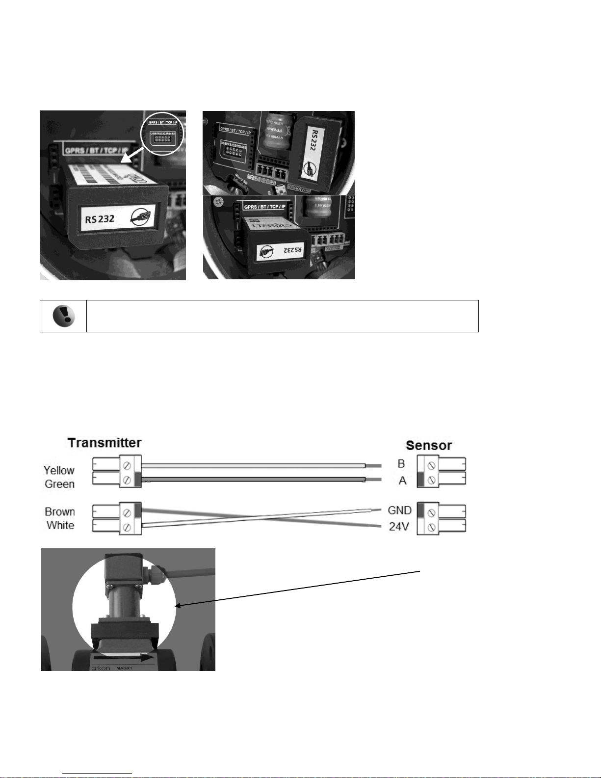
2.6. Cables connections 9
2.7. Potting the remote sensor terminal box for sensor communication module 11
2.8. Fill up of a cable gland of MAGX2 IP68 housing 12
2.9. Ambient conditions 12
3. MAGX2 Transmitter Unit............................................................................................................................................ 13
3.1. Main screen 13
3.2. Flowmeter Menu 16
3.3. Info menu 16
3.4. Display menu 17
3.4.1. Display > Unit Flow..................................................................................................................................... 17
3.4.2. Display > Unit Volume ................................................................................................................................ 17
3.4.3. Display > Unit Temperature......................................................................................................................... 17
3.4.4. Display > Unit Pressure................................................................................................................................ 17
3.4.5. Display > Language...................................................................................................................................... 18
3.4.6. Display > Contrast........................................................................................................................................ 18
3.4.7. Display > Backlight...................................................................................................................................... 18
3.5. User Settings Menu 18
3.5.1. User Settings > Measurement....................................................................................................................... 18
3.5.2. User Settings > Datalogger Interval ............................................................................................................. 19
3.5.3. User Settings > CSV Format........................................................................................................................ 19
3.5.4. User Settings > Air Detector ........................................................................................................................ 19
3.5.5. User Settings > Air Constant........................................................................................................................ 19
3.5.6. User Settings > Delete Auxiliary Volume.................................................................................................... 20
3.5.7. User Settings > Start Delay .......................................................................................................................... 20
3.5.8. User Settings > Samples per Avg................................................................................................................. 20
3.5.9. User Settings > Low Flow Cut-off............................................................................................................... 20
3.5.10.User Settings > Flow Qn .............................................................................................................................. 20
3.5.11.User Settings > Invert Flow.......................................................................................................................... 20
3.5.12.User Settings > Current Loop....................................................................................................................... 21
3.5.13.User Settings > Pulse Output........................................................................................................................ 22
3.5.14.User Settings > Frequency output ................................................................................................................ 25
3.5.15.User Settings > Load Default Settings ......................................................................................................... 26
3.5.16.User Settings > Date Setting......................................................................................................................... 26
3.5.17.User Settings > Time Setting........................................................................................................................ 26
3.5.18.User Settings > Password Setup................................................................................................................... 26
3.5.19.User Settings > Modbus ............................................................................................................................... 26
3.5.20.User Settings > Electrode Cleaning.............................................................................................................. 27
3.5.21.User Settings > Totalizer Cycling ................................................................................................................ 28
3.5.22.User Settings > GSM Settings...................................................................................................................... 28
3.5.23.User Settings > Wi-Fi AP mode................................................................................................................... 29

MAGX2 User Guide
2
V2.14 1-2-2017
3.6. External Measurements Menu 30
3.6.1. External Measurements > Temperature........................................................................................................30
3.6.2. External Measurements > Pressure............................................................................................................... 31
3.7. Service Settings Menu 32
3.7.1. Service Settings > Error Delete .................................................................................................................... 32
3.7.2. Service Settings > OK Delete.......................................................................................................................32
3.7.3. Service Settings > Delete Volume –............................................................................................................. 32
3.7.4. Service Settings > Delete Volume +............................................................................................................. 32
3.7.5. Service Settings > Delete Volume Total ...................................................................................................... 32
3.7.6. Service Settings > Flow Simulation ............................................................................................................. 33
3.7.7. Service Settings > Simulated Flow............................................................................................................... 33
3.7.8. Service Settings > Service mode ..................................................................................................................33
3.8. Factory Settings Menu 33
3.9. Authorize Menu 34
4. Modules.......................................................................................................................................................................... 35
4.1. Power Supply Module 35
4.2. Datalogger 36
4.3. Module positioning 36
4.4. USB Module 37
4.5. RS485 Module 38
4.6. RS232 Module 39
4.7. TCP/IP Module 40
4.8. BLUETOOTH Module 41
4.9. GSM-SMS Module 42
4.10. GPRS Module 43
4.11. Wi-Fi Module 44
4.12. Pulse Output Module 45
4.13. Pulse 230 Module 46
4.14. External Temperature Module 47
4.15. Current Loop Output Module 48
4.16. External Pressure Module 49
5. OIML R49 certification................................................................................................................................................ 50
6. Maintenance.................................................................................................................................................................. 52
6.1. Self –cleaning electrodes 52
7. Liner and electrode selection ....................................................................................................................................... 53
8. Flowmeter Dimensions ................................................................................................................................................. 54
8.1. IP67 Transmitter 54
8.2. IP68 Transmitter 56
9. How to order your MAGX2......................................................................................................................................... 58
10. MAGX2 Error Code Table ........................................................................................................................................ 60
11. Appendix...................................................................................................................................................................... 61
11.1. CE requirements 61
11.2. Warranty 61
11.3. Contact 61

MAGX2 User Guide
3
V2.14 1-2-2017

MAGX2 User Guide
4
V2.14 1-2-2017
1. Introduction
1.1. Operating Principle
The measurement is based on the principle of Faraday‘s law on electromagnetic
induction in which an electric voltage is induced in an electrically conductive body
that moves in a magnetic field.
Liquid flows through a tube in the direction of the magnetic field. Liquid with a
certain minimum electrical conductivity induces a voltage which is detected by
two electrodes located in a 90 degree angle from the magnetic field and the flow
direction.
1.2. Applications
Water / waste
water
Chemical
industry
Food industry
Power
engineering
Agriculture
Effluent
Industry
1.3. Safety Instructions
Please read this manual carefully before using the product.
Keep this manual for future reference. Arkon Flow Systems, s.r.o will not be liable for any
damage caused by improper use of the product or its accessories.
If the device is used any different way than is specified, the electric protection may be disrupted.
The MAGX2 flow converter - flow-meter must not be mounted in explosive hazardous areas.
1.4. Unpacking the flowmeter
While unpacking the flowmeter, conduct a visual check of the
flowmeter upon receipt to make sure the product has not been damaged
during transport.
Check the completeness of the package. In case of any problem,
contact the Arkon sales department without delay.
oFlowmeter
oCables
oCD ROM + Manual
oMounting kit

MAGX2 User Guide
5
V2.14 1-2-2017
2. Installation
2.1. Remote or Compact
Any MAGX2 flowmeter can be delivered in two versions; Compact with
IP67/IP68 or Remote. The compact version has the transmitter unit connected
directly to the sensor body. This version does not require any further mounting
or installation of the transmitter.
The remote version has a separated transmitter. It is connected to the sensor
with a cable. The cable entry into the sensor is protected by a junction box,
which can be potted to IP68 (page 11).
The cable entry on the transmitter side is through a M16x1.5 gland.
The cable type used for the connection between sensor and transmitter for remote versions: UNITRONIC®
LiYCY (TP) 0035 830, 2x2x0.5
The MAGX2 is equipped with an electronic board located inside the sensor neck. This board sends a digital
signal to the transmitter, unlike traditional flowmeters, which send an analogue signal. This allows the MAGX2
to carry its signal over much longer distances than conventional flowmeters; up to 500m is possible.
2.2. Sensor installation
Sensor dimensions can be found on page 54
Proper sensor installation is extremely important in order for your flowmeter to work correctly. Below, you will
find minimum sensor installation requirements that need to be respected at all time. Sensor must not be
installedneck facing down.
Sensor installation
requirements:

MAGX2 User Guide
6
V2.14 1-2-2017
All MAGX2 sensors are supplied with 2 built in earthing electrodes which is sufficient for all applications with
metal pipes and tanks. However on applications where all pipes and tanks are manufactured from plastic, it is
recommended that earthing rings are also installed to ensure the maximum resistance of the sensor to earth
is <1 ohm.
To ensure correct meter operation make sure the earthing rings and sealings around are
centered.
2.3. Dry liner
Flowmeters with a Hard Rubber liner can show incorrect readings during the first 2-3 days after installation.
This is due to the fact that the time needed for transport and the time before installation is long enough for the
liner to dry out, and thus it changes shape/size. This change, in effect, affects reading accuracy. Simply by
keeping the meter wet, this problem solve itself within 2-3 days and no other action is required at all.
Sensor grounding
with earthing rings
Non-conductive (plastic, lined) pipe
Conductive (metal) pipe

MAGX2 User Guide
7
V2.14 1-2-2017
2.4. Installation of the transmitter
In case of a compact flowmeter version, the transmitter will need no further installation, and should be ready
for use. In case of a remote version, the following 4 steps are necessary.
Mount the transmitter to a wall, panel, or DIN-rail.
Wall mounting:
DIN-rail mounting:
Panel mounting:
Connect the transmitter to the signal cable from the sensor.
IP67 Transmitter
To do this, first open the transmitter housing by disconnecting the two parts of the transmitter housing with the
metal “key” that is provided with the meter
IP68 Transmitter
To do this undo four M6x22 screws using allen key nr.5 that is part of the delivery.
The electronics
have to be
protected against
direct sunlight and
high temperatures!
The transmitter
housing should be
exposed to minimal
mechanical strain
only (max. 1kg)!

MAGX2 User Guide
8
V2.14 1-2-2017
After the meter is opened, pull the signal cable through the cable gland on the bottom of the transmitter
housing (see page 5).Connect the connector at the end of the signal cable from the sensor to the transmitter
circuit board.
Electrical installation should only be done by a qualified person. Standard safety regulations
for hazardous electrical installations have to be respected.
The O-ring sealing shall be exchanged every 6 months of operation.
Connect the transmitter to network power.
The customer is assumed to supply its own network power supply cable (90-250VAC, 24VDC or 12VDC,
depending on the type of power supply ordered with the flowmeter). Before connecting to network power, the
cable needs to be properly connected to the transmitter.
First pull the cable end through one of the cable glands (ideally the first on the left looking at the transmitter
housing from the back-side) on the bottom of the transmitter.
Recommend 3x1mm round crosscut cable.
After connecting the power cable, close the housing and connect the cable to network power. This will make
the flowmeter switch on.
For electrical connection the appropriate temperature rated cables have to be used
(Ta=70degC)
Set up the transmitter for use.
You are now ready to start using your flowmeter or to customize its settings as per your requirements. For
example;
- Set-up the measurement unit of flow-rate displayed, e.g. m3/hr.
- Set up of the unit for the volume displayed. For all volume counters this same unit will be used.
2.5. Module installation
- Always check if the module does not have a bent or
broken pin, before placing it in the correct module slot of
the MAGX2 motherboard.
- Always make sure you place the module in the
correct slot of the motherboard! The name that is written
on the module itself has to match the name written next
to the slot. Placing the module in an incorrect slot can
cause damage to the module and the motherboard,
and has to be avoided by careful module installation!
-Check whether you are placing the module in the
correct position. It does matter how you turn the module
to fit the slot! The white line around the actual slot on the
motherboard indicates the correct position of installation.
The bevelled corner should be your point of orientation
(note the picture below).

MAGX2 User Guide
9
V2.14 1-2-2017
- Now you can place the module in its slot:
Correct installation Incorrect installations
Any connection or disconnection of any module has to be done with network power to the
meter switched off.
2.6. Cables connections
The following diagrams show the connections of the cables between sensor and transmitter.
Sensor communication module version 7.1
Use this cable connection only for “sensor to
transmitter communication module - version 7.1”.
The RS232 Module is
placed in a different slot.
The RS232 Module is
placed in the correct
slot, but with the
bevelled corner in the
wrong direction.

MAGX2 User Guide
10
V2.14 1-2-2017
Sensor communication module version 8.0
Use this cable connection only for “sensor to
transmitter communication module –version 8.0”.
“Please note that in different versions of the transmitter, 2 types of connections can be
used. These are 1 x 4-pin connector instead of a 2 x 2-pin connector as shown in the picture.”
Important: In case of IP68 transmitter it is needed to use silicone gel to extra protect cable glands from inside
of the meter. Pour neutral silicone gel into the cable gland from inner side and pull the cable 3mm out of the
housing to make the cable gland extra protected for IP68.

MAGX2 User Guide
11
V2.14 1-2-2017
2.7. Potting the remote sensor terminal box for sensor communication module
For sensor communication module, to guarantee IP68 protection of the sensor, it is necessary to pot the
sensor terminal box properly. The proper way to do this is described below:
Plug the connectors into the sensor (white and green wire adjacent).
Screw the small terminal box to the sensor neck (4 screws).
Fill the terminal box completely with silicone, by squeezing it through the opening on top of the box.
Close the small terminal box with the sealing screw.

MAGX2 User Guide
12
V2.14 1-2-2017
2.8. Fill up of a cable gland of MAGX2 IP68 housing
Fit MAGX2 IP68 housing with standard round cross-cut cable. Example: Power Supply (see pic. 1).
Apply sufficient amount of silicon gel to cable gland of opened round cross cut cable end inside
housing of MAGX2 (see pic. 2).
Slightly pull out the cable while turning the cable to achieve sufficient spread of silicon around the
cable in the cable gland (see pic. 3 and pic. 4).
Do an optical control –focus on full spread of silicone gel around the cable.
Pic. 1 round cross cut cable properly connected inside of MAGX2 IP68 housing
Pic. 2 Application of silicon binder on cable sheat of opened round cross cut cable end
Pic. 3 Manipulation with the cable to achieve sufficient fill up of a cable gland
Pic. 4 Do an optical control to verify sufficient fill up of the cable gland which satisfy IP68 standart
2.9. Ambient conditions
Ambient temperature: -20 –60 ºC
Relative humidity: up to 100%, non-condensing

MAGX2 User Guide
13
V2.14 1-2-2017
3. MAGX2 Transmitter Unit
Module Name:
Module Short Name:
Ordering Code:
MAGX2 Transmitter Unit
Transmitter
MAGX2 T******
MAGX2 IP68 T******
The MAGX2 Transmitter unit is the main part of the flowmeter. It consists of the MAGX2 motherboard, a
graphical display, touch-button controls and a transmitter housing.
Through the display and with help of the touch buttons, you can go through the various menus for data
reading, configuration and setup of your flowmeter.
The following symbols are used in this manual and on the flowmeter display.
ENTER
LEFT
Esc
Selection menu
Back
Key-lock
DOWN
Electrode cleaning
RIGHT
D
Demo mode
UP
SD card present
IP67 version –Touch buttons
Touch-buttons are working on capacitance principle therefore any
conductive material close to button's area will cause button press. Even
water can do it so it is strongly recommended to use key-lock when any
presence of water is expected. 30 seconds after turning the flowmeter
on, touch-buttons autocalibration is started so function of the
touch-buttons may be unstable.
IP68 version –Optometric buttons
Optometric buttons are working on a IR light reflection principle
therefore any strong source of light will cause button press or buttons
inactivity. In dusty areas or where direct sunlight shine directly on a
keypad it is recommended to use key-lock, operate the buttons after
cleaning the glass and shade from sunlight.
The MAGX2 transmitter has a key-lock possibility. You can lock
touch-buttons by touching the Esc key first followed by the Enter key
within one second. This will lock the flowmeter and there will be a lock
symbol on display.
Touching the buttons will have no effect on flowmeters function.
To unlock buttons touch the buttons same way as for locking.
If flowmeter is in cleaning electrode there is a lightning symbol
on display.
Upon starting the flowmeter, you will automatically see the main screen
of the menu.
If transmitter is switched off from power supply longer than 3 months,
output settings may be lost.
3.1. Main screen
Total Volume
This is the total volume counter; the sum of all historical flows for a particular
flowmeter. The user is not able to zero this counter without use of the service
password. Direction of flow is ignored for this counter (negative flow is
calculated the same way as positive flow).

MAGX2 User Guide
14
V2.14 1-2-2017
Positive Volume
This counter is only credited when the measured medium is flowing in the
chosen positive direction. In case the flow is 0, or if it is flowing in the
opposite (negative) direction, the number on the counter remains the same.
Negative Volume
This counter works the same way as the positive volume counter, yet in the
opposite direction. In case the flow is 0, or flowing in the designated positive
direction, the number on this counter will remain the same.
Auxiliary Volume
This is a 2nd total volume counter. It works the same as the Total Volume
positive counter, yet with the only difference being that it can be reset to 0 at
any time, with User Settings password.
Temperature
This item is a temperature indication for the measured medium.
Bar Graph
Represents actual flowrate in a proportion to Qn (100%). The Qn –maximal
flow value can be changed in User Settings.
Time Graph
Shows last 2minutes of actual flow in time based graph (1 second step).
Maximum of the graph is Qn value, can be changed in User Settings.
External Measurements - Temperature
This item is a temperature measured by the connected external temperature
sensor.*
*External Measurement Temperature module must be used.

MAGX2 User Guide
15
V2.14 1-2-2017
External Measurements - Pressure
This item is a pressure measured by the connected pressure sensor.*
*External Measurement Pressure module must be used.
You can cycle through these 9 indication screens by pressing the up and down buttons on the transmitter.
It is possible to change the number
of decimal digits of the actual flow
displayed in the main screen:
decimal numbers
By using the buttons
If value of any Volume counter higher than 4 000 000 m3, then value of Volume show only in
m3 unit. If value of any Volume counter higher than 999 999 999 m3, then this Volume will be
reset to 0.

MAGX2 User Guide
16
V2.14 1-2-2017
3.2. Flowmeter Menu
After pressing the enter button you get to into the root-menu. From
here, you can chose any of the sub-menu’s displayed in the picture on
the right.
Navigate with and select your choice with .
3.3. Info menu
Date
This item shows the current date according to the
transmitter’s setup. It can be changed in the User
Settings menu.
Unit No.
Displays the serial number of the motherboard. This
number is allocated during production by the
manufacturer.
Sensor Unit
No.
Displays the serial number of the sensor. This number
is allocated during production by the manufacturer.
This item is working with sensor ver. 8 and newer.
Error (min)
The number of minutes the device was not measuring
because of errors.
OK (min)
The number of minutes that the device measured
correctly.
Diameter
This item shows the nominal sensor diameter that is
currently configured for the given flowmeter.
Flow Qn
Here, the flowmeter displays the predicted nominal
flow. Values can be changed under User Settings.
Firmware No.
This shows the current firmware version.
Actual Error
This shows all actual errors (see chapter 10).
Power
frequency
Identifies the network power supply frequency.
SD card
present
Shows if the SD card is inserted in the flowmeter.
GSM module
present
Shows if the GPRS module is inserted in the
flowmeter.
GPRS IP
address
Displays IP address of GPRS module.
GSM Signal
Signal strength of the GSM SMS Module.
GPRS module
present
Shows if the GPRS module is inserted in the
flowmeter.
Wifi module
present
Shows if the Wi-Fi module is inserted in the flowmeter.

MAGX2 User Guide
17
V2.14 1-2-2017
3.4. Display menu
3.4.1. Display > Unit Flow
Setup of the displayed measurement unit for current flow.
Back with no change
Item selection
Selection identification
Confirmation of setup and saving to memory
UKG / min
UK gallon per minute
USG / min
US gallon per minute
m3 / h
Cubic meters per hour
l / min
Litres per minute
l / s
Litres per second
3.4.2. Display > Unit Volume
Setup of the displayed measurement unit for total flow.
Back with no change
Item selection
Selection identification
Confirmation of setup and saving to memory
UKG
UK gallon
USG
US gallon
m3
Cubic meter
l
Litre
3.4.3. Display > Unit Temperature
Setup of the displayed measurement unit of temperature indication
and external measurement of temperature.
Back with no change
Item selection
Selection identification
Confirmation of setup and saving to memory
C
Degrees Celsius
F
Degrees Fahrenheit
3.4.4. Display > Unit Pressure
Setup of the displayed measurement unit of the external pressure
measurement.
Back with no change
Item selection
Selection identification
Confirmation of setup and saving to memory
bar
Pressure in bar unit (1 bar = 100 kPa = 14,50 psi)
psi
Pressure in psi unit (1 psi = 6,89 kPa = 0,07 bar)

MAGX2 User Guide
18
V2.14 1-2-2017
3.4.5. Display > Language
Setup of the language for flowmeter menu.
Back with no change
Item selection
Selection identification
Confirmation of setup and saving to memory
ENG
English
SPA
Spanish
RUS
Russian
UKR
Ukrainian
TUR
Turkish
3.4.6. Display > Contrast
Contrast of the display setup.
Possible range: 0 –100 %
Back with no change
Selection of digit position
Value setting
Confirmation of setup and saving to memory
3.4.7. Display > Backlight
Setup of the backlight for flowmeter display.
Back with no change
Item selection
Selection identification
Confirmation of setup and saving to memory
10 seconds
The backlight would turn off 10 seconds after the last
button touch
Always ON
The backlight will be always on
3.5. User Settings Menu
To enter this part of the menu, it is necessary to enter the User Password.
The default factory setting is 1111. See page 26.for user password settings.
3.5.1. User Settings > Measurement
This option allows selecting flow measurement to be on or off.
Back with no change
Item selection
Selection identification
Confirmation of setup and saving to memory
Run
The device is measuring, the totalizers are active
Stop
The display will show a value, yet the totalizers are off

MAGX2 User Guide
19
V2.14 1-2-2017
3.5.2. User Settings > Datalogger Interval
This option allows select how often will be totalizers saved on
SD card.
Back with no change
Item selection
Selection identification
Confirmation of setup and saving to memory
OFF
Totalizer is not used (SD card not necessary)
1 minute
The interval of saving totalizers; SD card needed
5 minutes
10 minutes
15 minutes
30 minutes
1 hour
2 hours
6 hours
12 hours
24 hours
While there is an error “SD card not inserted” or “SD Open file” active and the user plugs in the SD
card, error will disappear after next write to the datalogger. It is recommended to setup the
datalogger interval again or restart the flowmeter after every SD card plug.
It is not recommended to use 1 minute statistic for a long term logging. 1 minute datalogging
is mainly used for troubleshooting of the meter.
3.5.3. User Settings > CSV Format
This option allows selecting separator between each data in
datalogger.
Back with no change
Item selection
Selection identification
Confirmation of setup and saving to memory
Comma (,)
Select comma
Semicolon (;)
Select semi-colon
3.5.4. User Settings > Air Detector
This option allows selecting empty pipe check (air detector) to be
on or off.
Back with no change
Item selection
Selection identification
Confirmation of setup and saving to memory
ON
The detector is active
OFF
The detector is switched off
3.5.5. User Settings > Air Constant
Constant value to determine the empty pipe detection limit.
Possible range: 0.000 –0.999
Back with no change
Selection of digit position
Value setting
Confirmation of setup and saving to memory
Other manuals for MAGX2
1
Table of contents
Other Arkon Measuring Instrument manuals
Popular Measuring Instrument manuals by other brands

BW Technologies
BW Technologies GasAlertQuattro 3 Operator's manual

Lumax
Lumax LX-1371 quick start guide

PCB Piezotronics
PCB Piezotronics IMI SENSORS M606B01 Installation and operating manual

akkuteam
akkuteam VAS 5581 operating instructions

Hanna Instruments
Hanna Instruments HI 93722 instruction manual

GWF
GWF Integral UltraMaXX operating manual