Arkon MAG 910 User manual

MAG 910
MAGNETIC
– INDUCTIVE FLOWMETER
COMPACT VERSION
Operating Instructions 10/2003

Electromagnetic Flowmeter M-910
2 Operation manual
1Basic information _______________________________________________________ 4
1.1
Basic features _______________________________________________________________4
1.2
Standards and approvals_______________________________________________________4
1.3
Warranty ___________________________________________________________________5
2Preparing for start up ____________________________________________________ 6
2.1
Inspecting contents of the package ______________________________________________6
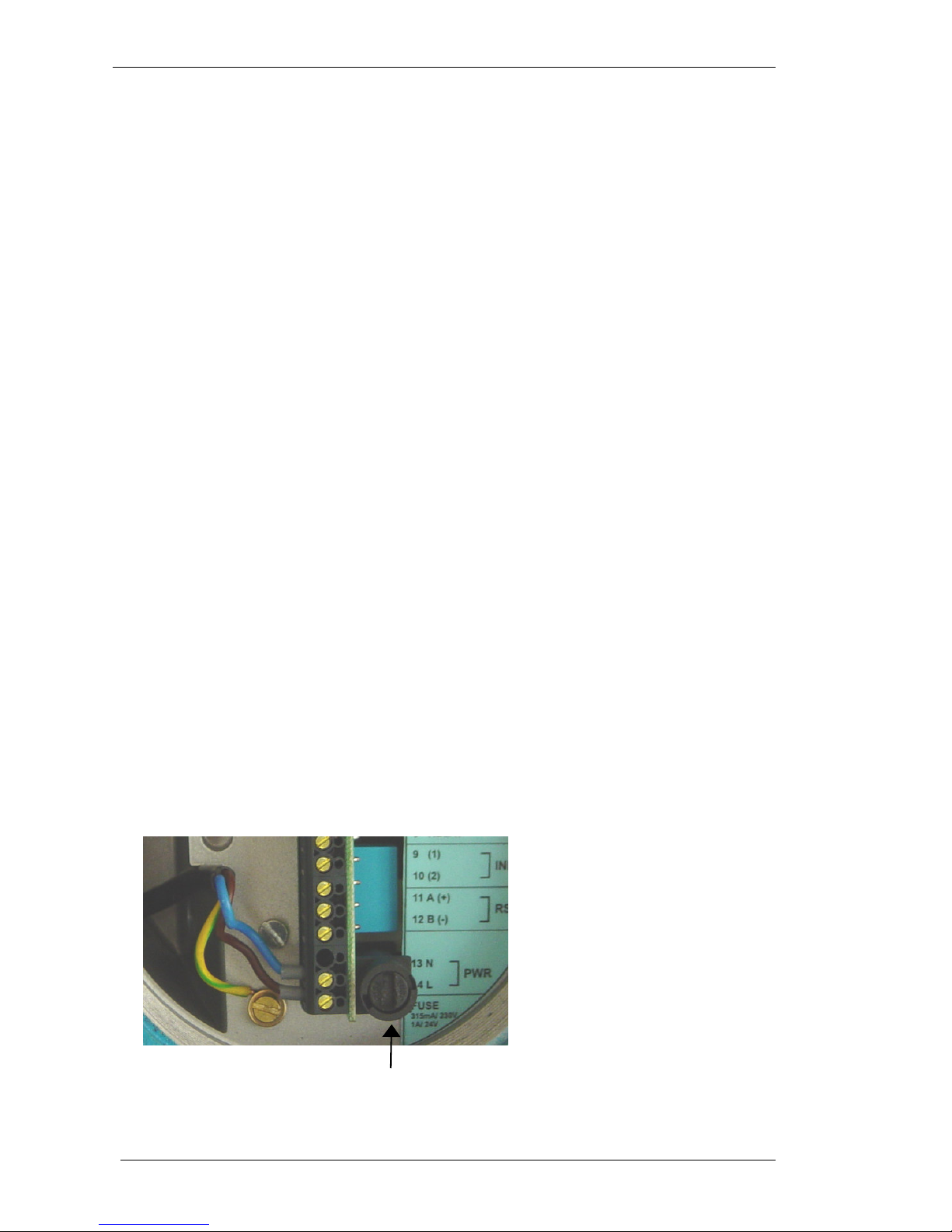
2.2
Fuse replacement ____________________________________________________________6
2.3
Power supply ________________________________________________________________7
3Installation ____________________________________________________________ 8
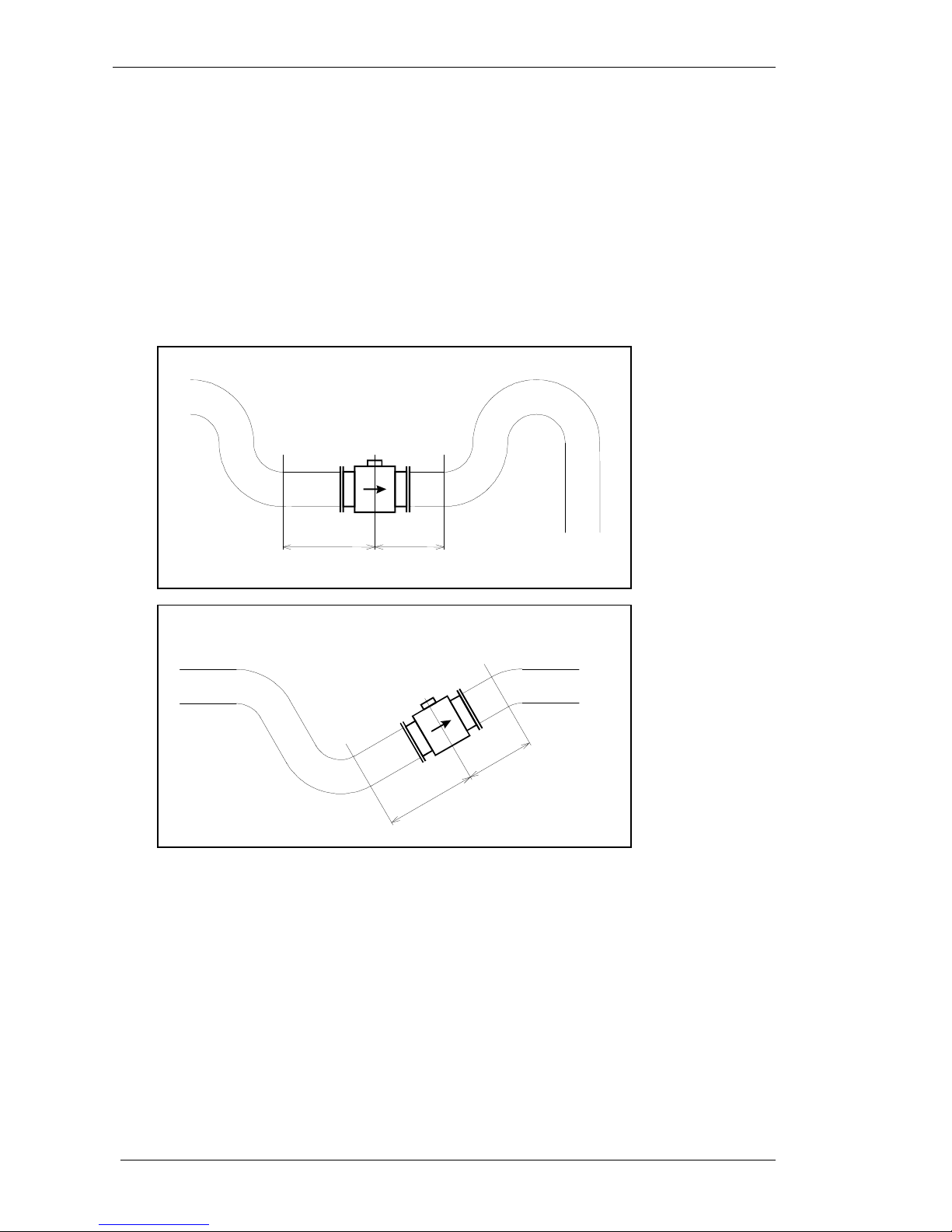
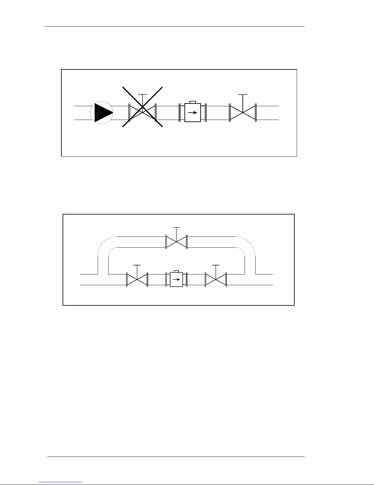
3.1
Sensor location ______________________________________________________________8
3.2
Electrical connection ________________________________________________________11
3.2.1
Compact version ______________________________________________________________ 11
3.3
Sensor grounding ___________________________________________________________12
3.4
Turning the display panel _____________________________________________________12
4Electronic unit description _______________________________________________ 13
4.1
Front panel (display)_________________________________________________________13
4.2
Rear panel (inputs/outputs) ___________________________________________________14
4.3
Signal terminals ____________________________________________________________15
4.3.1
Current loop output____________________________________________________________ 15
4.3.2
Frequency output______________________________________________________________ 16
4.3.3
Impulse output ________________________________________________________________ 16
4.3.4
Status output _________________________________________________________________ 17
4.3.5
PLC digital input ______________________________________________________________ 17
4.3.6
Serial port RS485______________________________________________________________ 17
4.4
Serial port RS232 ___________________________________________________________19
5Operation_____________________________________________________________ 20
5.1
Main menu ________________________________________________________________20
5.1.1
Current Flowrate / Total Volume_________________________________________________ 20
5.1.2
Positive Volume _______________________________________________________________ 20
5.1.3
Negative Volume ______________________________________________________________ 20
5.1.4
Auxiliary Volume______________________________________________________________ 20
5.1.5
Maximum Flowrate / Maximum Flowrate Time_____________________________________ 20
5.1.6
Minimum Flowrate / Minimum Flowrate Time _____________________________________ 20
5.1.7
Datalogger ___________________________________________________________________ 21
5.2
Setup menu ________________________________________________________________21
5.2.1
Input and outputs configuration (1 INPUT/OUTPUT) _______________________________ 21
5.2.1.1
Current loop output (1.1 CURRENT)___________________________________________ 21
5.2.1.2
Frequency output (1.2 OUTPUT F) ____________________________________________ 22
5.2.1.3
Impulse output (1.3 OUTPUT P) ______________________________________________ 23
5.2.1.4
Pulse width (1.4 PULSE WIDTH)______________________________________________ 24
5.2.1.5
Status output (1.5 OUTPUT S)________________________________________________ 24
5.2.1.6
PLC digital input (1.6 INPUT) ________________________________________________ 25
5.2.1.7
Low flowrate limit (1.7 LIMIT PF1) ___________________________________________ 26
5.2.1.8
High flowrate limit (1.8 LIMIT PF2) ___________________________________________ 26
5.2.1.9
Hysteresis of flowrate limits (1.9 HYSTERESIS) _________________________________ 26
5.2.1.10
RS485 baud rate (1.A RS485 B.R.) ____________________________________________ 26
5.2.1.11
RS485 address (1.B RS485 ADDR.) ___________________________________________ 27
5.2.2
Flowmeter configuration (2 FLOWMETER) _______________________________________ 27
5.2.2.1
Flowrate units (2.1 FLOW UNIT) _____________________________________________ 27
5.2.2.2
Flowrate resolution (2.2 FLOW RESOL.) _______________________________________ 27
5.2.2.3
Volume units (2.3 VOLUME UNIT) ___________________________________________ 28

Electromagnetic flowmeter M910
Operation manual 3
5.2.2.4
Volume resolution (2.4 VOL. RESOL.) _________________________________________ 28
5.2.2.5
Flowrate direction (2.5 FLOW DIREC.) ________________________________________ 28
5.2.2.6
Low-flow cutoff (2.6 L.F.CUTOFF) ____________________________________________ 29
5.2.2.7
Moving average time constant (2.7 TIMECONST)_________________________________ 29
5.2.2.8
Time setting (2.8 TIME SET.)_________________________________________________ 29
5.2.2.9
Date setting (2.9 DATE SET.)_________________________________________________ 29
5.2.2.10
Datalogger setting (2.A DATALOGGER)________________________________________ 29
5.2.3
General settings (3 GENERAL) __________________________________________________ 30
5.2.3.1
Diameter (3.1 DIAMETER) __________________________________________________ 30
5.2.3.2
Nominal flowrate range Q
N
(3.2 RANGE) _______________________________________ 30
5.2.3.3
Serial number (3.3 SERIAL NR.)______________________________________________ 30
5.2.3.4
Power supply (3.4 POWER SUP.) _____________________________________________ 30
5.2.3.5
Self-test (3.5 SELFTEST) ___________________________________________________ 30
5.2.3.6
Current Loop Test (3.6 C.LOOP TEST)_________________________________________ 30
5.2.3.7
Basic Menu Password (3.7 PASSWORD MN.) ___________________________________ 31
5.2.4
Calibration menu (4 CALIBRATION) ____________________________________________ 31
5.2.4.1
Number of Calibration Points (4.1 NR.OF CALP.) ________________________________ 31
5.2.4.2
Calibration point 1 (4.2 CAL.POINT 1) _________________________________________ 31
5.2.4.3
Calibration point 2 (4.3 CAL.POINT 2) _________________________________________ 32
5.2.4.4
Calibration point 3 (4.4 CAL.POINT 3) _________________________________________ 32
5.2.4.5
Calibration point 4 (4.5 CAL.POINT 4) _________________________________________ 32
5.2.4.6
Calibration Password (4.6 PASSWORD CA.) ____________________________________ 32
6System control _________________________________________________________ 34
6.1
RS485 bus properties ________________________________________________________ 34
6.2
RS232 bus properties ________________________________________________________ 34
6.3
Command syntax ___________________________________________________________ 34
6.4
Command list ______________________________________________________________ 35
7Error messages ________________________________________________________ 47
8Maintenance __________________________________________________________ 48
8.1
Advice for correct operation __________________________________________________ 48
8.2
Periodical maintenance ______________________________________________________ 48
8.3
What to do in case of failure __________________________________________________ 48
9Application information _________________________________________________ 49
9.1
Weight and dimensions ______________________________________________________ 49
9.1.1
Electronic unit – compact version ________________________________________________ 49
9.1.2
Pipe with sensor _______________________________________________________________ 49
9.2
Used materials _____________________________________________________________ 50
9.3
Flowrate versus diameter_____________________________________________________ 51
10 Type plate ___________________________________________________________ 52
11 Technical data _______________________________________________________ 54
12 Ordering information - options __________________________________________ 55
12.1
Example of order _________________________________________________________ 55
13 Terminology _________________________________________________________ 56
Appendix A Measuring principle ____________________________________________ 57
Appendix B M910 Menu structure ___________________________________________ 58

Electromagnetic Flowmeter M-910
4 Operation manual
1 Basic information
1.1 Basic features
The inductive flow meter M-910 is designed to measure, indicate and record the instantaneous and total flow of
the conductive media flowing through the sensor. The flow meter M-910 records both forward and reverse flows.
As there are no moving parts in the flow profile the M-910 can be used to measure extremely dirty liquids
containing solids. The only limitation is that the flowmeter can be used solely with conductive liquids.
Range of applications. The inductive flow meter M-910 is for use in the Chemical Industry, Paper Industry, Water
and Wastewater Treatment Industry and most other process industries.
Features. The inductive flowmeter M-910 is a highly accurate and stable device. The construction of the M-910
flowmeter uses components with long-term, time and temperature stability. Configuration data is backed up and
can be recovered after a power failure. The back-up structure enables data recovery even if a partial loss of data
occurs as a result of (e.g. high level electrostatic discharge or a noisy power supply). Internal CPU provides all
functions usually built in electronic flow meters, incl. low flow rate correction, frequency response setting,
bandwidth of sensitivity setting at low flow rates, etc.
Outputs. Flowmeter M-910 is equipped with 6 standard isolated outputs: 4 to 20mA either active or passive,
frequency output, impulse output, status (relays) output, RS485 and RS232 output. The user can configure both
frequency and pulse output.
Power supply. Both versions of the standard 115V/230V power supply and 24V DC/AC power supply are
available.
1.2 Standards and approvals
Electromagnetic flowmeter is conformed to requirements for bearing CE mark.
• Electromagnetic flowmeter electronic unit, both remote and compact version meet safety requirements
according to standard EN 61010-1 including amendment A2.
• Electromagnetic flowmeter electronic unit, both remote and compact version meets EMC requirements
according to standard EN 61000-3, EN 61000-4, EN 61000-6
• Pipe with sensor meets requirements of Pressure Equipment Directive 97/23/EC.
• Both the pipe and electronic unit, meet the requirements of degree of protection provided by enclosure level
IP67, according to EN 60529 (IEC 529).

Electromagnetic flowmeter M910
Operation manual 5
1.3 Warranty
Within the manufacturers general supply conditions, all material and manufacturing faults are covered by that. It is
up to us whether the warranty obligation includes a repair free of charge or corresponding replacement. Place of
the warranty obligation is Czech Republic. Further claims on compensation, especially for loss of production or
resultant of damages, are strictly excluded.
Any defects caused by improper use are absolutely not included in the warranty. Excluded from warranty are also
expendable items (as i.e. accumulators, batteries, pushbuttons after attained life time, ribbons, etc.)
In case of a warranty claim the user is asked to give detailed description of the defect and also of the application
for which you use the product. This information is important in order to avoid time and cost extensive tests and for
the eventual achievement of warranty claims from our suppliers and sub-suppliers. For the item or instrument,
returned after the expired warranty time, repair or replacement on warranty can only be accepted, if manufacturer
has been informed in time that a warranty case has occurred.
Warranty period for all types of electromagnetic flowmeter is 24 months.
The flowmeter should only be used according to the
instructions described in this operating manual.

Electromagnetic Flowmeter M-910
6 Operation manual
2 Preparing for start up
2.1 Inspecting the contents of the package
Basic package includes the following items:
• Flanged sensor
• Electronic Transmitter (can be integral or remote)
• Spare fuse
• Operating manual.
• Calibration certificate
• Special wrench for opening the housing covers
• Magnet for control without opening the housing
The flowmeter is delivered ready for use after connecting to the power supply. Please check that it has been
correctly installed according to chapter “Installation”.
Only a power supply with the appropriate voltage and frequency should be used. The flowmeter can be supplied
with either 230/115V 50/60Hz, or 24V (12V, 48V) DC/AC power supply, see ordering information in chapter
“Power supply”.
2.2 Fuse replacement
A mains fuse is located behind the back cover. The fuse must only be exchanged by a competent person. Procedure
is as follows:
• Disconnect the power supply from the flowmeter.
• Unscrew the back cover using the special wrench (standard part of delivery).
• The fuse holder is located behind the back cover. Remove the fuse. Replace it with new fuse with the same
rating.
• Screw on the back cover.
• Reconnect the power supply.
Fuse holder

Electromagnetic flowmeter M910
Operation manual 7
Note:
• T315mA fuse is used for 115/230 V version
• 1A fuse is used for 24 and 48 V DC/AC versions
• 2A fuse is used for 12 V DC/AC version
2.3 Power supply
From a power supply point of view the flowmeter is delivered in four basic versions:
• 115/230V ( +10%, -20%), 50/60Hz, automatic switching
• 12V DC (+20%, -10%), 12V 50/60Hz (+10%, -10%)
• 24V DC (+20%, -10%), 24V 50/60Hz (+10%, -10%)
• 48V DC (+20%, -10%), 48V 50/60Hz (+10%, -10%)

Electromagnetic Flowmeter M-910
8 Operation manual
3 Installation
3.1 Sensor location
To avoid measuring errors due to gas/air entrainment or to a partly filled pipe, please observe the following:
Horizontal (standard) mounting
The sensor tube must always remain full. The best way to achieve this is to locate the sensor in a low section of
pipe, see the following picture. It is recommended to install the sensor in a section of straight pipe with at least 5
times the pipe diameter before sensor and 3 times after sensor.
Pipe reducers
If the pipe diameter is not the same as the diameter of sensor, then pipe reducers can be used. So as not to lose
accuracy of the measurement, the slope of reducers should not exceed 8°.
5 DN
3 DN
5 DN
3 DN

Electromagnetic flowmeter M910
Operation manual 9
Vertical mounting
When the sensor is mounted on a vertical section of pipe, the flow direction must be upwards. In the case of a
downward flow direction, air bubbles can collect in the sensor and the measurement could be unstable and
inaccurate.
Pumps
Never install the sensor on the suction side of a pump or on a section of pipe where a vacuum is possible.
8

Electromagnetic Flowmeter M-910
10 Operation manual
Valves
Suitable location of a shutoff valve is downstream of a sensor.
Removal during maintenance
If the application requires removal of the sensor for periodic maintenance, it is recommended to install a bypass
section as the following drawing.
Vibration
To avoid mechanical damage protect both electronic unit and sensor against mechanical vibrations. When strong
vibrations are possible, both the input and output pipe must be mechanically fixed or the remote version with a
separate electronic unit should be used.
Overheating
To avoid overheating, the electronic unit should be protected against direct sunlight especially in areas with a warm
climate with ambient temperatures over 30
o
C. If necessary a sunshade has to be mounted over the electronic unit
or a remote version with a separate electronic unit should be used.

Electromagnetic flowmeter M910
Operation manual 11
3.2 Electrical connection
Only a competent person may connect the flowmeter to the mains power supply.
The flowmeter can be connected to the power supply with either a fixed power cable or with a flying lead cable and
plug. Cable entries on the electronic unit can be used for flexible electrical cables. Cables with a diameter between
8 and 10 mm must be used to keep protection IP67. It is not recommended to use rigid metal or plastic conduits.
If you use a cable and plug it is recommended that the cable has a cross-section of 3 x 1.5mm
2
and with a minimum
length of 1 m.
In the case of a fixed connection an independent power switch or circuit breaker should be located close to the
flowmeter. Cable cross-section as above.
3.2.1 Compact version
To connect the compact version to the power supply the following procedure should be used.
• Unscrew the back cover using the special wrench (standard part of delivery).
• Connect the earth wire (yellow-green colour) to the central grounding point inside the case. The end of earth
wire must be hooked (app. 3 mm) and fixed to the earth screw.
• Connect Live and Neutral power cables to the power line terminal clamps with labels 14 (L-wire, brown
terminal colour) and 13 (N-wire, blue terminal colour).
• Screw on the back cover.
• Switch on the power supply.
Note:
Be careful to avoid following problems during electrical installation:
• Do not cross or loop cables inside electronic unit.
• Use separate cable entries for power supply and signal wires.
GND central grounding point L line wire
N line wire

Electromagnetic Flowmeter M-910
12 Operation manual
3.3 Sensor grounding
To ensure the correct operation of the flowmeter an earthing connection between the sensor and pipeline must be
made. The sensor is equipped with screw connection for an earthing wire. This screw has to be connected to the
flange on the pipeline. Use Copper wire to connect between the flange and the earth screw on the sensor.
If the pipeline is manufactured from a non-electrically conductive material, or if the pipe is lined with a similar
material, special grounding rings must be installed between flanges.
Note: The flowmeter must not be switched on, if the sensor is not connected /earthed to the rest of pipeline!
3.4 Turning the display panel
The flowmeter M910 display can rotated ± 90°.
Procedure is as follows:
• Disconnect the power supply from the flowmeter.
• Unscrew the back cover using the special wrench (standard part of delivery).
• Detach the two screws in the front plate and remove the plate.
• Unscrew next two legs and carefully turn the display.
• Reassemble in reverse order.
• Reconnect the power supply.

Electromagnetic flowmeter M910
Operation manual 13
4 Electronic unit description
4.1 Front panel (display)
1 RS232 connector
RS232 port enables you to connect the flowmeter to a personal computer. Serial port is galvanically isolated from
other electronic circuits.
2 Display
Two-row alphanumerical display is used for displaying all information. The instantaneous flowrate is displayed in
upper row. Total volume is displayed in the lower row.
The decimal point position and type of units can be changed in the flowmeter “Setup Menu” (see chapter
“Flowmeter configuration”).
3 Keyboard
4 keys enable you to change flowmeter configuration and provide flowmeter calibration. These are UP, DOWN,
ESC and ENTER keys.

Electromagnetic Flowmeter M-910
14 Operation manual
4 Magnetic sensor
All important displayed information can be read without
opening the flowmeter. The sensor display can be
activated by using a magnet. Activating the sensor (less
than 3 seconds) using a magnet is equal to pushing the
“UP” key. Activating the sensor (more than 3 seconds)
is equal to pushing “RIGHT” key.
4.2 Rear panel (inputs/outputs)
Under the back cover of the electronic unit are the terminals for input/output signals and supply terminals. The
fuse holder is located near the power supply terminals. The top cable gland is for input/output signals cable, bottom
cable gland for power supply cable.
Cable glands
Power supply
terminals
Signal
terminals
Fuse

Electromagnetic flowmeter M910
Operation manual 15
4.3 Signal terminals
4.3.1 Current loop output
The 4 to 20 mA current loop can be set as a passive type between outputs 1, 2 (1 positive, 2 negative) or as an
active type between outputs 2, 3 (2 positive, 3 negative). In both cases the outputs are galvanically isolated from all
other electronic circuits of the flowmeter. Voltage drop on passive current loop is 4 V. Active current loop can
work to a maximum of 800 Ω.
Example of current output connection:
For more information about current output see chapter “Input and outputs configuration”.
Current loop
Impulse output
Frequency output
Status output
PLC input
RS485 interface
Power supply
Passive
current output connection
Active
current output connection

Electromagnetic Flowmeter M-910
16 Operation manual
4.3.2 Frequency output
The frequency output is a galvanically isolated transistor NPN switch. Voltage drop on the switch is 1 V in the
made status. Maximum switched voltage is 50 V. Maximum switched current should not exceed 100 mA. Positive
output is on terminal 4, negative output is on terminals 5 and 7 (internally connected). Frequency range of the
output is from 10 Hz to 12 kHz.
Example of the frequency output connection:
For more information about frequency output see chapter “Input and outputs configuration”.
Note 1: Frequency, impulse and status outputs are galvanically connected to each other and galvanically isolated
from other electronic circuits.
Note 2: Active frequency output uses the power supply of the current output. Total current take-off from this
power supply (terminal nr. 1) must be less than 40 mA. Active frequency output is galvanically connected
to current output.
4.3.3 Impulse output
The impulse output is formed by a galvanically isolated transistor NPN switch. Voltage drop on the switch is 1 V
in the made mode. Maximum switched voltage is 50 V. Maximum switched current should not exceed 100 mA.
Positive output is on terminal 6, negative output is on terminal 5 and 7 (internally connected). Width of the impulse
can be set. Maximum frequency of impulse output is limited by impulse width. Maximum frequency is 50 Hz for
the shortest impulse 10 ms
Example of impulse output connection:
For more information about impulse output see chapter “Input and outputs configuration”.
Note 1: Frequency, impulse and status outputs are galvanically connected to each other and galvanically isolated
from other electronic circuits.
Passive
frequency output connection
Active
frequency output connection
Passive
impulse output connection
Active
impulse output connection

Electromagnetic flowmeter M910
Operation manual 17
Note 2: Active impulse output uses the power supply of the current output. Total current take-off from this power
supply (terminal nr. 1) must be less than 40 mA. Active impulse output is galvanically connected to
current output.
4.3.4 Status output
Status output is formed by relays. Maximum switched voltage is 100 V. Maximum switched current should not
exceed 500 mA. First output is on terminal 8, second output is on terminal 5 and 7 (internally connected).
Example of status output connection:
For more information about status output see chapter “Input and outputs configuration”.
Note 1: Frequency, impulse and status outputs are galvanically connected to each other and galvanically isolated
from other electronic circuits.
Note 2: Active status output uses the power supply of the current output. Total current take-off from this power
supply (terminal nr. 1) must be less than 40 mA. Active status output is galvanically connected to the
current output.
4.3.5 PLC digital input
The digital input is activated with a DC voltage between 5 and 30 V (positive or negative). The digital input is
between terminals 9 and 10.
For more information about digital input see chapter “Input and outputs configuration”.
Note: PLC digital input is galvanically isolated from other electronic circuits.
4.3.6 Serial port RS485
The serial port RS485 is assigned for online communication between flowmeter and computer. It is suitable for real
time flowmeter monitoring. In contrast to the RS232 serial port, which is suitable for one-shot configuration or
calibration of the flowmeter. The RS485 can be connected to up to 16 flowmeters together and the total connection
length of all wires can be up to 800 meters. Positive output (A) is on terminal 11, negative output (B) on terminal
12.
Example of three flowmeters and one computer interconnection:
Passive
status output connection
Active
status output connection

Electromagnetic Flowmeter M-910
18 Operation manual
All flowmeters and computer are connected parallel using twisted pair cable. At each end of the communications
line should be 470 Ωterminations.
Interconnection of three flowmeters and computer using RS485 bus
Flowmeters are marked with numbers. These numbers are equal to the flowmeters RS485 address.
Program Flow910 is designed for flowmeter control using RS485 or RS232 serial bus. It can be ordered as M900
option.
Note: Communication through the serial port RS485 is a half duplex type. The flowmeter is a listener and sends
data only after a query from a computer. Each flowmeter has it’s own RS485 address. The range of
addresses is 0 to 255. Factory setting of RS485 address is 0. Communication speed is selectable between
1200 and 19200 Bd. For cables over 100m or if there is a noisy power supply voltage (especially peaks
generated, usually by motors, etc.), select communication speed below 9600 Bd.
Note: Serial port RS485 is galvanically isolated from other electronic circuits.
910 _ 1 910 _ 2 910 _ 3 PC
470
Ω
470
Ω

Electromagnetic flowmeter M910
Operation manual 19
4.4 Serial port RS232
The connector is located on the front panel and is accessible after removing the electronic unit cover. RS232
enables you to connect the flowmeter to a personal computer. RS232 interface is used for flowmeter configuration
and calibration. It’s not suitable for online communication during operation, because the flowmeter must be open
and IP67 protection is not valid. For such communication use RS485 interface.
For connection of the flowmeter to the PC a standard RS232 cable (1 : 1) can be used. To connect a PC to the
flowmeter, follow this procedure:
• Unscrew the front cover using the special wrench (standard part of delivery).
• Plug the one end of the RS cable onto the serial connector in the flowmeter.
• Connect the opposite end to the serial port in the PC.
• Use the application software (Flow910) to enter new calibration data or to change settings of the flowmeter.
• Disconnect RS232 cable and replace the cover.
RS-232 connector layout
Pin Label Direction
Note
2 TXD Output Transmitter
3 RXD Input Receiver
5 GND - Ground
9-pin connector D-SUB FEMALE
Cable between PC and Flowmeter (configuration 1:1)
PC D-Sub 1
D-Sub 2
M910
Transmitter 2 2 Transmitter
Receiver 3 3 Receiver
Ground 5 5 Ground
Note: Serial port RS232 is galvanically isolated from other electronic circuits.

Electromagnetic Flowmeter M-910
20 Operation manual
5 Operation
5.1 Main menu
The flowmeter is in Main menu after the switching power on or after repeatedly pushing the ESC key. This entire
menu can be operated with a magnetic without opening the housing. Short use of the magnet (less than 3 seconds)
is equal to pushing “UP” key. Longer use of the magnet (more than 3 seconds) is equal to pushing “RIGHT” key.
The following information can be displayed in the Main Menu.
5.1.1 Current Flowrate / Total Volume
Basic display (after power on). Current flowrate is displayed on the
first line. Total volume is displayed on the second line. Flow in the
forward direction is added to this volume, Flow in the reverse
direction is subtracted. Measuring parameters (units, resolution,
moving average etc.) are selectable in Setup menu. After pushing “UP” key “Positive Volume” is
displayed.
5.1.2 Positive Volume
Total volumetric flow in a forward direction. After pushing “UP”
key “Negative Volume” is displayed.
5.1.3 Negative Volume
Total volumetric flow in the reverse direction. After pushing “UP”
key “Auxiliary Volume” is displayed.
5.1.4 Auxiliary Volume
Second Total Volume counter. Can be cleared by pushing “RIGHT”
key. It is usually used for measuring volumetric flow during a set
period such as day, month etc.. After pushing “UP” key “Maximum
Flowrate” is displayed.
5.1.5 Maximum Flowrate / Maximum Flowrate Time
Maximum flowrate value indicated since last reset (pushing
“RIGHT” key). Date and time of maximum flowrate is displayed in
lower row. After pushing “UP” key “Minimum Flowrate” is
displayed.
5.1.6 Minimum Flowrate / Minimum Flowrate Time
Minimum flowrate value indicated since last reset (pushing
“RIGHT” key). Date and time of minimum flowrate is displayed in
lower row. After pushing “UP” key “Datalogger” is displayed.
Table of contents
Other Arkon Measuring Instrument manuals
Popular Measuring Instrument manuals by other brands

BW SENSING
BW SENSING WF-WK100 Technical manual

ENENSYS
ENENSYS Divi Catch RF user guide

Topcon
Topcon FC-500 owner's manual

PCB Piezotronics
PCB Piezotronics M3501B1260KG Installation and operating manual

Ohmic instruments
Ohmic instruments DM-509 Series instruction manual

PCB Piezotronics
PCB Piezotronics 357B21 Installation and operating manual