manuals.online logo
Brands
  1. Home
  2. •
  3. Brands
  4. •
  5. ARM Motorsports
  6. •
  7. Other
  8. •
  9. ARM Motorsports N63TU Operating and maintenance instructions

ARM Motorsports N63TU Operating and maintenance instructions

This manual suits for next models

1

Popular Other manuals by other brands

Opticon EduMic Compatibility guide

Opticon

Opticon EduMic Compatibility guide

Kessil A360W owner's manual

Kessil

Kessil A360W owner's manual

TEFAL ULTRA COMPACT MIXER manual

TEFAL

TEFAL ULTRA COMPACT MIXER manual

Martin Audio WS18X - SCHEMATICS manual

Martin Audio

Martin Audio WS18X - SCHEMATICS manual

Hendrickson AR2 series Service instructions

Hendrickson

Hendrickson AR2 series Service instructions

GO Industries 38017 installation instructions

GO Industries

GO Industries 38017 installation instructions

Cissell 30LBCMAN2 manual

Cissell

Cissell 30LBCMAN2 manual

RIDGID K-60SP manual

RIDGID

RIDGID K-60SP manual

Gage Bilt GB751SH-5 Original instructions

Gage Bilt

Gage Bilt GB751SH-5 Original instructions

OVE SIERRA 60 installation manual

OVE

OVE SIERRA 60 installation manual

ReelCraft 7800 OLB21 operating instructions

ReelCraft

ReelCraft 7800 OLB21 operating instructions

Body Armor 4x4 ECO-SERIES user manual

Body Armor 4x4

Body Armor 4x4 ECO-SERIES user manual

ROBLIN DROP Dimensions

ROBLIN

ROBLIN DROP Dimensions

EMG EMG-ACB BARREL Installation information

EMG

EMG EMG-ACB BARREL Installation information

MiniSolar MT-150 Assembling Guide

MiniSolar

MiniSolar MT-150 Assembling Guide

Parkside PSZ 250 B2 Operation and safety notes

Parkside

Parkside PSZ 250 B2 Operation and safety notes

ABB REM 610 Technical reference manual

ABB

ABB REM 610 Technical reference manual

Tyent ACE-13 user manual

Tyent

Tyent ACE-13 user manual

manuals.online logo
manuals.online logoBrands
  • About & Mission
  • Contact us
  • Privacy Policy
  • Terms and Conditions

Copyright 2025 Manuals.Online. All Rights Reserved.

N63 N63TU DOWNPIPES INSTALLATION GUIDE
TOOLS: 6mm Socket, 8mm Socket, 11mm Socket, 13mm Deep Socket, 15mm Deep Socket
O2 Sensor Socket, 6mm Hex Socket/Allen Key, E8 External Torx, E10 External Torx
12" Extension and Swivel Adapter, Adustable Wrench, Flathead Screwdriver, T30 Torx Bit
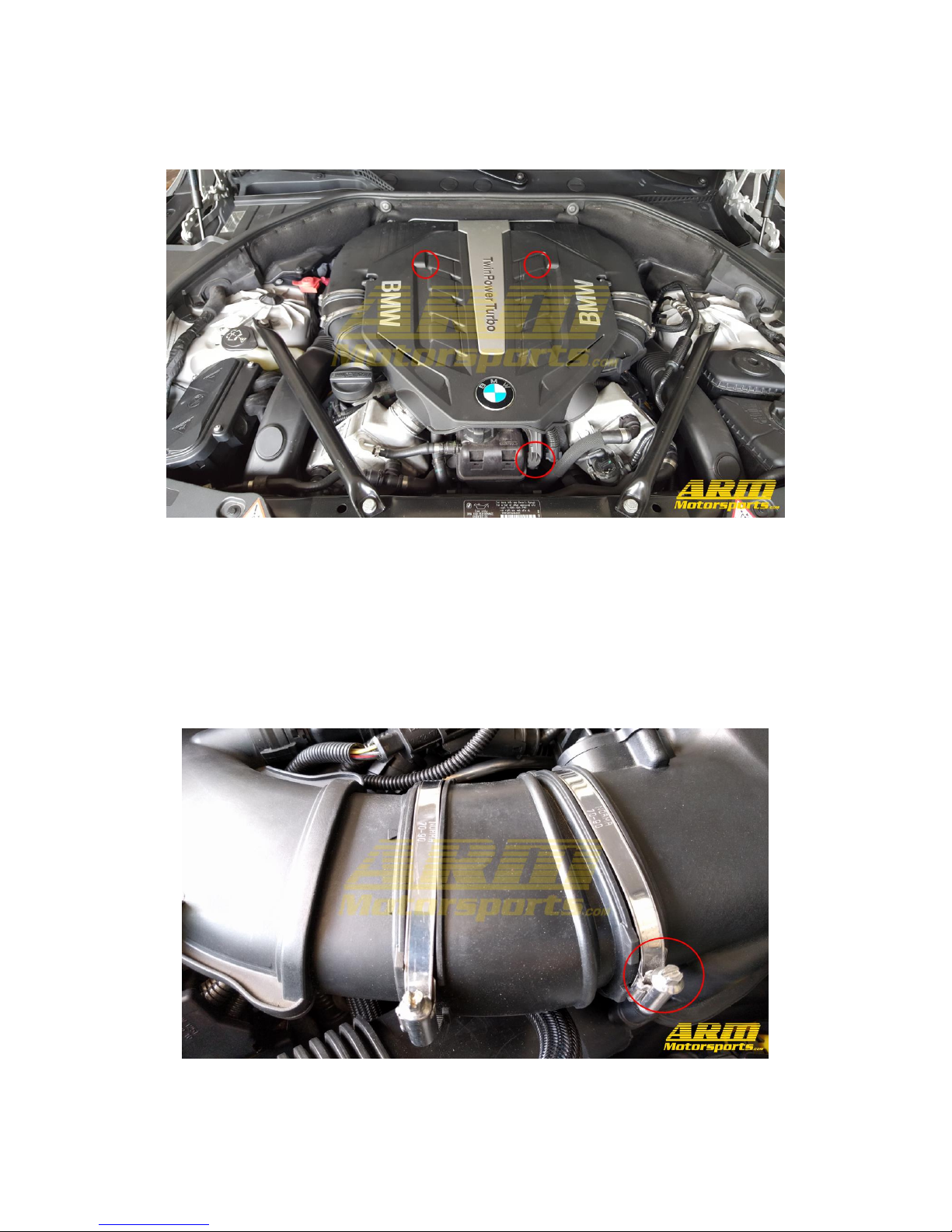
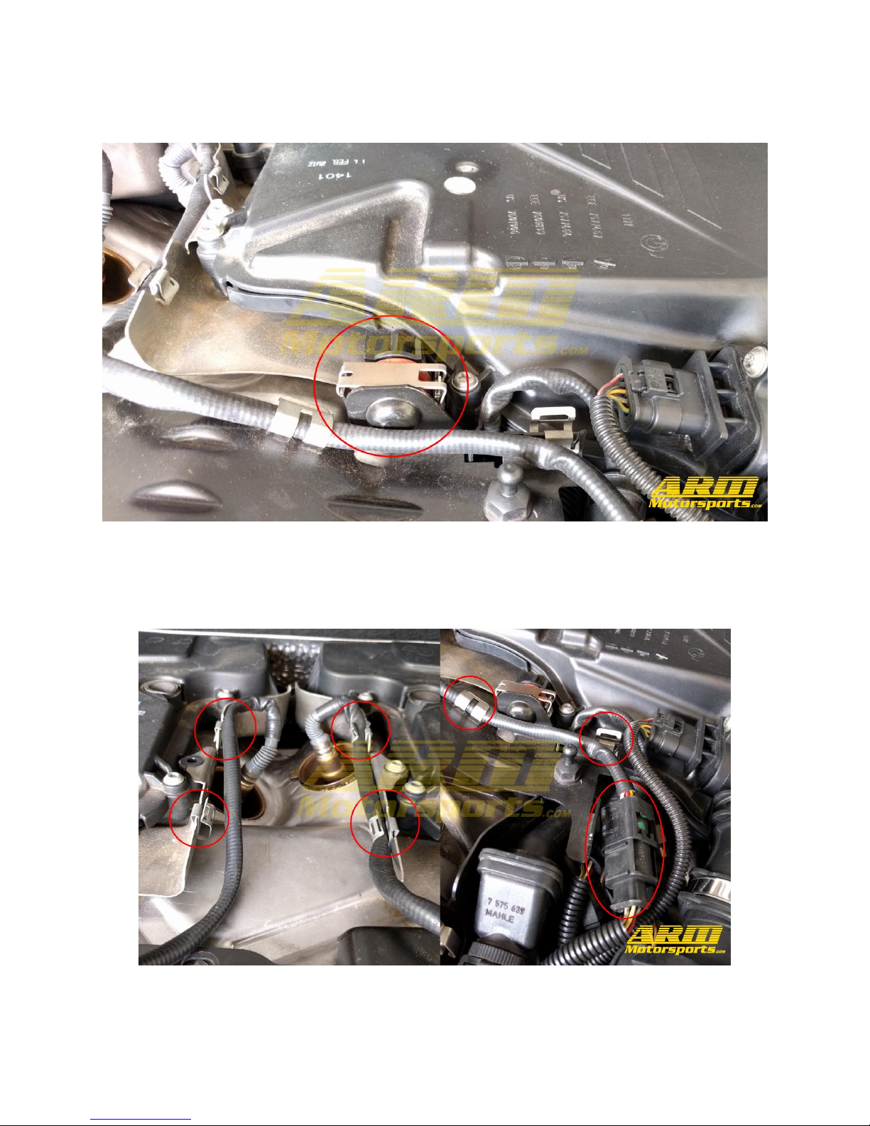
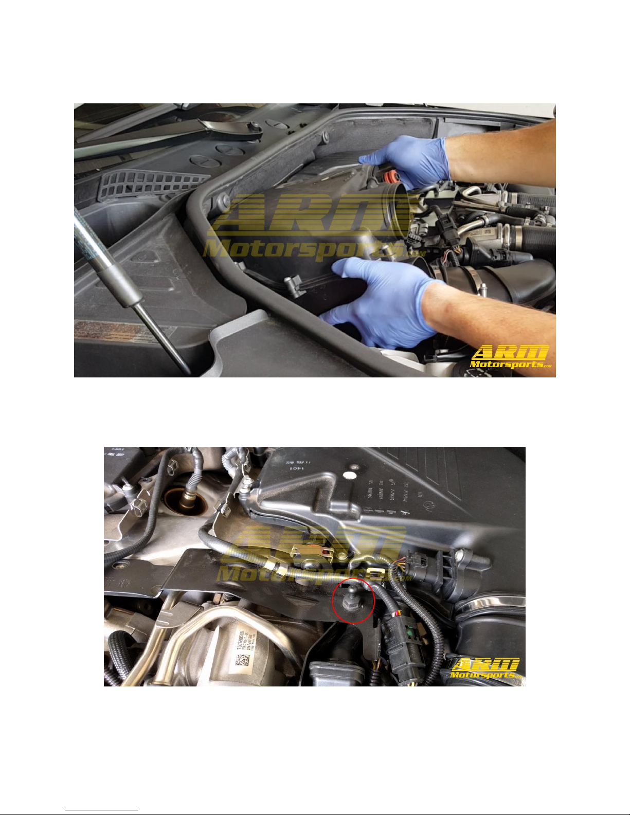
PHASE 1: REMOVE INTAKE
For those of you lifting the vehicle the old fashioned way this installation will only require the front end
of the car to be lifted off of the ground. That said, never work on a car being supported only by a jack.
Always utilize jack stands that meet the weight requirements of your vehicle.
STEP 1: Remove the factory engine cover by pulling up on the anchor points. There is one at the front of
the engine and two near the back.
STEP 2: With the factory intake exposed we will need to loosen the 6mm clamp on the intake hose on
each side.
STEP 3: Disconnect the airflow sensor on each side of the intake by pressing the tab and pulling away.
Leave the sensor inserted in the air filter box to protect it.
STEP 4: Disconnect the lower air tube on the air filter box. This is can be done by using a flat head
screwdriver to pull the plastic away from the clip shown in the image.
STEP 5: Undo the clasp holding in the portion of the intake with the orange rubber grommet on it by
using your flathead screwdriver.
STEP 6: We can now disconnect the four O2 sensor connections and remove the harness's from the clips
around the intake box.
STEP 7: With the air filter box now unattached to anything we can remove it by pulling up to pop it off of
the mounts holding it on underneath.
PHASE 2: REMOVE FACTORY DOWNPIPES
STEP 8: Remove the metal bracket on the top of the engine by using a deep 13mm socket to loosen the
bolt on each side.
STEP 9: Disconnect the topside O2 sensors using an O2 sensor socket and remove them and their copper
cups.
STEP 10: We'll begin removing the heat shield by loosening the 3 E8 sized external torx bolts on each
side. It is helpful to have an extension for this.
STEP 11: There are an additional 3 on the back side. In total there are 9 bolts which need to be removed.
Once they are removed the heat shield can be lifted out.
STEP 12: Uninstall the 3 bolt brace on each downpipe using a 6mm hex socket.
STEP 13: There are another two 6mm hex bolts on each side holding the downpipe to the back of the
engine which need to be removed.
STEP 14: Remove the vband clamps holding the downpipes to the turbos using a 13mm socket.
STEP 15: Using an adjustable wrench loosen and remove the lower O2 sensor on each side.
STEP 16: Going underneath the vehicle we are going to remove the first portion of the undertray using
an 8mm socket.
STEP 17: With this section of the undertray removed the metal splash guard is exposed. This is held on
with 13mm bolts. When all the bolts are removed slide it towards the rear of the vehicle for it to drop
out.
STEP 18: Next remove the third portion of the undertray which is held in with 8mm screws like the first
portion was.