Timbren AXLE-LESS Service manual

IMPORTANT NOTE
u
u
u
The Axle•Less suspension provides many advantages
and permits many innovative designs for trailers. There is no
thru axle and therefore the two sides of suspension are
completely independent. The absence of an axle tube,
however, means there will need to be comparable
strengthening of the trailer frame, especially at the areas where
the suspension is installed. The function of a regular axle as a
structural member must be compensated by strengthening /
reinforcing the trailer frame itself to prevent excessive bending
or twisting of the frame. At the very least this should mean that
the top plate of the suspension frame bracket be fully supported
and firmly fastened (bolted/welded) to robust cross members
of the frame or to the inboard extension of the frame rail itself or
both. Timbren will not be responsible for damage caused by
(1)
insufficient strengthening of the frame .
Use extra caution in case you need to disassemble the
suspension; be aware that both Aeon rubber springs (Jounce
and Rebound) are factory pre-loaded.
Axle•Less suspensions are NOT recommended for tri-
axle applications.
1. Install outboard arm on control arm using 4 bolts and
washers and shims as required (verify that bolts are grade
8). Fig. 1 shows what the right hand side should look like;
the left hand side is the mirror image. Torque fasteners to
90-95 ft-lbs (122-129 N.m). Skip this section if outboard
arm is factory pre-assembled.
Procedure:
Page 1
Installation Instructions
Procedure:(Cont.)
3. Locate the left hand and right hand side hangers on
frame rails, opposite to each other. Move hangers along
frame until center of spindles line up with marks on the frame
rails, viewing from top (fig. 2). Clamp hangers to frame.
Measure and compare distances “A” and “B”. Reposition
hangers until the difference between “A” and “B”
measurements is less than 1/8” (3 mm).
4. Be aware that the suspension has factory toe-in angles
built in. The correct alignment can be obtained ONLY if
frame and its crossmembers or mounting surfaces to the
suspension are perfectly square and they are sufficiently
strong to remain square under maximum loads. Slight
camber adjustments and corrections may be necessary by
using the shims between the outboard arm and control arm
before tightening the 4 bolts.
Fig. 2 Spindle Alignment (View from the top)
2. Make sure frame is perfectly square. Measure and
compare the diagonal distances from one corner of
frame to the opposite corner. Also measure and compare
the distances from the hitch to each rear corner of frame.
Ideally the measurements are identical (in each case the
difference should be less than 1/8” (3 mm).
Mark frame rails where centerline of spindles (wheels)
(2)
should cross frame (fig. 2) .
(1) To add rigidity to the trailer frame structure we recommend using rectangular-shape or fabricated box-form steel sections combined with crossmembers of larger
sizes; ultimately it will be the trailer manufacturer's responsibility to make sure that the frame is strong enough to be used with the AxleLess suspension.
(2) Be aware that the driver side and passenger sides have their own factory built-in camber and toe-in angles and therefore the two spindles do not need to be
exactly parallel.
Control Arm
Hitch
Frame Rail
A=B
Frame Rail
Front
of
Trailer
AB
Centerline of trailer
Left hand side Right hand side
Y
Y
Y
Y
Y=Y
Mark Frame Rails
Hub Face
Hub Face
Fig. 1 :
outboard arm
to control arm
(Right hand side)
Assembly of
Front
Hanger
Outboard Arm
Alignment
Shim
Typical Installation

Page 2
Installation Instructions
Insert a
suspension
crossmember
(not supplied)
Fig. 4 : Suspension crossmember installed
Fig. 3 : Reinforcing frame
(3) Welding the hanger is optional (instead of bolting it), but be aware that all paint around welding edges need to be ground off prior to welding. Protect Aeon®
rubber spring from extreme heat generated during welding.
Weld crossmember
to hanger
(4) When bolting the frame be aware that hollow (tubular) sections of frame may not be sufficiently strong to withstand compression of bolted joints and therefore
may collapse unless they are reinforced; consider fabricating a bracket similar to the one shown in fig 3 which has a clamp plate to go between the nut/head of bolt
and tube. Such bracket must be rigid enough to allow you to apply a full torque to bolts.
(3) (4)
5. Bolt hanger side plate: (fig. 3): Use holes in the hanger
side plate as a template (3 holes). Drill horizontal holes to the
side of frame at each side of trailer. Use ½ ” UNC Gr 8 bolts,
lock-nuts, and washers to mount hangers to frame (fasteners
are not included). Torque mounting bolts to 90-95 ft-lbs (122-
129 N.m).
6. Do either 6a or 6b (whichever is easier or more practical):
(3)
6.a) Bolt hanger top plate to frame : Hanger top plate must
be in full contact with the frame so that it can be bolted to
frame. Use holes in the hanger top plate as a template and
drill vertical holes (note that two ½”nuts are tack welded
inside hanger . In case frame is not wide enough, hanger top
plate can be bolted to crossmembers of frame instead (as
long as those crossmembers are strong enough). If
crossmembers exists but there is a gap between bottom
surface of crossmembers and top of hanger then steel
spacers (plates) should be used to fill up the gap. Drill
common holes to bolt hanger to crossmembers. Use ½ ”
UNC (grade 8) bolts and washers to mount hanger
top plate to frame (fasteners are not included). Make sure
bolts are long enough the entire length of nuts but they are
not too long to interfere with other parts of suspension in the
hanger. If trailer does not have crossmembers (but frame
main beam itself is sufficiently strong to overcome torsion of
frame) then fabricate an inboard extension and attach it to
the frame. Reinforce it by gussets as necessary (fig. 3)
to make it rigid.
6.b) Skip procedure (6.a) and install a simple suspension
crossmember if one or more of the following applies:
- You are retrofitting axles / suspensions on a standard
trailer;
- The design of the trailer does not allow drilling vertical
holes for bolting hanger top plate;
- Frame could be aluminum; creating frame inboard
extension may not be practical;
- Frame crossmembers may not be located directly above
hanger top plate and modifying or relocating them is not
optional procedure:
Use a 2"x2"x 1/4” (minimum) structural steel tube
section. Measure width of trailer and saw cut a piece to
that length. Slide tube through corresponding opening in
the driver and passenger-side hangers. Drill two holes at
each end and bolt suspension crossmember to hanger
weld it at each end (fig. 4).
7. Remove clamps.
Procedure:(Cont.)
Position gussets and
weld them to clamp plate
Drill
vertical
holes
Drill horizontal
holes
Use
stover
flange
nut here
or a
Locknut
and a
washer.
Inboard extension plate
(not supplied)
Weld
1/2” UNC
Fasteners to mount
Suspension / Hanger
to Frame
(not supplied)
Outboard
Inboard
Frame Rail
Hanger
Clamp
plate
(Not supplied)
Clamp
plate
(Not supplied)
Typical Installation
Page 3
(a)
Maintenance
PRIOR to doing any repair, inspection, or maintenance work under the trailer:
1. Park the trailer on solid, level ground such as a concrete or paved surface. Place the vehicle in park,
set the emergency brake and use wheel chocks to prevent the vehicle from moving.
2. No work may be done under any vehicle supported only by a hydraulic or mechanical jack.
3. Additional safety devices such as jack stands are required in order to provide extra protection.
Within the first week of operation:
- Retorque outboard arm (outboard arm) bolts to 90-95 ft-lbs (122-129 N.m).
- Retorque control arm pivot bolts to 430-470 ft-lbs (583-638 N.m).
- RetorqueALLbolts that are used to mount the hanger to frame (2 vertical bolts & 2 to 3 horizontal bolts)
to 90-95 ft-lbs (122-129 N.m).
- Lift the trailer, turn wheels individually by hand and make sure they are running smoothly and there is no slack
in the wheels when moved side to side. Tighten hub nut to take the slack out and re-check.
Periodic maintenance (once after 4 months and then every 12 months afterwards or sooner)
Do a complete visual inspection of the suspension / hubs. Inspect all metal components, hangers, control
arms, outboard arm and frame for cracks, deformed surfaces or broken welds. Check the bearings.
Repair or replace according to the manufacturers recommendations.
Check the alignment. Check that all bolts are tightened to a torque specified.
Repack bearings and hubs with new grease. Spinning the bearing during grease application is often
recommended to evenly coat the bearing. Replace grease seals if necessary.
(a) Parts of this document regarding the installation and maintenance of hubs are applicable ONLY if hubs are supplied by Timbren Industries Inc.
Typical Installation
Page 4
(a)
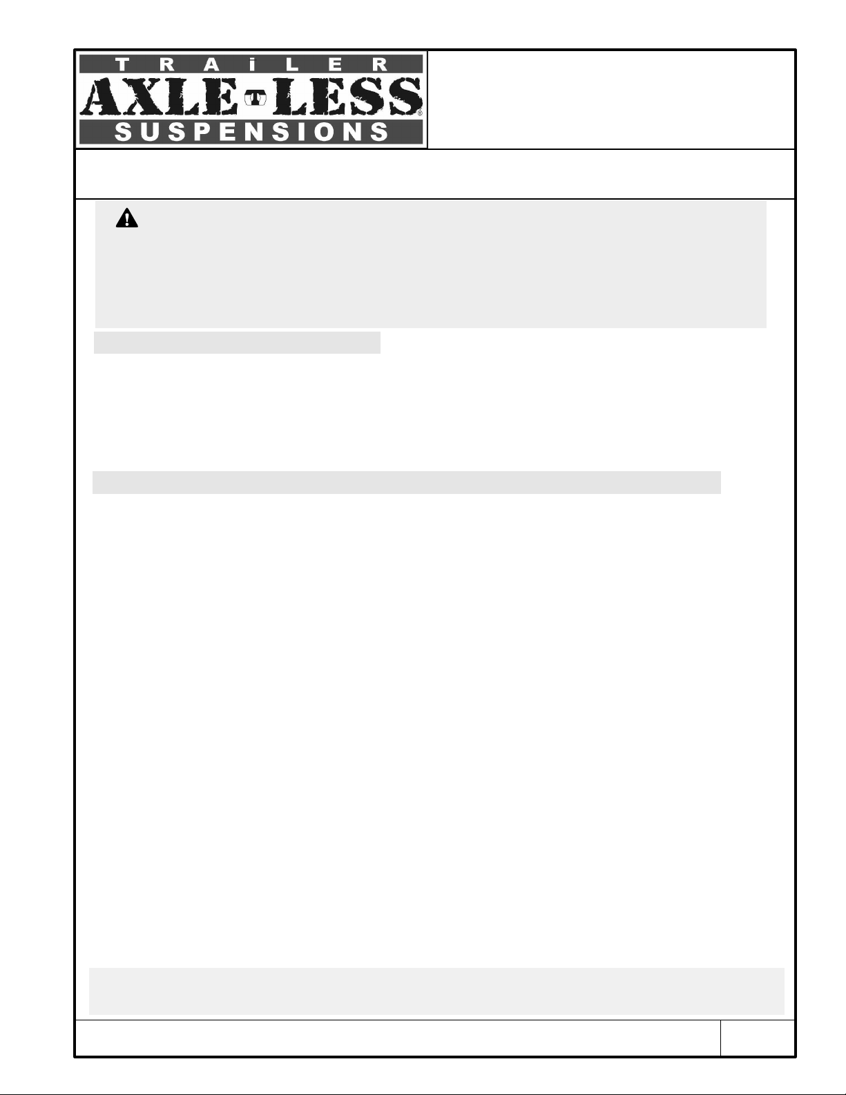
Installation of Idler Hubs
(a) Parts of this document regarding the installation and maintenance of hubs are applicable ONLY if hubs are supplied by Timbren Industries Inc.
(b) Use a high temperature automotive type wheel bearing grease. We recommend using Lithium complex type products with NLGI consistency of 2, with additives for
EP (extreme pressure), corrosion and oxidation, dropping point of 419° F (min.) (or 215° C), with minimum viscosity index of 80.
(c) Always use NEW cotter pins (8).
Typical 5 Bolt Idler Hub Assembly
Fig. 1
Inboard
Outboard
b
( )
Grease inner and the outer bearings ((3)&(5)) . Insert inner bearing in its housing on the inboard side of
hub (4) . Insert the grease seal (2) on top of the bearing and make sure it is fully seated. Turn hub around,
lift it and place it on the spindle (1) and slide it over into place. Insert outer bearing (5) . Put washer (6) and
install the castle nut (7) onto spindle. Tighten nut. Gently loosen it approximately 1/8 of a turn. Insert cotter
pin (8) through castle nut and spindle hole and then bend the end around the spindle with a screw driver or
plyers. Put the grease cap (9) and rubber plug (10) on.
12 4
3567 8 9 10
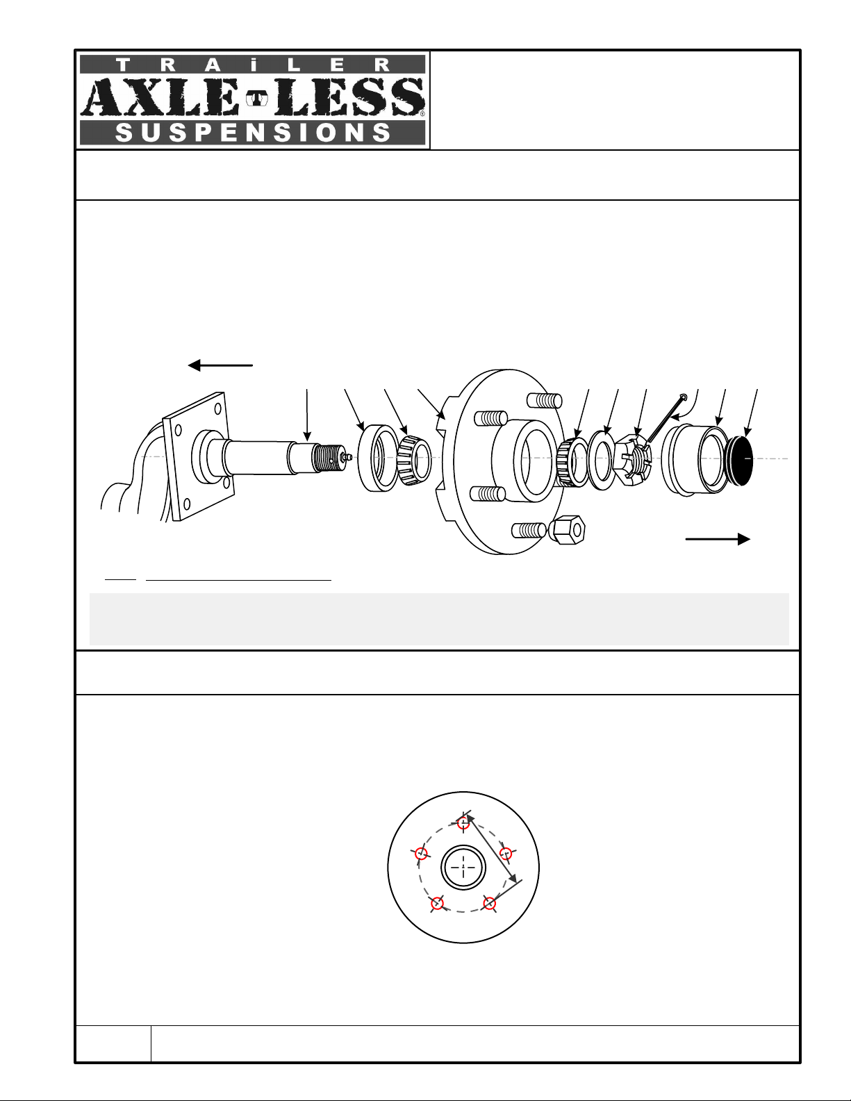
An easy way to estimate a 5 lug bolt circle
is to measure from the center on one hole
to the BACK of the third hole.
Identifying the bolt pattern of a hub
545 hub
545 hub = 5 bolts on a 4.5” bolt circle
The bolt circle is the diameter of an imaginary circle
formed by the center of the wheel hub
Typical Installation

Page 5
(a)
Installation of Hubs with Electric Brakes
(a) Parts of this document regarding the installation and maintenance of hubs and brakes are applicable ONLY if hubs and brakes are supplied by Timbren Industries Inc.
(b) Use a high temperature automotive type wheel bearing grease. We recommend using Lithium complex type products with NLGI consistency of 2, with additives for
EP (extreme pressure), corrosion and oxidation, dropping point of 419° F (min.) (or 215° C), with minimum viscosity index of 80.
(c) Always use NEW cotter pins (8).
Inboard
Outboard
Identify the left hand side (or L) and the right hand side (or R) brake (3A). You should be able to find either a
label inside each brake assembly or a note stamped on the body of the brake itself for the purpose of
identification. Install each brake to the backing plate of spindle arm at its corresponding side. The orientation
of brake is important: the magnet inside the assembly must be towards the bottom (the slack adjustor then,
will be at the bottom, brake shoe with shorter brake lining be at the front and the wires on the top).
Two wires on the inside of the backing plate must be connected to a brake controller which might be on either
the trailer or the tow vehicle (not supplied).
(b)
Grease inner and the outer bearings ((2A)&(2B)) . Insert inner bearing (2A) in its housing on the inboard side of
hub (3A) . Insert the grease seal (4) on top of the bearing and make sure it is fully seated. Turn hub around, lift
it and place it on the spindle (1) and slide it over into place. Position inner hub against the flange. Place five
7/16” lockwashers (#5) and five 7/16” UNF nuts (6) to mount each brake. Apply 50-55 ft.lbs (68-75 N.m) of
torque to each nut.
Position outer hub (3B) and insert outer bearing (2B). Put washer (7) and castle nut (8) onto spindle. Tighten nut
(8). Gently loosen it approximately 1/8 of a turn. Insert cotter pin (9) through castle nut and spindle hole and
then bend the end around the spindle with a screw driver or plyers. Put the grease cap (10) and rubber plug
(11) on.
Typical 5 Bolt Hub Assembly with Electric Brake
Fig. 2
1 4 3A
2A 3B 2B 7 8
10
13 11
9
5
6
12
Typical Installation
Table of contents
Popular Other manuals by other brands

Aqua Medic
Aqua Medic Powerfilter PF 1000 Operation manual

Edge Products
Edge Products Edge EZ Module Installation instructions and manual

Spectracom
Spectracom VersaSync Quick reference guide

Tetra
Tetra Test 6in1 Instructions for use

Goji
Goji GVREP18C instruction manual

Trotec
Trotec TTK 51 E operating manual


