Armstrong RADA MX1 Instruction manual

Rada Intelligent Care
MX1 Deck Mounted Tap
Installation Operation &
Maintenance Manual
495-EN V1.5
Please read and save these instructions

2
General. . . . . . . . . . . . . . . . . . . . . . . . . . . . . . . . . . . . . . . . . . . . . . . . . . . . . . . . . . . . . . . . . . . . . . . . . . . . 3
Important Safety Information. . . . . . . . . . . . . . . . . . . . . . . . . . . . . . . . . . . . . . . . . . . 3
Specification. . . . . . . . . . . . . . . . . . . . . . . . . . . . . . . . . . . . . . . . . . . . . . . . . . . . . . . . . . . . . . . . . . . . 4
Factory Default Settings . . . . . . . . . . . . . . . . . . . . . . . . . . . . . . . . . . . . . . . . . . . . . . . . . . 5
Pack Contents . . . . . . . . . . . . . . . . . . . . . . . . . . . . . . . . . . . . . . . . . . . . . . . . . . . . . . . . . . . . . . . . . . 8
Dimensions. . . . . . . . . . . . . . . . . . . . . . . . . . . . . . . . . . . . . . . . . . . . . . . . . . . . . . . . . . . . . . . . . . . . . . 9
Installation Requirements . . . . . . . . . . . . . . . . . . . . . . . . . . . . . . . . . . . . . . . . . . . . . . . 11
Installation. . . . . . . . . . . . . . . . . . . . . . . . . . . . . . . . . . . . . . . . . . . . . . . . . . . . . . . . . . . . . . . . . . . . . . . 12
Comissioning. . . . . . . . . . . . . . . . . . . . . . . . . . . . . . . . . . . . . . . . . . . . . . . . . . . . . . . . . . . . . . . . . . . 16
Operation. . . . . . . . . . . . . . . . . . . . . . . . . . . . . . . . . . . . . . . . . . . . . . . . . . . . . . . . . . . . . . . . . . . . . . . . . 17
Fault Diagnosis. . . . . . . . . . . . . . . . . . . . . . . . . . . . . . . . . . . . . . . . . . . . . . . . . . . . . . . . . . . . . . . . 19
Maintenance. . . . . . . . . . . . . . . . . . . . . . . . . . . . . . . . . . . . . . . . . . . . . . . . . . . . . . . . . . . . . . . . . . . . 25
Spare Parts. . . . . . . . . . . . . . . . . . . . . . . . . . . . . . . . . . . . . . . . . . . . . . . . . . . . . . . . . . . . . . . . . . . . . . 28
Limited Warranty and Remedy . . . . . . . . . . . . . . . . . . . . . . . . . . . . . . . . . . . . . . . . 32
Table of Contents

3
North America • Latin America • India • Europe / Middle East / Africa • China • Pacific Rim
armstronginternational.com
Make sure that the Rada MX1 is installed by a competent installer.
The product commissioning, clock (date/time) and tap set up can only be done in
conjunction with the “RADA AP1” available from the Apple App store. Time and
date setting is critical to ensure data reporting is correct.
The use of the word ‘failsafe’ to describe the function of any thermostatic mixing
valve is both incorrect and misleading. In keeping with every other mechanism it
cannot be considered as being functionally infallible.
Malfunction of thermostatic mixing valves can be detected by the use of proper
temperature checking and maintenance routines.
Certain types of system can result in the thermostatic mixing valve having
excessive ‘dead-legs’ of pipework. Such systems can disguise the onset of
thermostatic mixing valve malfunction. Ultimately, the user must exercise due
diligence to ensure that the delivery of warm water is at a stable, safe temperature
Make sure that the water delivery does not cause splashing or overflow.
Note: Clock settings are lost after a period of 24hrs without mains power.
When power is restored clock settings return to factory default (1st
February 2000) and will need to be reset via the App.
Shut off the main water and electrical supply.
Observe all local plumbing and building codes.
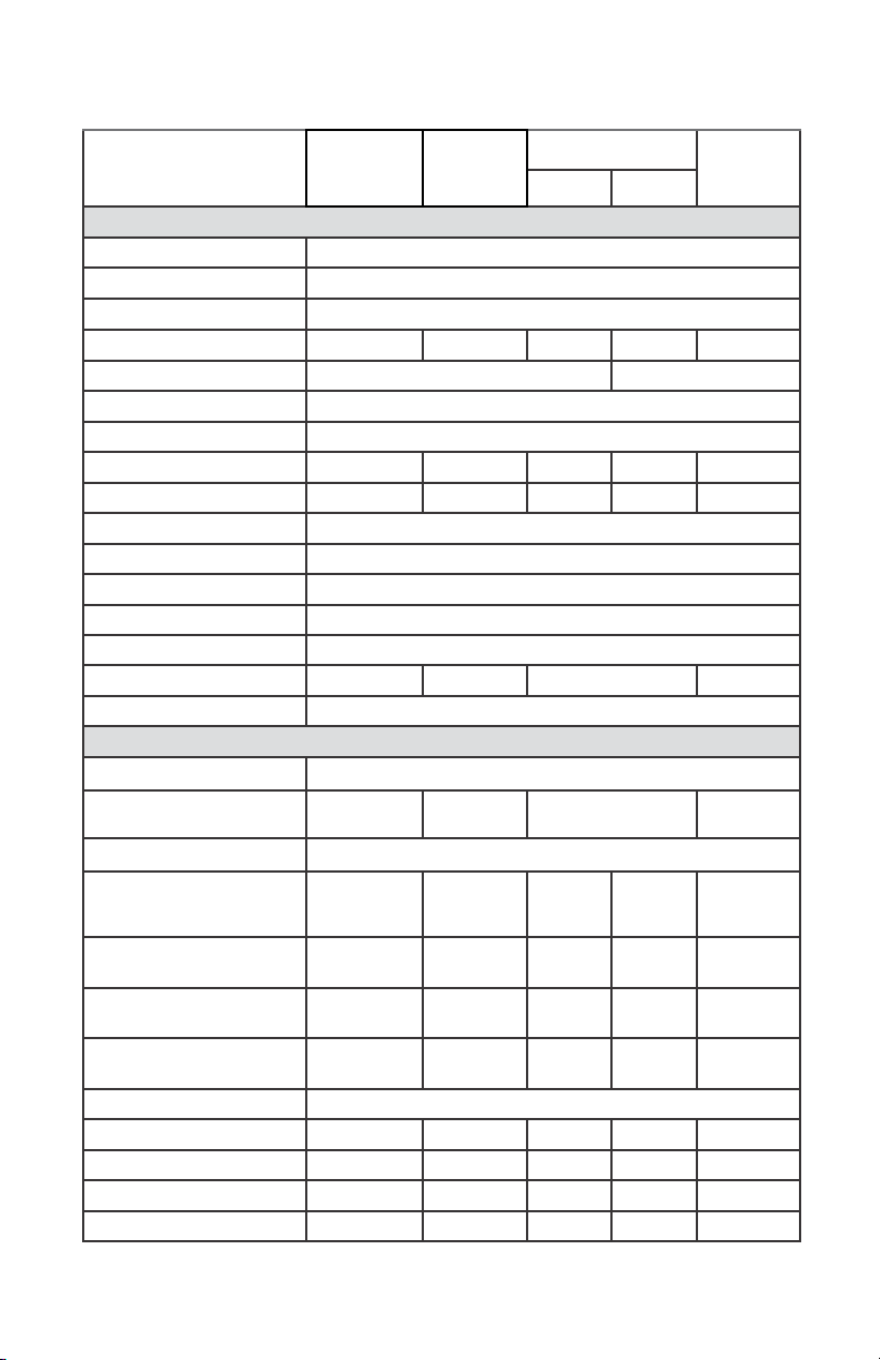
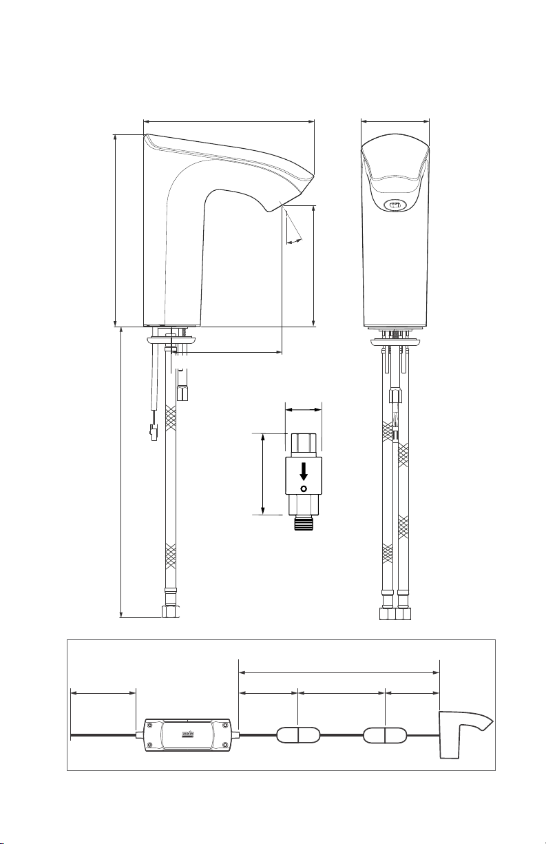
The Rada MX1 is a type 1, electronic, electrically operated, independently mounted
valve. It is intended for surface mounting and is for connection to the mains water
supply.
Isolator / Check valve / Filter housing supplied is an integral component of the tap,
failing to install will invalidate the product’s warranty.
The Rada MX1 must only be supplied from the power adaptor provided.
The power adaptor must be connected to the fixed wiring of the electrical supply
via a switched 3A fused spur.
If the power adaptor supply cord is damaged the power adapter must be replaced
by a competent person.
Where chlorine disinfection is practiced, DO NOT exceed a chlorine concentration
of 50 mg/l (ppm) in water, per one hour dwell time. Such procedures must
be conducted strictly in accordance with the information supplied with the
disinfectant and with all relevant Guidelines/Approved Codes of Practice.
Important Safety Information
General

North America • Latin America • India • Europe / Middle East / Africa • China • Pacific Rim
armstronginternational.com
4
For Type 3 installations, the supply conditions specified in the TMV3
Requirements Manual take precedence over the operating parameters which
follow.
General PSU Valve
Maximum Ambient Temperature 122°F (50°C) 104°F (40°C)
Minimum Ambient Temperature 33.8°F (1°C) 33.8°F (1°C)
Maximum Humidity 95% rH 95% rH
Electrical PSU Valve
Supply Voltage 100 - 240 V 50/60 Hz 12 V DC
Rated Input Current 1 A 2.0 A
Water Ingress Protection IP X4 IP X4
Protection Against Electric Shock Class II (double insulated) Class III (SELV)
Pollution Degree 2 2
Rated Impulse Voltage 2.5 kV 18 V
Performance
Factory pre-set temperature 102.2°F (39°C)
Factory pre-set temperature range 98.6°F - 105.8°F (37°C - 41°C)
Programmable temperature range 91.4°F - 113°F (33°C - 45°C) (Full cold can be selected
during programming)
Water Supply
Minimum dynamic pressure 14.5 Psig - 100 kPa (1.0 bar)
Maximum dynamic pressure 72.5 Psig - 500 kPa (5.0 bar)
Maximum static pressure 145.0 Psig - 1000 kPa (10.0 bar)
Supply pressure differential Equal pressure recommended - inlet pressures must
be stable for optimum performance.
Minimum recommended differential
between hot supply and outlet temp
(consistent with HSE Guidelines)
44.6°F (7°C)
Hot supply temp 131°F - 149°F (140F - 149°F Recommended)
55°C - 65°C (60°C - 65°C Recommended)
Cold supply temp 33.8°F - 77°F (1°C - 25°C)
Maximum disinfection temperature 176°F (80°C)
Specification

5
North America • Latin America • India • Europe / Middle East / Africa • China • Pacific Rim
armstronginternational.com
RADA App Tile / Section
Adjustable
Temperature
Varient
Fixed
Temperature
Varient
Range
Units
Min Value Max Value
1. Valve Setup / 4. Installation Setup
1. Setup Advice Info Field
2. Valve Identity Editable Text Field
3. Outlet Type and Sub Type Info Field
4. Unit Address 17 17 1 31
5. Valve Date and Time 24 Hr Clock DD/MM/YYYY
6. Last Service and Time Info Field
7. Flow Calibration
8. Minimum Flow Limit 5 5 1 100
9. Maximum Flow Limit 13 13 1 100
10. Valve DOB Info Field
11. Calibration N/A Set to max 300, 300
12. IR Calibration Factory Programmed - Typical Range 180 - 220
13. Pin 0001 - 9999 Permisable. Re-entry of 5945 Not Permitted
14. Tap Interface Info Field
15. Operational State Enable Enable Enable, Disable
16. Tasks Apply Changes to Valve/Undo Changes
1. Valve Setup / 5. Outlet Setup
1. Type Info Field
2. Sub Type On/Off On/Off (On/Off), Timed
Blocking N/A
3. Outlet Selection Info Field
4. Full Cold Mode Disabled Disabled Start Cold
Enabled
Disabled
Start Cold
Enabled
Disabled
5. Minimum Temperature 98.6°F (37°C) N/A 91.4°F
(33°C)
113 °F
(45°C)
32.9°F
(0.5 °C)
6. Default Temperature 102.2°F (39°C) 100.4°F
(38°C)
91.4°F
(33°C)
113 °F
(45°C)
7. Maximum Temperature 105.5°F (41°C) N/A 91.4°F
(33°C)
113 °F
(45°C)
32.9°F
(0.5 °C)
8. Flow Rate Setup N/A
9. Default Flow Rate 50 50 10 100 %
10. Outlet Timeout 5 Min 5 Min 0s 30 Min Seconds/min
11. Run on Time 5 S 5 S 1 60 Seconds
12. Temperature Memory 40 S N/A 0 5 Min Seconds/min
Factory Default Settings

North America • Latin America • India • Europe / Middle East / Africa • China • Pacific Rim
armstronginternational.com
6
2. Type Standard Standard
Disabled,
Standard,
Standard
oscillation
Disabled,
Standard,
Standard
oscillation
2. Type Standard Standard
Disabled,
Standard,
Standard
Oscillation,
Smart,
Smart
Oscillation
Disabled,
Standard,
Standard
Oscillation,
Smart,
Smart
Oscillation
3. Activation Time 02:00 Hrs 02:00 Hrs Time 24 Hr
Clock
4. Duration 1 Min 1 Min 1 S 25 min Seconds/Min
5. Frequency 1 Per 3 Days 1 Per 3 Days 1 Hr 1 Week Hrs/day/
1 Week
6. Schedule Auto Populated Field
7. Temperature 102.2°F (39°C) 102.2°F (39°C) 98.6°F
(37°C)
105.8°F
(41°C) deg F(C)
8. Flow Rate 100 100 10 100 %
9. Warm Up Time 1 Min 1 Min 1 S 25 Min Seconds/Min
10. Post Cold Flush 0 0 0 10 Seconds/min
11. Tasks Apply Changes to Valve/Undo Changes
1.Valve Setup / 7. Cold Flush Setup
1. Activation Manual Manual Manual, Automatic
2. Type Disabled Disabled Disabled, Standard
3. Activation Time 04:00 Hrs 04:00 Hrs Time 24 Hr
Clock
4. Duration 2 Mins 2 Mins 5 S 10 Mins Seconds/Min
5. Frequency 1 Per 3 Days 1 Per 3 Days 1 Hr 1 Week Hrs/Day/1
Week
6. Schedule Auto Populated Fiel d
7. Cool Down Temperature 66.2°F (19°C) 66.2°F (19°C) 59°F (15°C) <= Maintain
Temperature deg F(C)
8. Maintain Temperature 68°F (20°C) 68°F (20°C) 59°F (15°C) 86°F (30°C) deg F(C)
Factory Default Settings - continued
RADA App Tile/Section
Adjustable
Temperature
Varient
Fixed
Temperature
Varient
Range
Units
Min Value Max Value
13. Blocking Time 1 1 1 25 Min Seconds/min
14. Temperature Scale 9 Increments N/A 9, 5 Increments
15. Tasks Apply Changes to Valve/Undo Changes
1. Valve Setup / 6. Duty Flush Setup
1. Activation Manual Manual Manual, Automatic

North America • Latin America • India • Europe / Middle East / Africa • China • Pacific Rim
armstronginternational.com
7
Factory Default Settings - continued
RADA App Tile / Section
Adjustable
Temperature
Varient
Fixed
Temperature
Varient
Range
Units
Min Value Max Value
9. Cool Down Timeout 2 Mins 2 Mins 5 S 10 Mins Seconds/Min
10. Flow Test Start/Stop
11. Flow Rate 100 100 10 100 %
12. Taks Apply Changes to Valve/Undo Changes
1. Valve Set Up / 8. Thermal Disinfection Setup
1. Activation Manual Manual
2. Type
Disabled Disabled
Disabled, Standard,
Exponential,
Standard Cold,
Exponential Cold
3. Duration 20 20 1 30 Mins
4. Minimum Temperature 140°F (60°C) 140°F (60°C) 140°F
(60°C) <=Upper deg F(C)
5. Upper Temperature 140°F (60°C) 140°F (60°C) >=Lower 176°F
(80°C) deg F(C)
6. Flow Rate 10 10 10 100 %
7. Warm Up Time 5 5 1 20 Mins
8. Timeout 30 30 1 59 Mins

North America • Latin America • India • Europe / Middle East / Africa • China • Pacific Rim
armstronginternational.com
8
20 - 38 mm 0 - 20 mm
Pack Contents
1 Tap q
1 Power Supply q
2 Flexible Tails q
2 Flow Regulator/Filter
Assemblies q
1 Tap Fixing Kit q
2 x Fixing
Screws q
2 x Fixing
Screws q
0.78" - 1.49" 0 - 0.78"

North America • Latin America • India • Europe / Middle East / Africa • China • Pacific Rim
armstronginternational.com
9
Dimensions
MX1 20
Connection to Power Supply Unit
PSU
TAP
PSU 12V Cable Product Tail
PSU Mains Cable
6'6" (2 m)
Total Cable Run: 3'6" (1.09 m)
Total Cable Run with Extension Cable: 11'9" (3.59 m)
3'3" (1.0 m) 8'2" (2.5 m) 3.5" (0.09 m)
Extension Cable
6.10” (155 mm)
1.14"
(29 mm)
2.44" (62 mm)
30º 4.33"
(110 mm)
3.93” (100 mm)
6.89”
(175 mm)
14.29”
(363 mm)
3.07"
(78 mm)

North America • Latin America • India • Europe / Middle East / Africa • China • Pacific Rim
armstronginternational.com
10
MX1 40
7.68" (195 mm)
Connection to Power Supply Unit
PSU
30°
PSU 12V Cable Product Tail
TAP
Dimensions - continued
2.48" (63 mm)
8.70”
(221 mm)
140 mm (5.51”)
5.90”
(150 mm)
PSU Mains Cable
6'6" (2 m)
Total Cable Run: 3'6" (1.09 m)
Total Cable Run with Extension Cable: 11'9" (3.59 m)
3'3" (1.0 m) 8'2" (2.5 m) 3.5" (0.09 m)
Extension Cable
1.14"
(29 mm)
3.07"
(78 mm)
14.29”
(363 mm)

North America • Latin America • India • Europe / Middle East / Africa • China • Pacific Rim
armstronginternational.com
11
Installation Requirements
The Rada MX1 basin mounted tap can be installed with either fleixbile tails or rigid
pipes. The filter flow regulator unit must be fitted.
Hot – Red Dot, Cold – Blue Dot.
The arrow indicates flow direction.
The unit must be accessible for service.
Hot Inlet - Red
Cold Inlet - Blue

North America • Latin America • India • Europe / Middle East / Africa • China • Pacific Rim
armstronginternational.com
12
Installation
34 mm
>
>
34 mm
Measure the size of the basin hole.
1
> 1.33" (34 mm)
2
If the basin hole is greater than 1.33" (34 mm)
fit the plastic spacer.
34 mm
>
>
34 mm
< 1.33" (34 mm)
If the basin hole is smaller than 1.33" (34 mm)
discard the plastic spacer.
3
Install the flexible tails or rigid
pipes.

North America • Latin America • India • Europe / Middle East / Africa • China • Pacific Rim
armstronginternational.com
13
Tighten the screws using a 1/8" (3 mm)
hexagonal wrench
DO NOT use jointing paste when making
plumbing connections.
Note: Make sure that the Filter / flow
regulator housings are installed in the
correct orientation. An arrow indicates
the direction of water flow.
Select the screws to suit the thickness of
the washbasin.
4 5
6
0.78"-1.49" 0 - 0.78"
20 - 38 mm 0 - 20 mm
Hot Inlet - Red
Cold Inlet - Blue
Installation - continued

North America • Latin America • India • Europe / Middle East / Africa • China • Pacific Rim
armstronginternational.com
14
7
8
Remove the
protective caps
1 min
Flush both supplies for 1 minute.
3.93”
100mm
3.93”
100mm
3.93”
100mm
3.93”
100mm
3.93"3.93"
(100 mm)(100 mm)
3.93”
(100mm)
Approx 3.93" (100 mm)Approx 3.93" (100 mm)
for connectionfor connection
to tapto tap
76705-NA 8.2 ft (2.5 m)
Extension Cable available
as an accessory
9
3.93"3.93"
(100 mm)(100 mm)
Note: Make sure that you install the
PSU (Power Supply Unit) in an area that
you can access easily for servicing and
maintenance purposes. Ensure connection
to tap is dry and latch engaged on
assembly.
Installation - continued

North America • Latin America • India • Europe / Middle East / Africa • China • Pacific Rim
armstronginternational.com
15
10 11
12
Note: Ensure connection is dry and
latch engaged on assembly.
Tighten the nut using a 7/23" (6 mm) hexagonal wrench.
Installation - continued

North America • Latin America • India • Europe / Middle East / Africa • China • Pacific Rim
armstronginternational.com
16
Comissioning
The Rada MX1 basin mounted tap will operate to factory settings when first installed.
Download the "RADA AP1" from the Apple App Store and follow the on-screen
instructions.
Open hot and cold water supply and check for leaks.
Note: Run the tap for 30 seconds in order for self calibration to take place.

North America • Latin America • India • Europe / Middle East / Africa • China • Pacific Rim
armstronginternational.com
17
Operation
The Rada MX1 basin mounted tap will operate to factory settings when first installed.
Download the “RADA AP1” from the Apple App Store and follow the on screen
instructions.

North America • Latin America • India • Europe / Middle East / Africa • China • Pacific Rim
armstronginternational.com
18
Note: This tap has an over temperature limiting device, should blend
temperature exceed safe conditions, the valve will shut down and reset
automatically once temperature returns to a safe state.
Operation - continued

North America • Latin America • India • Europe / Middle East / Africa • China • Pacific Rim
armstronginternational.com
19
Symptoms Probable Cause Possible Remedy
No water flow / will
not turn on
Product has entered an error
mode indicated by a flashing
“spanner” symbol
Refer to Error Log
Product in cleaning / disabled
mode
Use magnetic key to put back in normal
mode.
No power to the Digital Mixing
Valve
Check electrical connection and power
supply - Power cycle the digital mixer
(turn off and on again).
Inlet water supply isolators not
fully turned on Check and remedy.
Inlet water supply failure Check and remedy.
Inlet filters or check valves
blocked Check and remedy.
Inlet check valves / flow regulators
installed the wrong way around Check and remedy.
Outlet spout, hose or handset
blocked Check and remedy.
Reversed inlet supplies Check and remedy.
Inlet water pressure too low Check specification.
“Blocking” time set Commission “Blocking” time using the
communication app.
Digital Mixing Valve air locking
Check for correct installation practices,
repeat commissioning procedure and
rearrange pipework to avoid airlock
forming.
Digital Mixing Valve failure Contact Rada
Flow rate too low
Inlet water supply isolators not
fully turned on Check and remedy.
Inlet filters or check valves
blocked Check and remedy.
Outlet spout, hose or handset
blocked Check and remedy.
Reversed inlet supplies Check and remedy.
Inlet Water pressures too low Check specification.
Digital Mixing Valve air locking
Check for correct installation practices,
repeat commissioning procedure and
rearrange pipework to avoid airlock
forming.
Digital Mixing Valve failure Contact Rada.
Fault Diagnosis
As with most electronic equipment re-setting the mixing valve by powering it down at
the mains, waiting a few seconds and powering it up again can often cure any issues.

North America • Latin America • India • Europe / Middle East / Africa • China • Pacific Rim
armstronginternational.com
20
Symptoms Probable Cause Possible Remedy
Keeps cutting out
Product has entered an error
mode indicated by a flashing
“spanner” symbol
Refer to Error Log.
Inlet water supply isolators not
fully turned on Check and remedy.
Inlet filters or check valves
blocked Check and remedy.
Outlet spout, hose or handset
blocked Check and remedy.
Reversed inlet supplies Check and remedy.
”Run time” is set too short. Commission the run time using the
“RADA AP1”.
“Blocking” time set Commission “Blocking” time using the
“RADA AP1”.
Digital Mixing Valve air locking
Check for correct installation practices,
repeat commissioning procedure and
rearrange pipework to avoid airlock
forming.
Digital Mixing Valve failure Contact Rada.
Inlet pressures and/or
temperatures are unstable or
spiking
Check and remedy, refer to
“Specications”.
Flow rate too high
Inlet water pressures too high Check specification.
Inlet check valves / flow
regulators not fitted Check and remedy.
Digital Mixing Valve failure Contact Rada.
Outlet flow rate
fluctuates
Inlet filters or check valves
blocked Check and remedy.
Outlet spout, hose or handset
blocked Check and remedy.
Reversed inlet supplies Check and remedy.
Inlet water supply pressures are
unstable or imbalanced
Ensure the water supply pressures are
stable and nominally equal, refer to
“Specifications”.
Digital Mixing Valve air locking
Check for correct installation practices,
repeat commissioning procedure and
rearrange pipework to avoid airlock
forming.
Digital Mixing Valve failure Contact Rada.
Fault Diagnosis - continued
Other manuals for RADA MX1
1
This manual suits for next models
3
Table of contents
Other Armstrong Plumbing Product manuals
Popular Plumbing Product manuals by other brands

Schell
Schell CELIS 01 271 06 99 Assembly and installation instructions

Stern Engineering
Stern Engineering DOLPHIN F Series Installation and maintenance guide

RamonSoler
RamonSoler 3829 manual

Delta
Delta CASSIDY Series manual

Delta
Delta 144913 Series Specification sheet

Delta
Delta Classic 2502LF quick start guide