10 Designs, materials, weights and performance ratings
are approximate and subject to change without notice.
Visit armstronginternational.com for up-to-date information.
Precautions
WARNING! The design of the DFSI electrical system is NOT suitable for installation in
interior spaces classified as “hazardous locations”, i.e., spaces containing explosive and
combustible vapors or dusts, as defined in the National Electrical Code, NEC.
WARNING! Always use appropriate lockout-tagout procedures when turning off and
disconnecting power sources during installation, service, and repair. Failure to follow
safety precautions may result in property damage, shock causing personal injury, or even
electrocution and death.
WARNING! Always use appropriate personal protective equipment (PPE) when working with
high-voltage electricity.
WARNING! Water conducts electricity. DO NOT stand in water or touch wet surfaces while
working with “live” electrical equipment.
WARNING! The factory-supplied, pressure relief valve is a required safety device.
• DO NOT remove the relief valve from the heater
• DO NOT plug the open end of the relief valve
• DO NOT install any valve(s) or restrictions in the pressure relief valve, drain line
CAUTION! The requirements of all applicable local and regional equipment installation codes
supersede the installation instructions in this manual. Governing codes must be followed.
In the absence of these codes, installation shall conform to these instructions and the
guidelines contained in the latest edition of the National Electrical Code (NEC), NFPA 70.
CAUTION! For long & satisfactory service, Armstrong recommends the facility use, or install,
effective electrical surge and lightning protection to protect this equipment.
Water Treatment Requirements:
The end user shall be responsible for providing effective water treatment systems suitable to his application. The heater
design does not incorporate a water quality control system.
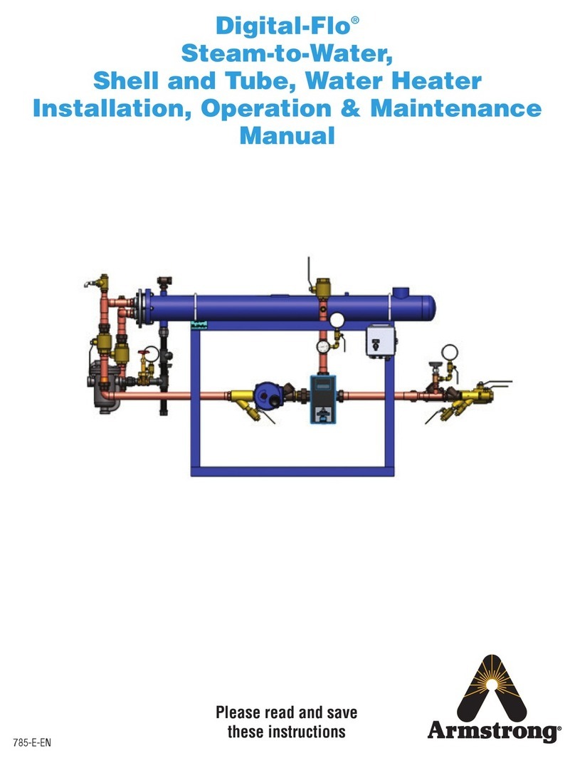
Since the DFSI design incorporates a steam-to-water, shell & tube type, heat exchanger, minimizing scaling and deposit
formation on heat exchange surfaces is critical to maintaining satisfactory operation. Therefore, consistent control of system
water quality could be a very important factor in maintaining the water heating performance of the DFSI Under certain
conditions (e.g., water with a high dissolved mineral content or high discharge water temperatures), scale build-up in the
heater and associated plumbing may be rapid & excessive causing heater performance to deteriorate to a noticeable level.
Periodic cleaning and descaling may be required under these conditions.
Where chloramine / chlorine disinfection is practiced, DO NOT exceed a chloramine / chlorine concentration of 50 mg/l (ppm)
in water, per one hour dwell time. Such procedures must be conducted strictly in accordance with the information supplied
with the disinfectant and with all relevant Guidelines/Approved Codes of Practice. Water must have levels of chloramine /
chlorine lower than or equal to 4 mg/l (ppm) for continual usage.
In any case, routine inspection & maintenance of the entire heater, especially the heat exchanger, the control valves, and other
wetted components, is highly encouraged to monitor normal wear and to detect and correct abnormal conditions that could
cause damage, system failure, and a subsequent hot water outage occur.
Only designated, qualified and competent personnel shall conduct product installation in
accordance with these instructions.
