7
10. Tomake thehighflowadjustment,SLOWLYincrease
the flow of water through the unit to drain while
monitoring the outlet thermometer. When the outlet
temperature has dropped by approximately 10 °F
below set point for a Model 415E, make your high
flowadjustmentwhilemaintainingthatflow.
11. Place a small screw driver or center punch through
the hole in the high flow adjustment stem (see Fig.
7-1)and turn itina clockwisedirection. Thiswill
start to close the valve restricting the cooling water
and cause the outlet water temperature of the unit to
rise. Continue until the outlet temperature is back up
to your required set point.
(IMPORTANT-Whenmakingthehighflow
adjustmentthelowflowadjustmentSHOULDNOT
rotatewiththehighflowadjustment.Ifitdoes,you
willhavetoholditstationarywhilemakingyour
highflowadjustment).
12. The unit is now adjusted.
(IMPORTANT-Ifforanyreasonyoumustreadjust
theunit,youwillfirsthavetoreturnthehighflow
adjustmentbacktoitsfulluppositionasstatedin
point#7).
START-UP AND ADJUSTING
PROCEDURE FOR MODEL 535EP,
665SEP and 8120
Follow all the steps 1-6 as stated in the adjustment
procedures of the model 415.
7. Locate the low flow temperature adjustment (LFT)
and the high flow temperature adjustment (HFT) on
top of the mixing valve hidden under the hex
bonnet (See Fig. 7-1). Before beginning
adjustments, check to make sure the LFT is fully
closed. To do this, turn the LFT clockwise until it
stops. Also make sure the HFT is fully open. To do
this start by pressing down on the HFT when water
pressure is present on the unit and there is no water
flow through the unit. The HFT should only depress
about 1/8". If it pushes in further, turn the HFT stem
counter clockwise to open. Check every turn until
there is only 1/8" travel to the HFT when pushed
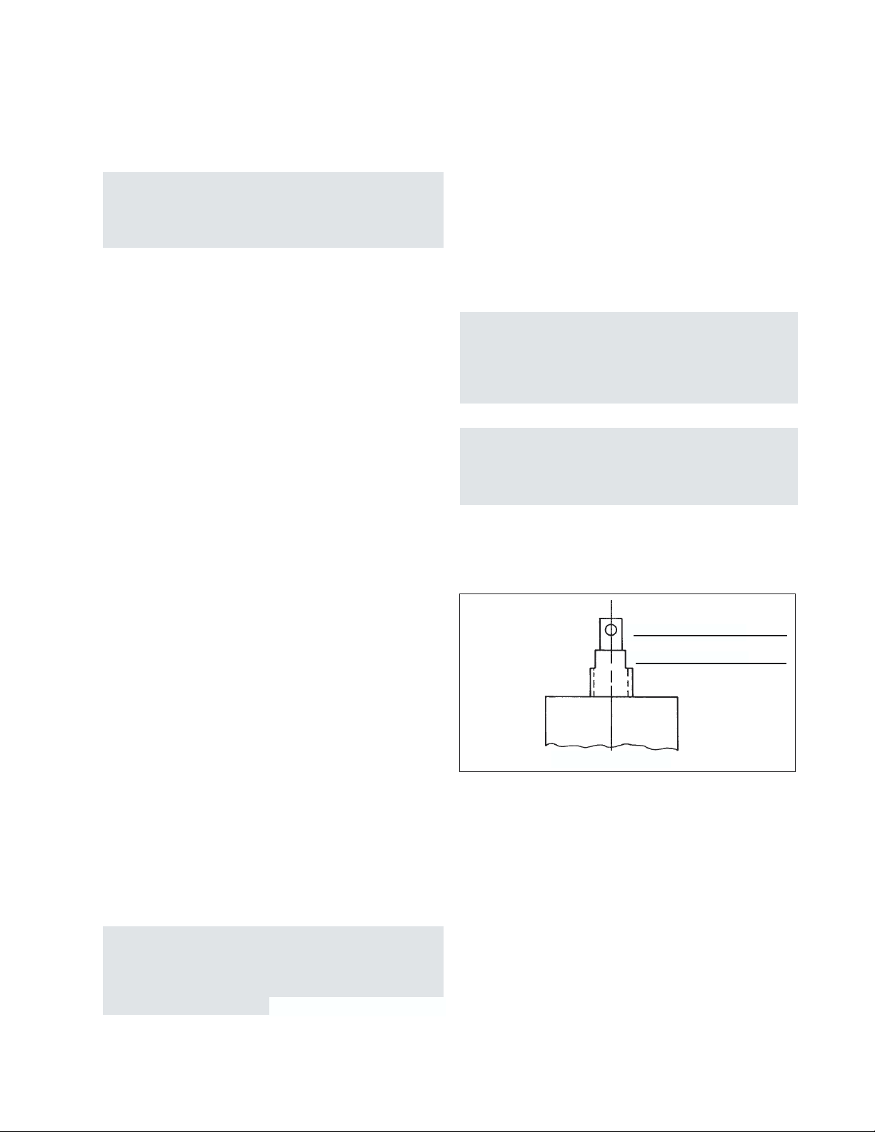
Figure 7-1
High Flow Adjustment (HFT)
Low Flow Adjustment (LFT)
Top Of Mixing Valve
!
!
4. Throttle the bypass valve to drain so that a constant
3 gpm of flow may pass to drain.
5. Slowly open steam valve or adjust the pressure
reducing valve to allow 2 - 15 psig of steam pressure
on the unit
(CAUTION:alwaysmakesurethereiswater
pressureontheunitbeforeaddingsteam.Failureto
dothiswillcauseseverehammeringoftheunitand
possibledamage).
6. Make sure that the steam trap draining the unit is
functioning properly and allow the entire unit to
come up to temperature for at least three to five
minutes while passing the 3 gpm of water flow to
drain before beginning the adjustment of the unit.
7. Locate the low and high flow adjustments on top of
the mixing valve hidden under the hex bonnet (see
Fig. 7-1). Before beginning adjustments, check to
make sure the high flow adjustment is fully open. To
do this start by pressing down on the high flow
adjustment when water pressure is present on the
unit and there is no water flow through the unit. This
should only depress about 1/8". If it pushes in
further, turn the adjustment stem counter clockwise
to open. Check every turn until there is only 1/8"
travel to the high flow stem when pushed down
(Note: with water pressure on the unit the stem
should pop back up after depressing it). If the high
flow adjustment stem will not depress at all the valve
is opened too far and you must turn the adjustment
clockwise until there is 1/8" travel downward to the
stem.
8. With the unit now isolated from the hot water system
and all flow of water being directed to drain at 3
gpm,letthe temperature stabilize.
9. Monitor the outlet temperature on the gauge located
in the bypass to drain (see Fig. 3-1B). Place an
adjustable wrench on the flats of the low flow
adjustment(seeFig.7-1).
Turning clockwise raises the discharge temperature
and counter-clockwise lowers the discharge
temperature. Make the appropriate adjustment to
achieve the desired set point. For example if a set
point of 140 °F is desired and the temperature reading
is 155 °F, you must turn the low flow adjustment
counter-clockwise to lower the set point temperature
from155°Fdownto140°F.
(IMPORTANT-Whenmakingthelowflow
adjustmentthehighflowadjustmentshaftSHOULD
rotatewiththelowflowadjustment.Ifitdoesnotdo
so,youwillhavetoturnitbyhandwhilemakingthe
lowflowadjustment). Allowtheunittostabilizeto
be sure that the unit will remain at the desired set
point. The low flow is now adjusted and should not
be readjusted.


 null")
 null")


 Operation and maintenance instructions")