manuals.online logo
Brands
  1. Home
  2. •
  3. Brands
  4. •
  5. ARNOLD
  6. •
  7. DC Drive
  8. •
  9. ARNOLD UA 500 User manual

ARNOLD UA 500 User manual

This manual suits for next models

1

Popular DC Drive manuals by other brands

National Instruments NI MID-7604 user guide

National Instruments

National Instruments NI MID-7604 user guide

SOMFY Maestria WT Series instructions

SOMFY

SOMFY Maestria WT Series instructions

Danfoss VLT HVAC Design guide

Danfoss

Danfoss VLT HVAC Design guide

Trane TR150 Service manual

Trane

Trane TR150 Service manual

Chamberlain Garog D Series operating manual

Chamberlain Garog

Chamberlain Garog D Series operating manual

Parker PDS Series user guide

Parker

Parker PDS Series user guide

Binks QS-5012-1-CE Service manual

Binks

Binks QS-5012-1-CE Service manual

Danfoss VLT 2800 Series Quick setup

Danfoss

Danfoss VLT 2800 Series Quick setup

YASKAWA CANopen SI-S3 Technical manual

YASKAWA

YASKAWA CANopen SI-S3 Technical manual

GE D20A6 instructions

GE

GE D20A6 instructions

Danfoss VLT AQUA Drive FC 202 operating manual

Danfoss

Danfoss VLT AQUA Drive FC 202 operating manual

Lenze PositionServo 940 user manual

Lenze

Lenze PositionServo 940 user manual

Unex MC-D-250-1000-050W-TW operating manual

Unex

Unex MC-D-250-1000-050W-TW operating manual

Geckodrive G213V manual

Geckodrive

Geckodrive G213V manual

ABB RSYC-01 user manual

ABB

ABB RSYC-01 user manual

Rockwell Automation PowerFlex 700S Programming manual

Rockwell Automation

Rockwell Automation PowerFlex 700S Programming manual

WEG DeviceNet CFW500 user manual

WEG

WEG DeviceNet CFW500 user manual

Siemens SINAMICS G List manual

Siemens

Siemens SINAMICS G List manual

manuals.online logo
manuals.online logoBrands
  • About & Mission
  • Contact us
  • Privacy Policy
  • Terms and Conditions

Copyright 2025 Manuals.Online. All Rights Reserved.

Page 1 of 11 12/2021 REV.19
_________________________________________________________________
OPERATING INSTRUCTIONS
UNIVERSAL DRIVE UA 500
1. General information
The universal drive UA 500 is approved for the safe rotation of heavy loads
(explicitly not persons) of up to 500 kg. One typical application is the drive of a
larger mirror ball or other objects. An integrated lamella torque clutch protects the
gear from overload and makes it possible to accelerate and decelerate large
masses without jolts. The drive is controlled manually or by a suitable DMX
Motor-Controller. The extremely robust design and the high-quality components
of the device guarantee a very high safety and longevity.
Page 2 of 11 12/2021 REV.19
2. Preparation / Assembly / Commissioning
Before each use, the motor shall be checked for possible damages. Special attention
shall be paid to the tight fit of the upper and lower eyebolt. The firm screwing of the
two halves of the housing is also important. These are secured by means of a bolt,
which is located under the guarantee label. A damage of the security seal can
indicate an inadmissible opening or loosening of the halves of the housing.
For fastening the drive on a load rod in theaters or on other structural components
and on the load to be driven, there are two eyebolts at both ends of the drive. For this
purpose, you can use permitted slings such as round slings, shackles or chain links
which can be screwed. A chain link which can be screwed (NG 12) with a nominal
load capacity or WLL (Working Load Limit) of 750 kg with regard to a working
coefficient of 10 is part of the scope of supply of the UA 500. Smaller fastening
elements can also be used in compliance with the dimensioning regulations
according to DGUV directive 17.
See also dimensioning according to DIN 56950-1 “Entertainment Technology –
Machinery Installations – Part 1: Safety requirements and testing". The drive itself is
designed for a breaking load of more than 15 t and has demonstrably the 10-fold
safety required according to DGUV directive 17.
Please avoid greater asymmetrical load distributions! Otherwise too high lateral and
tensile forces can occur at the fastening elements!
The motor is only designed for a vertical load. After fastening and securing the drive,
the connection to the Motor-Controller is established. In order to avoid a danger due
to uncontrolled movements, the connection to the power supply may only be
established thereafter. Please observe that objects with large dimensions or surfaces
have considerable air resistances and already trigger the torque clutch of the UA 500
at low rotation speeds.
The kinetics of a large object can also cause very long acceleration and deceleration
phases. In case of doubt please contact us. We will be pleased to advise you with
regard to your planned application.
Page 3 of 11 12/2021 REV.19
3. Safety instructions
Please observe the instructions for the permitted installation position and load limits
of the UA 500. For the protection of the gear unit and due to reasons of the safety at
work (prevention of the risk of crushing), a torque clutch with a nominal torque of 1.3
Nm is integrated, which allows a soft acceleration and deceleration of corresponding
heavy loads. The UA 500 has different safety features, which are reviewed prior to
delivery. In order to ensure a high operating safety, the halves of the housing are
sealed and must never be opened. Both eyebolts M 16 are secured with a specific
locking agent because of safety reasons and may neither be loosened nor replaced
by other components. We are not liable for damages resulting from non-observance.
Therefore, we reject any liability in this respect.
The drive automatically restarts as soon as the operating voltage returns after a
mains power failure. Please consider possible resulting risks.
The device may only be used for driving decorating elements and objects on stages
and for similar tasks. It is not permitted to turn or move persons with the UA 500.
Only qualified persons may attach and start the drive (event or stage technicians or
similar specialists).
It must be ensured that the attachment points and slings also correspond to the high
requirements of the DGUV directive 17! In addition, we refer to the regulations
according to EN ISO 13855 "The positioning of protective equipment with regard to
the approach speed of parts of the human body" and EN ISO 13857 "Safety
distances to prevent danger zones being reached by upper and lower limbs" and DIN
EN 349 "Minimum distances to avoid crushing parts of the human body“
Due to the high intrinsic safety of the drive, a second protection of the drive itself is
not necessary. However, it is particularly important to pay attention to an absolutely
safe fastening of the drive at the bearing elements. For the suspension of a mirror
ball, particular attention must be paid to a safe fastening of its axis.
Page 4 of 11 12/2021 REV.19
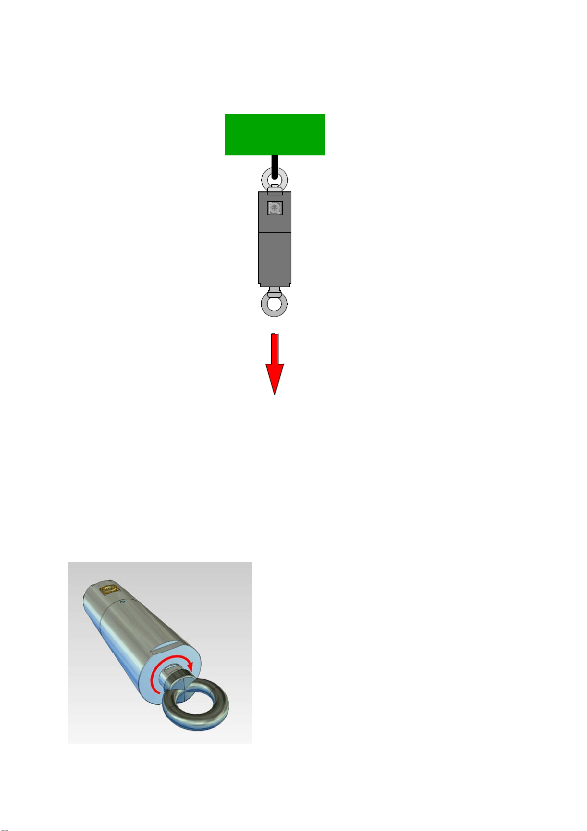
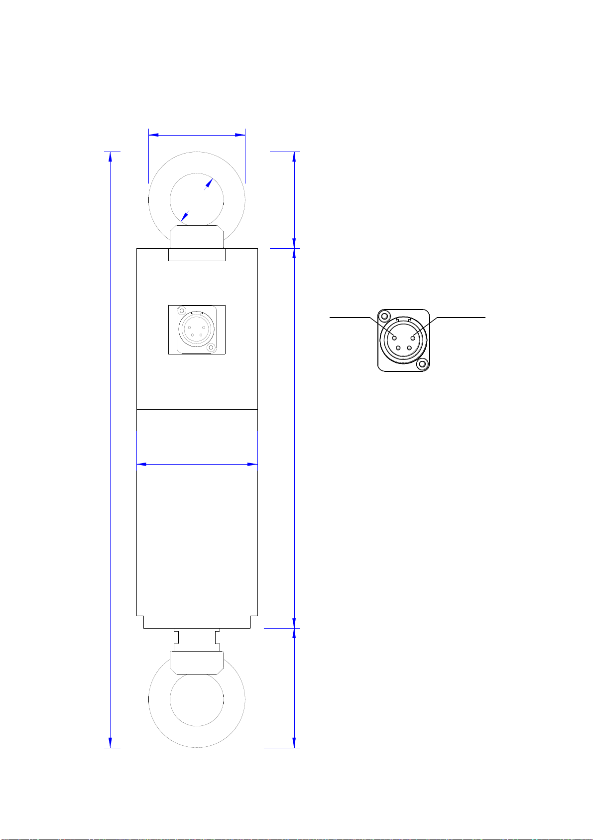
Possible existing additional safety fastenings of the mirror ball or other objects can be
connected with the lower eyebolt. In order to limit the dynamic load of the drive and
the attachment point at the mirror ball, the drop height must be restricted by a
corresponding calculation of the safety wire to less than 20 cm. The use of a safety
wire with a fall brake of the type “Major Saveking” is recommended.
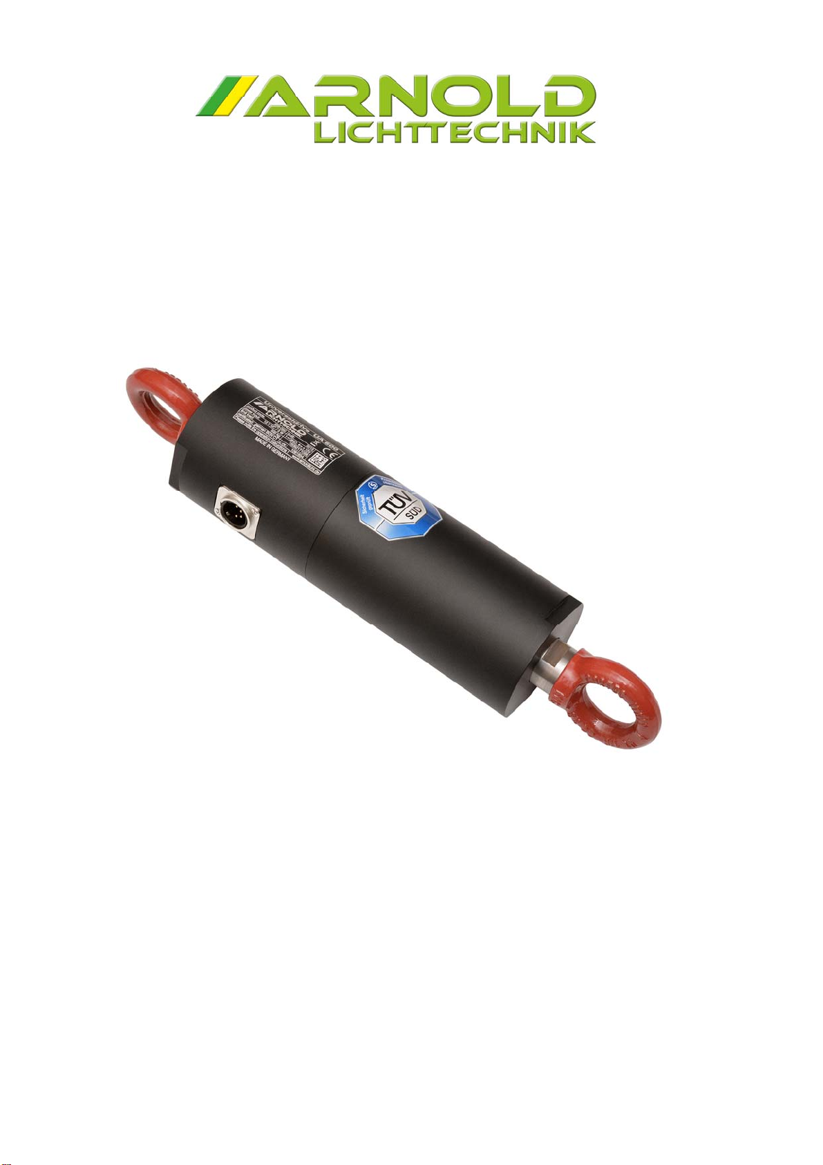
The universal drive UA 500 is a product designed for the application on stages, which
is designed corresponding to the state-of-the-art in a way that risks can be largely
excluded. Nevertheless, drives and drive controls, which do not explicitly fulfill safety
functions, are, according to the general technical view, not permitted for applications
which may endanger persons due to the drive function. Unexpected or non-braked
movements can never be completely excluded without additional safety devices.
Therefore, persons must never stay in the danger zone of the drives, unless
additional adequate protective equipment excludes any danger to persons. This
applies both for the regular operation of the machine as for all maintenance and
commissioning works. In order to avoid personal injuries and damages to property,
adequate precautions shall be taken, if necessary.
The turning range of the driven element must not be entered by persons and / or
must be outside the hand area.
The commissioning, operation and maintenance may only be performed by trained
event technicians. These specialists must know and be familiar with the content of all
technical documentations of this product. Due to their technical training, knowledges
and experiences, these specialists must be able to recognize and avoid dangers.
The specialists must know the common standards, provisions and accident
prevention regulations, which must be complied with during installation, operation
and maintenance of the product. Damaged drives may neither be installed nor
commissioned in order to prevent personal injuries and damages to property.
Changes and modifications of the drives are not permitted and will result in the
voiding of all warranties and liabilities. Please observe that the drive may only be
operated in dry rooms (IP 40).
Page 5 of 11 12/2021 REV.19
4. Inspection intervals
In order to guarantee a permanently high operating safety, a brief inspection shall be
performed prior to each application (see point 2).
The complete drive is a safety relevant component and must, thus, be annually
inspected by a correspondingly trained expert according to the safety-at-work
directive (German directive: BetrSichV 2002) and DGUV directive 17.
This inspection must include the following points:
1. Check for possible damages of the housing
2. Check the eyebolts for damages and tight fit
3. Check the secure connection between upper and lower part. In this
process, particular attention must be paid to possible damages of the
security seal.
4. Check the slings (shackle / chain link and the like)
5. Check the cables, power supply units and plug-in connectors.
An inspection by an expert (e.g. TÜV) is required every 4 years. This inspection may
be carried out by the locally competent TÜV organization.
For the documentation of these cyclic inspections, an inspection book is attached to
every motor. Please consider that you put lives at risk with a defective drive. The
costs of an inspection are low compared to this danger! Please send the drive to the
company ARNOLD Lichttechnik for a more thorough inspection, if there are visible
damages that suggest a limitation of the operating safety (e.g. after a crash of the
drive).
Page 6 of 11 12/2021 REV.19
5. Permitted installation position
The universal drive UA 500 is exclusively approved for the hanging / vertical
operating mode displayed in the graphics. Off-center loads or the standing operation
are not permitted.
6. Direction of rotation
The UA 500 is driven by a direct current gear
motor and can, thus, be easily controlled in its
direction of rotation and its speed. The two
offered control units provide this function via
DMX or manually by means of a switch. The
“clockwise rotation” of the drive is shown below.
Clockwise rotation of the drive
500 K
g
Page 7 of 11 12/2021 REV.19
7. Technical data
Load capacity: up to 500 kg hanging (only axially)
Rotation speed: 0.3 – 3.0 rpm
Torque: max. 1.3 Nm
Drive: precision planetary gear motor
Operating voltage: 12 V DC / 200 mA
Housing: hard aluminum, black anodized
Plug connection: XLR jack 4- pin male
Cable length: 2 m (scope of supply)
Total weight: 3.2 kg
Protection class: IP 40 (dry rooms)
Security: requirements of the DGUV directive 17
Certification: conformity checked according to Machinery
Directive 2006/42/EC by TÜV SÜD
8. Scope of supply / order numbers:
Universal drive type UA 500, load capacity 500 kg 559-050
Transport case for UA 500 503-151
Connection cable motor towards controller XLR 4-pin / 2m 503-155
Quick connecting link NG 12 WLL 750 kg 503-154
Motor-Controller (optional)
Original operating instructions and inspection book UA 500
Transport case Chain quick connector NG 12
Page 8 of 11 12/2021 REV.19
For the operation of the UA 500 the following are (optionally) required:
Motor-Controller MCU 910 mini (manual) 536-050
(
speed adjustable via potentiometer, direction of rotation
manually switchable incl. wall wart)
or
Motor-Controller MCU 400 D (DMX + manual) 515-060
(
direction of rotation and speed
controllable manual and via DMX)
Page 9 of 11 12/2021 REV.19
9. Wiring examples
Motor control with Motor-Controller MCU 910 mini (manual control)
Motor control with Motor-Controller MCU 400 D (DMX + manual)
DMX Control
XLX 5-pin
Power Supply 2 x 0,37mm²
max. 20m
MCU 400 D UA 500
12V DC
XLR 4-pin
12V DC/ 2A
XLR 3-pin
UA 1500
UA 500
MCU 910 mini
12V DC
12V DC
XLR 3-pin
XLR 4-pin
2 x 0,37mm²
max. 20m
Power Supply
12V DC/ 2A
IN
P
U
T
S
PE
ED
L
R
MOTOR
UA 1500
Page 10 of 11 12/2021 REV.19
10. Dimensions
389.00
Connector XLR 4 (male)
248.00
78.00
ø79.00
3
2
41
0V ( GND ) + 12 V DC
ø35.00
63.00
ø63.00