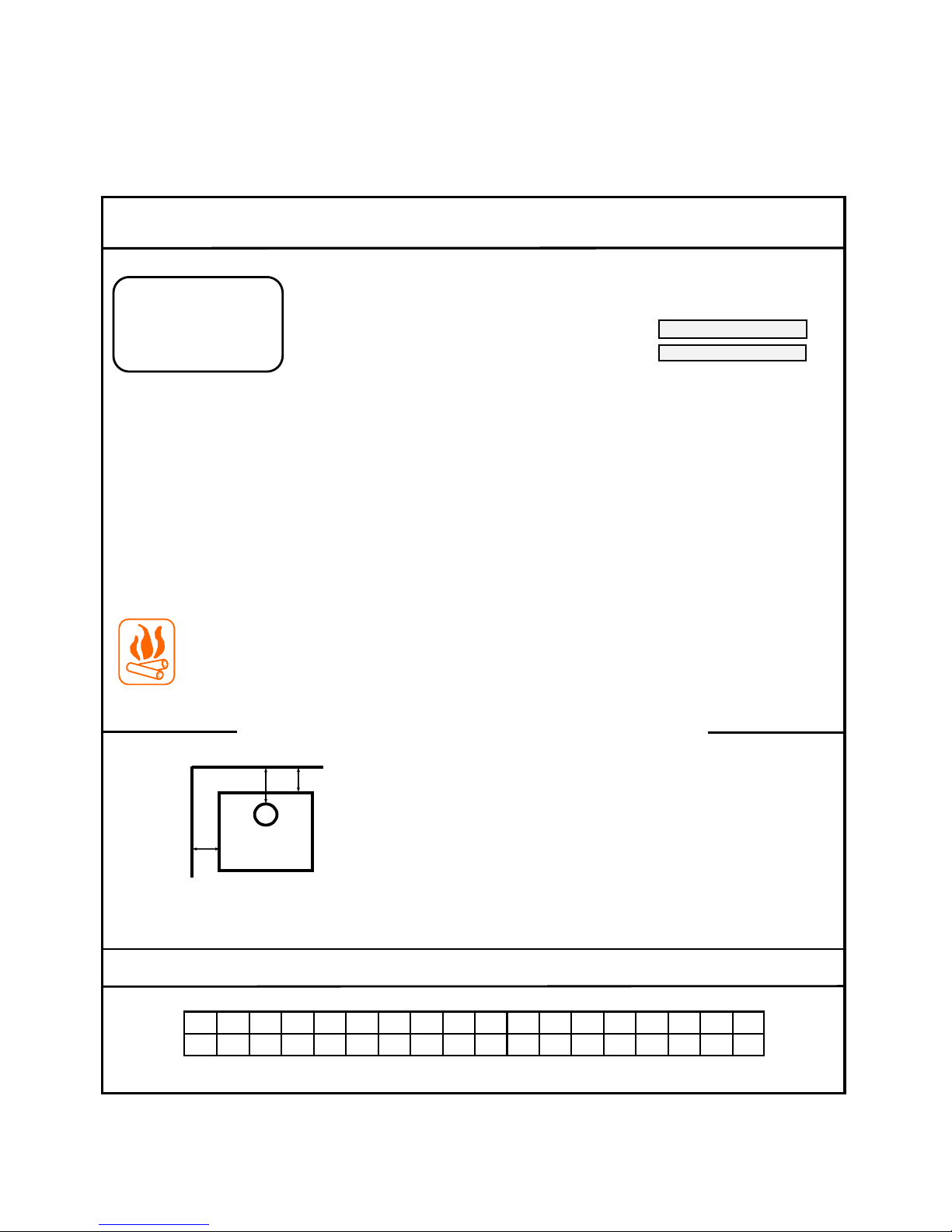
DATA LABEL PLATE
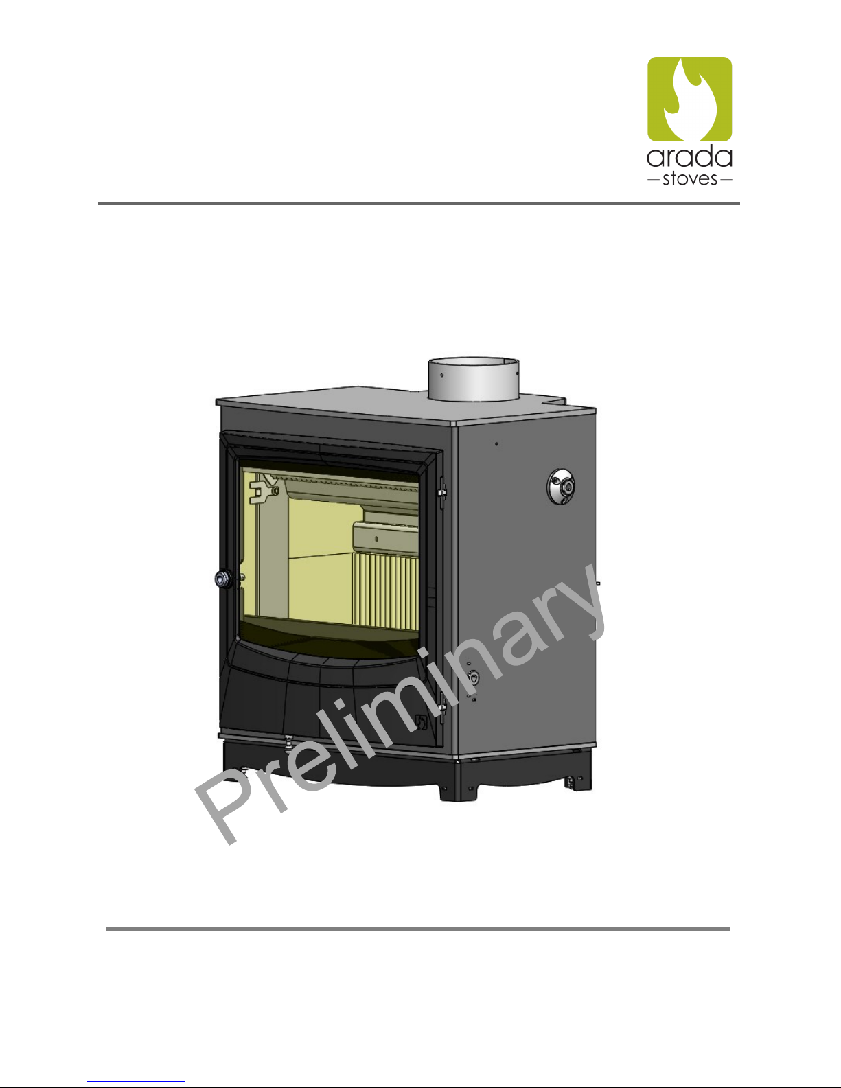
Arada Farringdon Stoves
8
Farringdon 16 Safety Label
WARNINGS - ATTENTION
Do NOT burn with the grate system removed
Ne pas utiliser sans la grille
Do NOT overfire, If the chimney connector glows you are overfiring. (See Manual)
Ne pas surchauffer. Si le collet de la cheminee devient rouge. Le poele sur-
chauffe (Voir notice d’utilisation)
Do NOT obstruct the space under the heater
Ne Rien entreposer sous le poele
Do NOT connect this unit to a chimney serving another appliance
Ne pas brancher cet appareil sur une cheminee servant a un autre appareil
This stove is only to be operated with the door CLOSED
Le poele doit etre utilise porte FERMEE
Use solid wood fuel ONLY
Pour une utilisation avec du bois de chauffage SEULEMENT
CONTACT YOUR LOCAL BUILDING OFFICIAL ABOUT RESTRICTIONS AND INSTALLATION INSPECTION IN YOUR AREA
CONTACTER VOTRE RESPONSABLE D’INSTALLATION LOCAL POUR CONNAITRE LES RESTRICTIONS ET INSPECTIONS DES INSTALLATIONS
DANS VOTRE REGION
Listed Room Heater. Wood Fuel type, Poele a bois homologue
Test house logo and info
TBA
Not suitable for use in a Mobile Home
Ne pas utiliser dans les maisons
mobiles
Manufactured by, Fabrique par Arada Ltd
Axminster, Devon
United Kingdom EX13 5HU
Serial #, No. de serie
Model Name, Modele
Tested To, Mis a l’epreuve selon la norme:-
UL1482-11, ULC S627-00
* PREVENT HOUSE FIRES* * EVITER LES INCENDIES*
DO NOT REMOVE THIS LABEL, NE PAS RETIRER CETTE PLAQUE SIGNALETIQUE
Date of Manufacture, Date de Fabrication
2015 2016 2017 2018 2019 2020 Jan Feb Mar Apr May Jun Jul Aug Sept Oct Nov Dec
U.S. ENVIROMENTAL PROTECTION AGENCY
Certified to comply with xxx, 2015 particulate emissions standards
Minimum Clearance to Combustible Materials*, Degagement minimum aux materiaux combustibles*
BACKWALL, MUR DU FOND
SIDEWALL, MUR DE COTE
B
C
A = 18” / 456mm
B = 12” / 305mm
C = 16” / 400mm
Made in England, Fabrique en Angleterre
Farringdon 16
xxxxxxxxxxxx
When installed on a combustible floor, Non-combustible
floor protection is required to cover the area beneath
the stove, and extend at least 18” (458mm) to the front
and 8” (203mm) to the sides and back.
Si le poele est installe sur un sol combustible, alors un
protege plancher incombustible doit etre utilise pour
couvrir la surface sous le poele et doit s’etendre au
moins 18” (458mm) a l’avant et 8” (203mm) sur les cotes
et a l’arriere.
* Refer to the Installation manual for additional
clearance information, Installation instructions
and Operating instructions.
Se referrer a la notice d’ utilisation pour des
informations complementaires sur les degaga-
ments, les instructions pour l’installation et
l’utilisation.
Install and use only in accordance with manufacturers installation
instructions and your local building codes
Installer et utiliser seulement conformement aux instructions du
fabricant et aux normes d’installation dans votre region
Caution: Special methods are required when passing chimney
through a wall or ceiling, refer to local building codes. Do not connect
this stove to a chimney serving another appliance.
Attention: Des procedes speciaux doivent etre employes pour
passer un conduit de cheminee au travers de murs ou de plafonds.
Referez-vous aux normes d’installation de votre region. Ne pas
brancher cet appareil sur une cheminee servant a un autre appareil.
Note: Replace glass only with 5mm minimum Ceramic IR or
Neoceram IR glass
Remarque: Remplacer la vitre seulement avec un verre Ceramic
IR ou Neoceram IR de 5mm d’epaisseur
Warning: This unit is not suitable for use in a Mobile Home
Attention: Ne pas utiliser dans les maisons mobiles
Inspect and clean the chimney frequently.
Under certain conditions of use, creosote buildup can occur
RAPIDLY.
Inspecter et nettoyer la cheminee regulierement. Dans certaines
conditions d’utilisation , la creosote peut s’accumuler rapidement
The Stove data label is manufactured from plated mild steel, laser etched with the information detailed below.
and is permanently fixed to the top of the stove heat shield
Caution - Attention:
The stove is very hot during operation. Do Not Touch, Keep children,
clothing and furniture away. Contact with skin burns. See nameplate
and Instructions.
Le poele est tres chaud pendant l’utilisation. Ne pas toucher, garder
les enfants, tissus et meubles a distance. Le contact avec la peau
cause brulures. Voir la plaque signaletique et les instructions.
AGENCE U.S. POUR LA PROTECTION DE L’ENVIRONNEMENT
Certifie conforme a xxx, norme d’ emission de particules
VENT REQUIREMENTS:
6” (150mm) diameter, single wall,
Minimum 24 MSG blue steel connector with
Listed factory-built Type HT chimney or
masonry chimney.
CARACTERISTIQUES POUR LES CONDUITS
Raccord en acier bleu minimum 24MSG de
6” (150mm) paroi simple, avec une cheminee en
acier fabrique en usine homologue de type HT ou
une cheminee de maconnerie.
A