Arregui CI10 User manual

CI10
ES Cerradura de seguridad invisible para puertas, con
mando a distancia.
IT Serratura di sicurezza invisibile per porte, con
telecomando.
PT Ferrolho de segurança invisível para portas, com
comando à distancia.
EN Invisible safety lock for doors, with remote control.
FR Verrou de sécurité invisible pour portes, avec
télécommande.
DE Unsichtbares Sicherheitsschloss für Türen, mit
Fernbedienung.
arregui.es I arregui.it I arregui.biz I arregui.fr

COMPONENTES / COMPONENTI / COMPONENTES / COMPONENTS / COMPOSANTS / BESTANDTEILE
ES Bulones
IT Bulloni
PT Trancas
EN Bolts
FR Pênes
DE Bolzen
ES Antena
IT Antenna
PT Antena
EN Antenna
FR Antenne
DE Antenne
ES Tapa de alojamiento de pilas
IT Coperchio del vano batteria
PT Tampa de alojamento das pilhas
EN Battery storage cover
FR Couvercle compartiment à piles
DE Batteriefachabdeckung
ES Tornillo de alojamiento de pilas
IT Vite del vano batteria
PT Parafuso de alojamento das pilhas
EN Battery storage screw
FR Vis du compartiment à piles
DE Batteriefachschraube
ES Pomo de apertura manual
IT Manopola per apertura manuale
PT Puxador de abertura manual
EN Manual opening knob
FR Bouton d’ouverture manuel
DE Manueller Öffnungshenkel
CI10

D
A
B
C
E OE1JP
F
K
L
M
N
GH
I
CI10


5
SE RECOMIENDA REALIZAR LA CONFIGURACIÓN DE LOS MANDOS ANTES
DE LA INSTALACIÓN DE LA CERRADURA EN LA PUERTA.
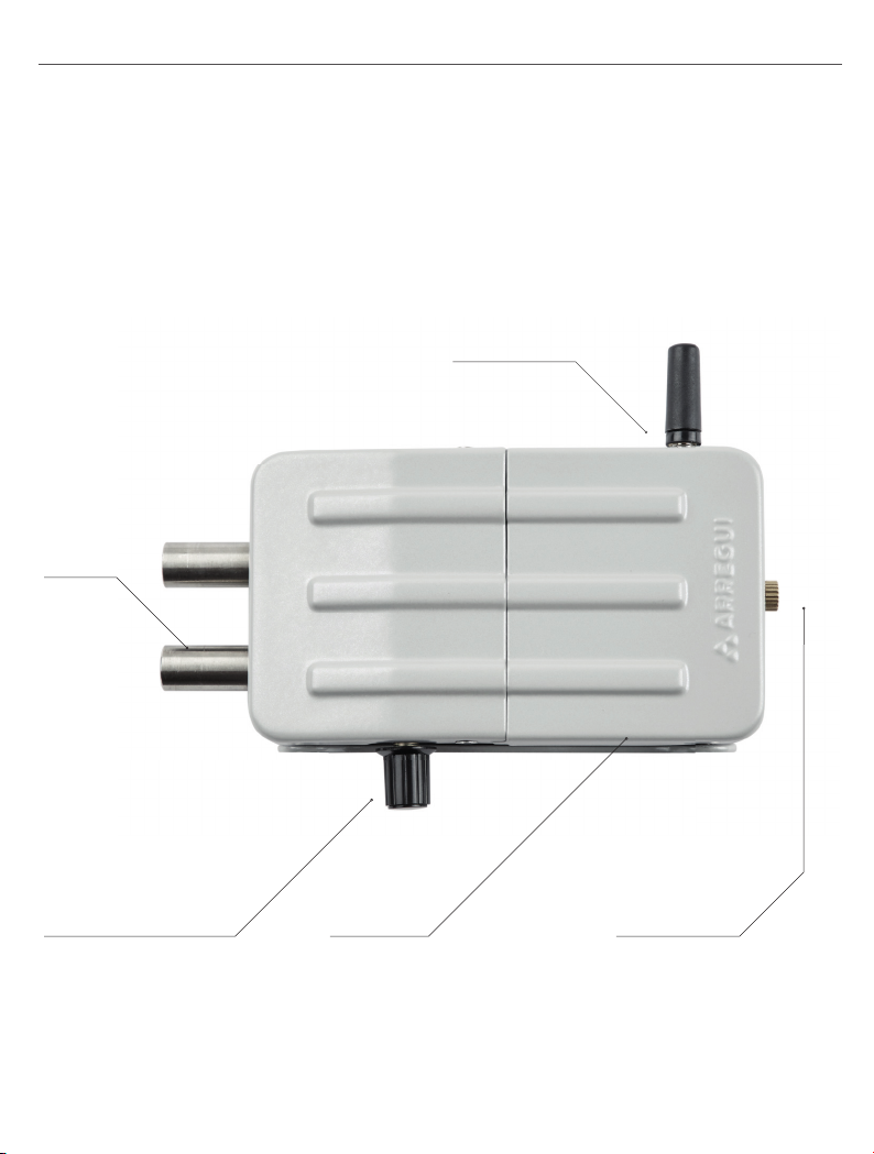
COLOQUE LA ANTENA Y LAS PILAS DE LA CERRADURA:
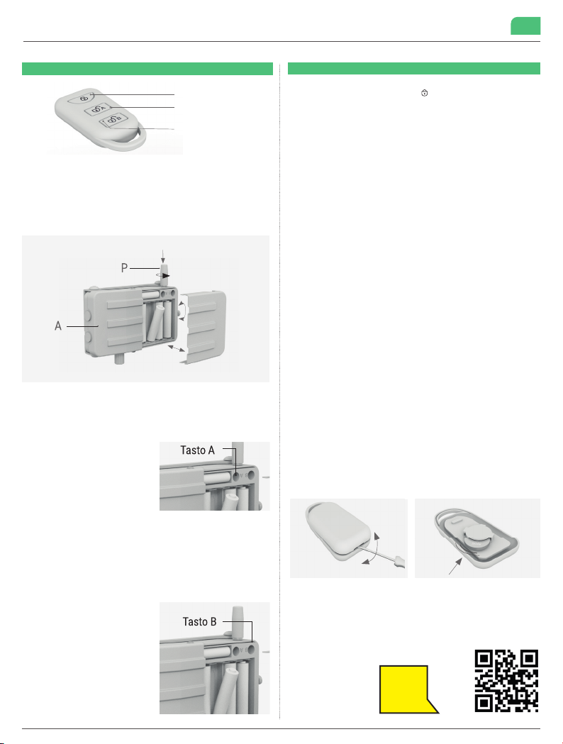
• Coloque la antena (P). Quite la tapa del cuerpo de la cerradura (A) desatorni-
llando el tornillo dorado del lateral. Introduzca las pilas J (4 x AA) y la batería
de emergencia K (12V).
CONFIGURACIÓN DE LOS MANDOS A DISTANCIA PARA APERTURA DE LA
CERRADURA:
•Tirar del plástico protector de la batería, para activar los mandos.
• Coloque los mandos cerca de la cerra-
dura.
• Paso 1: Con ayuda de la llave allen (N),
presione 2 veces seguidas el botón de
registro A de la cerradura, mantenien-
do presionado el botón la segunda vez
hasta que confi gure los mandos (so-
nará un pitido cada vez que presione el
botón).
• Paso 2: Pulse el botón A de cada mando que quiera enlazar a la cerradura,
presionándolo una vez (sonarán dos pitidos cuando se haya enlazado).
En el paso 2 puede confi gurar todos los mandos si presiona el botón A de
cada uno de ellos de manera rápida y consecutiva. Recuerde que debe man-
tener presionado el botón A de la cerradura durante todo el proceso.
En caso que deje transcurrir cierto tiempo entre un mando y otro, deberá vol-
ver a repetir el paso 1 antes de confi gurar cada mando.
• Compruebe que todos los mandos
funcionan, abriendo y cerrando la ce-
rradura.
CONFIGURACIÓN DE LOS MANDOS
A DISTANCIA PARA APERTURA DE
EMERGENCIA:
Realizar el mismo proceso indicado en
el apartado anterior, pero presionando
el botón de registro B de la cerradura
y pulsando el botón B de los mandos a
distancia.
CIERRE
Para cerrar la cerradura pulse el botón ( ) del mando a distancia. Una vez cerra-
do se escuchará 1 pitido.
IMPORTANTE: cuando las pilas se estén agotando, la cerradura emitirá 4 pitidos
y no se realizará el cierre.
APERTURA NORMAL
Para abrir la cerradura pulse el botón A del mando a distancia. Una vez abierto se
escucharán 2 pitidos.
IMPORTANTE: cuando las pilas se estén agotando, sonarán 5 pitidos al abrir la
cerradura. Debe cambiar las pilas para garantizar un funcionamiento correcto.
APERTURA DE EMERGENCIA:
En caso de que la cerradura no funcione al pulsar el botón A del mando a distancia
(por pilas agotadas), debe realizarse una apertura de emergencia. Hay que activar
la pila golpeando la puerta repetidamente (como si se estuviera llamando) ya que
la pila de emergencia permanece inactiva para evitar su consumo.
Se escuchará un pitido y 2 segundos después debe presionar el botón B del man-
do a distancia. La cerradura se abrirá.
APERTURA MANUAL O USO DE LA CERRADURA COMO PESTILLO:
Puede bloquear y desbloquear los bulones girando el pomo de apertura manual
en el sentido contrario a las agujas del reloj.
IMPORTANTE: EN CASO DE EXTRAVÍO DE MANDO A DISTANCIA
Por seguridad, en caso de pérdida de algún mando a distancia, se deben descon-
fi gurar todos los mandos y volver a repetir el proceso de confi guración, ya que de
esta manera se modifi ca el código de apertura y evita que el mando extraviado
pueda abrir la cerradura invisible.
PARA DESCONFIGURAR LOS MANDOS A DISTANCIA:
Para borrar los códigos de apertura A de los mandos, presionar de manera conti-
nua el botón de registro A de la cerradura (10 segundos aproximadamente) hasta
que suene un pitido largo.
Para borrar los códigos de apertura B de los mandos, presionar de manera conti-
nua el botón de registro B de la cerradura (10 segundos aproximadamente) hasta
que suene un pitido largo.
CAMBIO DE PILAS
• Cuando las pilas de la cerradura se estén agotando se emitirán señales sonoras
(ver indicaciones en “Cierre” y “Apertura”). ES IMPORTANTE CAMBIAR LAS PILAS
1 VEZ AL AÑO, PARA GARANTIZAR EL FUNCIONAMIENTO DEL PRODUCTO.
CÓMO CAMBIAR LA PILA DEL MANDO A DISTANCIA ( 1 X CR2032 3V )
RECOMENDACIONES
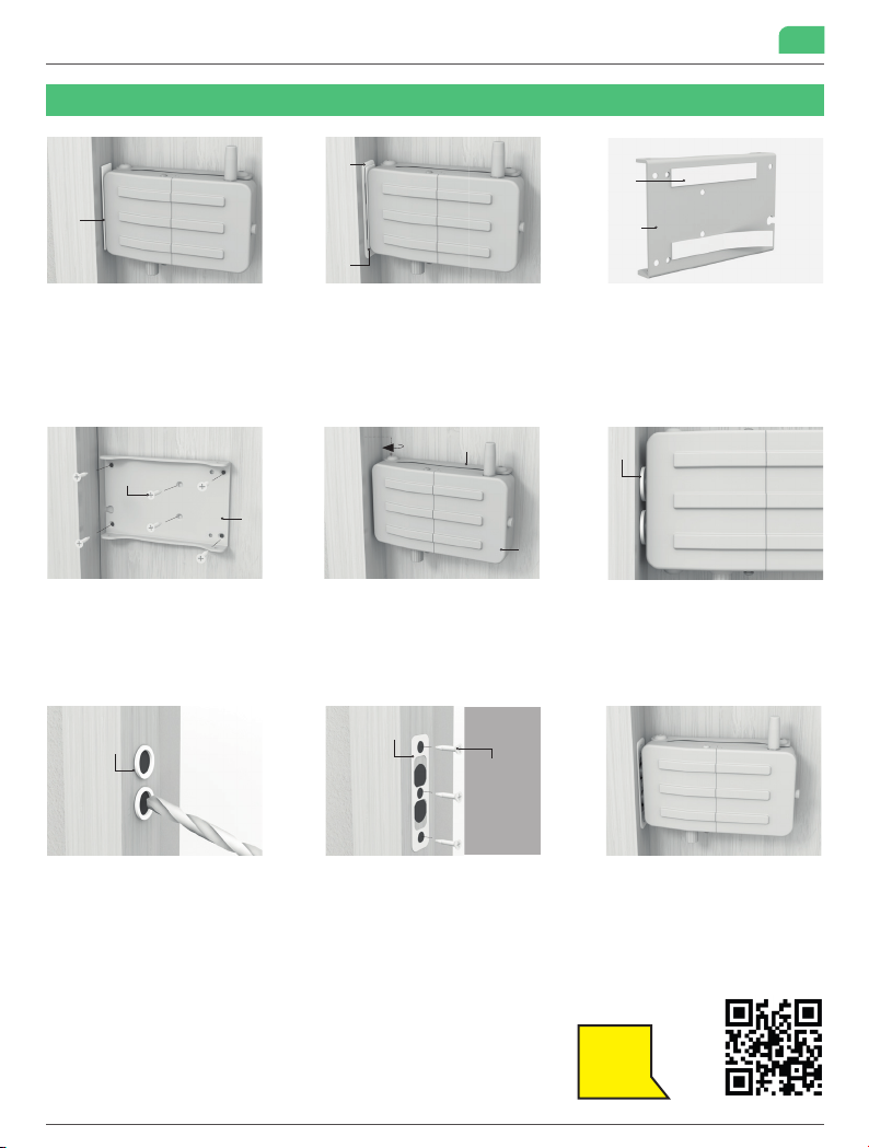
• Se recomienda medir la altura a la que se ha instalado la cerradura invisible, por
si el servicio técnico tiene que realizar una intervención de emergencia. Mida la
distancia desde el suelo hasta la parte inferior de la cerradura y memorícela (otras
opciones: anotarla en la agenda del teléfono móvil, comunicarla a una persona de
confi anza, …).
INSTRUCCIONES PUESTA EN MARCHA INSTRUCCIONES DE USO
Cerrar
(A) Apertura cerradura
(B) Apertura emergencia
Véalo
en vídeo
CI10 Es

6
7. Repita el proceso de taladrar para sujetar el
alojamiento de bulones (E) a la puerta, mediante
los tornillos suministrados (M)
M
E
8. Coloque a presión el embellecedor (E1)
Importante: Verifi que el
correcto funcionamiento de
la cerradura, siempre desde el
interior de su casa.
E1
1. Calcule en qué posición quiere instalar la
cerradura, siempre por el interior de la puerta.
Coloque el distanciador adhesivo (H) según
muestra la imagen, pegado al cuerpo del cerrojo.
H
2. Al lado del distanciador adhesivo (H)coloque
el alojamiento de bulones (E) sobre el marco de
la puerta. El distanciador le marca la separación
mínima entre la cerradura y el alojamiento de
bulones. Si ambos no están a la misma altura,
deberá utilizar las piezas (C) y (D) para calzar la
cerradura en el paso 4.
E
3. Fije las bandas adhesivas (I) en la trasera
de la placa base (B) o en las calzas (C y D),
para posicionarla adecuadamente sobre la
puerta antes de taladrar.
I
B
A
4. Una vez pre-colocada la placa base (B) y las
calzas (C) y (D) si fueran necesarias, se taladra
y se sujeta a la puerta mediante los tornillos
suministrados (M).
5. Atornille el cuerpo de la cerradura (A) a la
placa base (B), mediante los 4 tornillos (L)
suministrados.
LB
6_A. Para un mejor ajuste de los bulones, la pie-
za E puede instalarse en 2 posiciones distintas.
Con los bulones en posición cerrado verifi que en
qué posición instalarla. Los bulones deben que-
dar lo más cerca posible del borde de la pieza E
para evitar holgura al abrir la puerta.
6_B. Coloque la pieza de alojamiento de bulones
(E) en el marco de la puerta, sujetándola con una
banda adhesiva (I), a la altura adecuada para que
los cerrojos se puedan cerrar y bloqueen la puerta.
E
I
A
M
B
Véalo
en vídeo
INSTRUCCIONES DE MONTAJE DE SUPERFICIE
E
CI10 Es

7
3. Fije las bandas adhesivas (I) en
la trasera de la placa base (B) o en
las calzas (C y D), para posicionarla
adecuadamente sobre la puerta antes
de taladrar.
I
B
1. Calcule en qué posición quiere instalar
la cerradura, siempre por el interior de la
puerta. Coloque el distanciador adhesivo
(H) según muestra la imagen, pegado al
cuerpo de la cerradura.
H
H
F
2. Al lado del distanciador adhesivo ( H)
coloque el embellecedor (F) sobre el marco
de la puerta. El distanciador le marca la
separación mínima entre la cerradura y
el embellecedor. Si ambos no están a la
misma altura, deberá utilizar las piezas (C) y
(D) para calzar la cerradura en el paso 4.
6. Retire el distanciador adhesivo.
Coloque los discos adhesivos (G) en los
bulones de la cerradura.
G
4. Una vez pre-colocada la placa base (B)
y las calzas C y D si fueran necesarias, se
taladra y se sujeta a la puerta mediante
los tornillos suministrados (M).
5. Atornille el cuerpo de la cerradura (A) a la
placa base (B), mediante los 4 tornillos (L)
suministrados.
L
A
B
7. Extienda los bulones y los discos adhe-
sivos quedarán pegados en el marco de la
puerta.Taladre los agujeros centrales del
disco pegado en el marco, con herramien-
tas adecuadas según el material.
Utilice el disco (G) como plantilla para
perforar los agujeros. No sobrepase nunca
las dimensiones de la plantilla.
G
8. Coloque el embellecedor (F) fi jándolo
con los tornillos (M) sobre el marco de
la puerta.
F
M
Importante: Verifi que el correcto funcio-
namiento de la cerradura, siempre desde el
interior de su casa.
INSTRUCCIONES DE MONTAJE PARA EMBUTIR
M
B
Véalo
en vídeo
CI10 Es

8
CI10 It
SI CONSIGLIA DI EFFETTUARE LA CONFIGURAZIONE DEI TELECOMANDI
PRIMA DI INSTALLARE LA SERRATURA SULLA PORTA.
POSIZIONARE L’ANTENNA E LE BATTERIE DELLA SERRATURA:
• Posizionare l’antenna (P). Rimuovere il coperchio del corpo della serratura
(A) svitando la vite dorata sul lato. Inserire le pile J (4 x AA) e la batteria di
emergenza K (12V).
CONFIGURAZIONE DEI TELECOMANDI PER L’APERTURA DELLA
SERRATURA:
• Sollevare la plastica protettiva della batteria per attivare i telecomandi.
• Posizionare i telecomandi vicino alla serratura.
• Fase 1: Con l’aiuto della chiave a bru-
gola (N), premere due volte di seguito il
tasto di registrazione A della serratu-
ra, tenendo premuto il tasto la seconda
volta fi no a quando non si confi gurano i
telecomandi (ad ogni pressione del tas-
to viene emesso un segnale acustico).
• Fase 2: Premere il tasto A di ogni telecomando che si desidera collegare
alla serratura, premendolo una volta (verranno emessi due segnali acustici
quando sarà collegato).
Nella fase 2 è possibile confi gurare tutti i telecomandi premendo il tasto A di
ciascuno di essi in modo rapido e consecutivo. Ricordarsi di tenere premuto
il tasto A della serratura per tutta la durata del processo.
Se si lascia trascorrere un certo tempo tra un telecomando e l’altro, è necessa-
rio ripetere la fase 1 prima di confi gurare ogni telecomando.
• Verifi care che tutti i telecomandi fun-
zionino aprendo e chiudendo la serra-
tura.
CONFIGURAZIONE DEI TELECOMANDI
PER L’APERTURA D’EMERGENZA:
Eseguire la stessa procedura descritta
nella sezione precedente, ma premendo
il tasto di registrazione B della serra-
tura e premendo il tasto B dei teleco-
mandi.
CHIUSURA
Per chiudere la serratura, premere il tasto ( ) sul telecomando. Una volta chiusa,
si sentirà 1 bip.
IMPORTANTE: quando le batterie sono scariche, la serratura emette 4 segnali
acustici e la serratura non si chiude.
APERTURA NORMALE
Per aprire la serratura, premere il tasto A del telecomando. Una volta aperta, si
sentiranno 2 bip.
IMPORTANTE: quando le batterie sono scariche, la serratura emette 5 segnali
acustici al momento di essere aperta. Le batterie devono essere sostituite per
garantire il corretto funzionamento.
APERTURA DI EMERGENZA:
Se la serratura non funziona premendo il tasto A del telecomando (batteria scari-
ca), deve essere effettuata un’apertura di emergenza. La batteria deve essere atti-
vata colpendo ripetutamente la porta (come se si stesse effettuando una bussata)
in quanto la batteria di emergenza rimane inattiva per evitare il consumo.
Si sentirà un bip e dopo 2 secondi si deve premere il tasto B del telecomando. La
serratura si aprirà.
APERTURA MANUALE O UTILIZZO DELLA SERRATURA COME CHIAVISTELLO:
È possibile bloccare e sbloccare i bulloni ruotando la manopola di apertura
manuale in senso antiorario.
IMPORTANTE: IN CASO DI SMARRIMENTO DEL TELECOMANDO
Per motivi di sicurezza, in caso di perdita di un telecomando, tutti i telecomandi
devono essere disattivati e si deve ripetere l’operazione di confi gurazione, in quan-
to ciò modifi ca il codice di apertura e impedisce che il telecomando perso apra la
serratura invisibile.
PER DECONFIGURARE I TELECOMANDI:
Per cancellare i codici di apertura A dei telecomandi, tenere premuto il tasto di re-
gistrazione A della serratura (circa 10 secondi) fi nché non si sente un lungo bip.
Per cancellare i codici di apertura B dei telecomandi, tenere premuto il tasto di
registrazione B della serratura (circa 10 secondi) fi nché non si sente un lungo bip.
CAMBIO DELLA BATTERIA
• Quando le batterie nella serratura si stanno scaricando, viene emesso un segnale
acustico (vedere le istruzioni alla voce “Chiusura” e “Apertura”). È IMPORTANTE
SOSTITUIRE LE BATTERIE UNA VOLTA ALL’ANNO, PER GARANTIRE IL FUNZIO-
NAMENTO DEL PRODOTTO.
COME CAMBIARE LA BATTERIA DEL TELECOMANDO (1 X CR2032 3V)
CONSIGLI
• Si consiglia di misurare l’altezza alla quale è stata installata la serratura invisibile,
nel caso in cui il servizio tecnico debba effettuare un intervento di emergenza. Mi-
surare la distanza dal pavimento alla parte inferiore della serratura e memorizzarla
(altre opzioni: annotarla nella rubrica del cellulare, comunicarla ad una persona di
fi ducia,..).
ISTRUZIONI AVVIAMENTO ISTRUZIONI D’USO
Chiudi
(A) Apertura serratura
(B) Apertura emergenza
Guarda
il vídeo

9
CI10 It
7. Ripetere la foratura per fi ssare l’alloggiamento
dei bulloni (E) alla porta, utilizzando le viti in
dotazione (M).
M
E
8. Posionzare premendo il profi lo (E1)
Importante: Verifi care il corret-
to funzionamento della
serratura, sempre dall’interno
della vostra casa.
E1
1. Calcolare in quale posizione si desidera
installare la serratura, sempre all’interno della
porta. Posizionare il distanziatore adesivo (H)
come mostrato nell’immagine, attaccato al corpo
della serratura.
H
2. Accanto al distanziatore adesivo (H)
posizionare il portabullone (E) sul telaio della
porta. Il distanziatore segna la distanza minima
tra la serratura e l’alloggiamento dei bulloni. Se
entrambi non sono alla stessa altezza, è neces-
sario utilizzare i pezzi (C) e (D) per montare la
serratura nella fase 4.
E
3. Fissare le strisce adesive (I) sul retro della
piastra di supporto (B) o sugli spessori (C e
D), per posizionarla correttamente sulla porta
prima della foratura.
I
B
A
4. Una volta che la piastra di supporto (B) e gli
spessori (C) e (D) sono stati posizionati, se
necessario, si procede alla foratura e al fi ssag-
gio alla porta con le viti in dotazione (M).
5. Avvitare il corpo della serratura (A) alla
piastra di supporto (B) utilizzando le 4 viti (L) in
dotazione.
LB
6_A. Per una migliore tenuta dei bulloni, il pezzo
E può essere installato in 2 diverse posizioni.
Con i bulloni in posizione chiusa, verifi care in
quale posizione installarla. I bulloni devono
essere il più vicino possibile al bordo del pezzo E
per evitare giochi quando si apre la porta.
6_B. Posizionare il pezzo per l’alloggiamento dei
bulloni (E) sul telaio della porta fi ssandola con una
striscia adesiva (I) all’altezza adeguata affi nché le
serrature si chiudano e blocchino la porta.
E
I
A
M
B
ISTRUZIONI PER IL MONTAGGIO A PARETE
E
Guarda
il vídeo

10
CI10 It
3. Fissare le strisce adesive (I) sul
retro della piastra di supporto (B) o
sugli spessori (C e D), per posizionarla
correttamente sulla porta prima della
foratura.
I
B
1. Calcolare in quale posizione si desidera
installare la serratura, sempre all’interno
della porta. Posizionare il distanziatore
adesivo (H) come mostrato nell’immagine,
attaccato al corpo della serratura.
H
H
F
2. Accanto al distanziatore adesivo (H)
posizionare il profi lo (E) sul telaio della porta.
Il distanziatore segna la distanza minima tra
la serratura e il profi lo. Se entrambi non sono
alla stessa altezza, è necessario utilizzare
i pezzi (C) e (D) per montare la serratura
nella fase 4.
6. Rimuovere il distanziatore adesivo.
Posizionare i dischi adesivi (G) sui bulloni
della serratura.
G
4. Una volta che la piastra di supporto
(B) e gli spessori (C) e (D) sono stati
posizionati, se necessario, si procede alla
foratura e al fi ssaggio alla porta con le
viti in dotazione (M).
5. Avvitare il corpo della serratura (A) alla
piastra di supporto (B) utilizzando le 4 viti
(L) in dotazione.
L
A
B
7. Allungare i bulloni e i dischi adesivi
si attaccheranno al telaio della porta.
Praticare i fori centrali del disco incollato
nel telaio con utensili adatti a seconda del
materiale. Utilizzare il disco (G) come dima
per eseguire i fori. Non superare mai le
dimensioni della dima.
G
8. Posizionare il profi lo (F) sul telaio della
porta fi ssandolo con le viti (M).
F
M
Importante: Controllare che la serratura
funzioni correttamente, sempre dall’interno
della vostra casa.
ISTRUZIONI DI MONTAGGIO PER L’INCASSO
M
B
Guarda
il vídeo

11
RECOMENDA-SE REALIZAR A CONFIGURAÇÃO DOS COMANDOS ANTES
DA INSTALAÇÃO DA FECHADURA NA PORTA.
COLOQUE A ANTENA E AS PILHAS DA FECHADURA:
• Coloque a antena (P). Retire a tampa do corpo da fechadura (A), desapa-
rafusando o parafuso dourado da lateral. Introduza as pilhas J (4 x AA) e a
bateria de emergência K (12V).
CONFIGURAÇÃO DOS COMANDOS À DISTÂNCIA PARA A ABERTURA DA
FECHADURA:
• Puxar o plástico protetor da bateria, para ativar os comandos.
• Coloque os comandos junto à fechadura.
• Passo 1: Com a ajuda da chave Allen
(N), pressione 2 vezes seguidas o botão
de registo A da fechadura, mantendo
pressionado o botão uma segunda vez
até confi gurar os comandos (soará um
apito sempre que pressionar o botão).
• Passo 2: Presione o botão A de cada
comando que pretender ligar à fechadura, pressionando-o uma vez (soarão
dois apitos quando se encontrar ligado).
No passo 2, pode confi gurar todos os comandos se pressionar o botão A de
cada um dos mesmos de forma rápida e consecutiva. Lembre-se que deve
manter pressionado o botão A da fechadura durante todo o processo. Caso
deixe passar um certo tempo entre um comando e o seguinte, deverá repetir
o passo 1 antes de confi gurar cada comando.
• Verifi que se todos os comandos fun-
cionam, abrindo e fechando a fechadu-
ra.
CONFIGURAÇÃO DOS COMANDOS
À DISTÂNCIA PARA ABERTURA DE
EMERGÊNCIA:
Realize o mesmo processo indicado no
parágrafo anterior, mas pressionando
o botão de registo B da fechadura e
premindo o botão B dos comandos à
distância.
FECHO
Para fechar a fechadura pressione o botão ( ) do comando à distância. Uma
vez fechado ouve-se 1 apito.
IMPORTANTE: quando as pilhas estiverem gastas, a fechadura emitirá 4
apitos e não realizará o fecho.
ABERTURA NORMAL
Para abrir a fechadura, presione o botão A do comando à distância. Uma vez
aberto ouve-se 2 apitos.
IMPORTANTE: quando as pilhas estiverem gastas, soará 5 apitos ao abrir
a fechadura. Deve trocar as pilhas para garantir um funcionamento correto.
ABERTURA DE EMERGÊNCIA:
Caso a fechadura não funcione ao pressionar o botão A do comando à dis-
tância (no caso de pilhas gastas), deve ser realizada uma abertura de emer-
gência. É necessário ativar a pilha dando pancadinhas repetidas na porta
(como se estivesse a bater à porta), pois a pilha de emergência permanece
desativada para evitar que se gaste. Ouve-se um apito, 2 segundos depois
deverá pressionar o botão B do comando à distância. A fechadura irá abrir-se.
ABERTURA MANUAL OU UTILIZAÇÃO DA FECHADURA COMO TRINCO:
Pode bloquear e desbloquear as trancas rodando o puxador de abertura
manual no sentido contrário ao dos ponteiros do relógio.
IMPORTANTE: EM CASO DE EXTRAVIO DO COMANDO À DISTÂNCIA
Por segurança, no caso de perda de algum comando à distância, todos os
comandos deverão ser desconfi gurados e repetir o processo de confi gura-
ção, uma vez que assim modifi ca-se o código de abertura e evita-se que o
comando extraviado possa abrir a fechadura invisível.
PARA DESCONFIGURAR OS COMANDOS À DISTÂNCIA:
Para apagar os códigos de abertura A dos comandos, pressione de forma
contínua o botão de registo A da fechadura (10 segundos, aproximadamen-
te) até que soe um apito longo. Para apagar os códigos de abertura B dos
comandos, pressione de forma contínua o botão de registo B da fechadura
(10 segundos, aproximadamente) até que soe um apito longo.
TROCA DAS PILHAS
• Quando as pilhas da fechadura estiverem quase gastas, serão emitidos si-
nais sonoros (ver indicações em “Fecho” e “Abertura”). É IMPORTANTE MU-
DAR AS PILHAS 1 VEZ POR ANO, PARA GARANTIR O FUNCIONAMENTO
DO PRODUTO.
COMO MUDAR A PILHA DO COMANDO À DISTÂNCIA (1 X CR2032 3V)
RECOMENDAÇÕES
• Recomenda-se medir a altura a que se instalou a fechadura invisível, para o
caso de a assistência técnica ter de realizar uma intervenção de emergência.
Meça a distância desde o solo até à parte inferior da fechadura e memorize-a
(outras opções: anote-a na agenda do telemóvel, comunique-a a uma pessoa
de confi ança, etc.).
INSTRUÇÕES COLOCAÇÃO EM FUNCIONAMENTO INSTRUÇÕES DE UTILIZAÇÃO
Fechar
(A) Abertura fechadura
(B) Abertura emergência
CI10 Pt

12
INSTRUÇÕES DE MONTAGEM DE SUPERFÍCIE
7. Repita o processo de furar para fi xar o
alojamento das trancas (E) à porta, recorrendo
aos parafusos fornecidos (M).
M
E
8. Coloque sob pressão o acabamento (E1).
Importante: Verifi que o funcio-
namento correto da fechadura,
sempre a partir do interior da
sua casa.
E1
1. Calcule em que posição pretende instalar a
fechadura, sempre pelo interior da porta. Colo-
que o separador adesivo (H) segundo mostra a
imagem, colado ao corpo da fechadura.
H
2. Ao lado do separador adesivo (H), coloque o
alojamento das trancas (E) sobre o aro da porta.
O separador marca a separação mínima entre
a fechadura e o alojamento das trancas. Caso
ambos não estejam à mesma altura, deverá
utilizar as peças (C) e (D) para aplicar um calço
na fechadura, no passo 4.
E
3. Fixe as bandas adesivas (I) na parte
posterior da placa base (B) ou nos calços (C e
D), para a posicionar adequadamente sobre a
porta antes de furar.
I
B
A
4. Uma vez pré-colocada a placa base (B) e os
calços (C) e (D), caso estes sejam necessários,
perfura-se e fi xa-se à porta usando os parafu-
sos fornecidos (M).
5. Aparafuse o corpo da tranca (A) à placa base
(B), mediante os 4 parafusos (L) fornecidos.
LB
6_A. Para um melhor ajuste das trancas, a peça
(E) pode ser instalada em 2 posições diferentes.
Com as trancas na posição fechado verifi que em
que posição instalá-las. As trancas devem fi car
o mais perto possível da borda da peça (E) para
evitar folga ao abrir a porta.
6_B. Coloque a peça de alojamento das trancas
(E) na estrutura da porta, fi xando-a com uma
banda adesiva (I), à altura adequada para que as
trancas possam fechar e bloquear a porta.
E
I
A
M
B
E
CI10 Pt

13
3. Fixe as bandas adesivas (I) na
parte posterior da placa base (B) ou
nos calços (C e D), para a posicionar
adequadamente sobre a porta antes
de furar.
I
B
1. Calcule em que posição pretende
instalar a fechadura, sempre pelo interior
da porta. Coloque o separador adesivo
(H) segundo mostra a imagem, colado ao
corpo da fechadura.
H
2. Ao lado do separador adesivo (H), coloque o
acabamento (F) sobre o aro da porta. O separador
marca a separação mínima entre a fechadura e o
acabamento. Caso ambos não estejam à mesma
altura, deverá utilizar as peças (C) e (D) para aplicar
um calço na fechadura, no passo 4.
6. Retire o separador adesivo. Coloque
os discos adesivos (G) nas trancas da
fechadura.
G
4. Uma vez pré-colocada a placa base
(B) e os calços (C e D), caso sejam
necessários, perfura-se e fi xa-se à porta
usando os parafusos fornecidos (M).
5. Aparafuse o corpo da tranca (A) à placa base
(B), mediante os 4 parafusos (L) fornecidos.
L
A
B
7. Estenda as trancas e os discos adesi-
vos fi carão colados à estrutura da porta.
Fure os orifícios centrais do disco colado à
estrutura, com ferramentas adequadas se-
gundo o material. Utilize o disco (G) como
molde para perfurar os orifícios. Nunca
ultrapasse as dimensões do molde.
G
8. Coloque o acabamento (F), fi xando-o com os
parafusos (M) sobre a estrutura da porta.
F
M
Importante: Verifi que o funcionamento
correto da fechadura, sempre a partir do
interior da sua casa.
INSTRUÇÕES DE MONTAGEM PARA EMBUTIR
H
F
M
B
CI10 Pt

WE RECOMMEND CONFIGURING THE REMOTES BEFORE INSTALLING THE
LOCK ON THE DOOR.
INSERTTHE LOCK’S ANTENNA AND BATTERIES:
• Insert the antenna (P). Remove the lock’s cover casing (A) by unscrewing the
golden screw on the side. Insert the batteries (J) (4 x AA) and the emergency
battery (K) (12V).
• Check the magnet is positioned correctly inside the bolt storage part (it must
always be installed opposite the lock’s bolts).
CONFIGURATION OF REMOTE CONTROLS TO OPEN THE LOCK:
• Remove the protective plastic cove-
ring the battery to activate the remotes.
• Position the remotes near the lock.
• Step 1: With the help of the Allen key
(N), press registration button A on the
lock twice, pressing and holding the bu-
tton the second time until the remotes
are confi gured (there will be a beep each time the button is pressed).
• Step 2: Press button A on each remote you wish to sync to the lock, pres-
sing it once (it will beep twice once synced). During step 2, you can confi gure
all remotes by pressing button A on each of them quickly and consecutively.
Remember that you must press and hold button A on the lock throughout the
entire process.
If a certain amount of time passes between the confi guration of two remotes,
you must repeat step 1 before confi gu-
ring each remote.
• Check that all remotes work by ope-
ning and closing the lock.
CONFIGURATION OF REMOTE
CONTROLS FOR EMERGENCY LOCK
OPENING:
Follow the same steps detailed in the
previous section, but press registration
button B on the lock and press button
B on the remote controls.
CLOSING
To close the lock, press the ( ) button on the remote control. Once closed, you will
hear a single beep.
IMPORTANT: When the batteries are about to run out, the lock will beep four
times and will not close.
NORMAL OPENING
To open the lock, press button A on the remote control. Once open, you will hear
two beeps.
IMPORTANT: When the batteries are about to run out, the lock will beep fi ve
times when opened. The batteries must be changed to ensure it continues to
function correctly.
EMERGENCY OPENING:
In the event the lock doesn’t work when you press button A on the remote control
(due to empty batteries), you must carry out an emergency opening. To do this,
press and hold button B on the remote control for 3-6 seconds and the lock will
open.
MANUAL OPENING OR USE OF THE LOCK AS A LATCH:
You can lock and unlock the bolts by turning the manual opening knob anti-
clockwise.
IMPORTANT: IF THE REMOTE CONTROL IS MISPLACED
For safety reasons, if a remote control is lost then all remotes should be deconfi gu-
red and the confi guration process should be repeated again. This way, the opening
code is modifi ed, preventing the misplaced remote from being able to open the
invisible lock.
DECONFIGURING REMOTE CONTROLS
To delete opening codes A from the remotes, press and hold registration button A
on the lock (for approximately 10 seconds) until you hear a long beep.
To delete opening codes B from the remotes, press and hold registration button B
on the lock (for approximately 10 seconds) until you hear a long beep.
CHANGING THE BATTERIES
When the lock’s batteries are running out, they will give off sound signals (see
the instructions in “Closing” and “Opening”). THE BATTERIES SHOULD BE CHAN-
GED ONCE A YEAR TO ENSURE THE PRODUCT CONTINUES TO FUNCTION CO-
RRECTLY.
HOW TO CHANGE THE REMOTE CONTROL’S BATTERY (1 X CR2032 3V)
RECOMMENDATIONS
We recommend measuring the height at which the invisible lock is installed in
case the technical service needs to perform an emergency intervention. Measure
the distance from the ground to the bottom of the lock and memorise it (other
options: note it down on your mobile phone, tell a person you trust, etc.).
En
START-UP INSTRUCTIONS USAGE INSTRUCTIONS
Close
(A) Open lock
(B) Emergency opening

En
7. Repeat the drilling process to fi x the bolt
storage part (E) to the door using the screws
provided (M).
8. Press the trim (E1) into place.
Important: Check the lock
functions correctly, always from
inside the home.
1. Calculate the position where you want to
install the lock, always inside the door. Place
the adhesive spacer (H) as shown in the image,
stuck to the body of the lock.
2.Next to the adhesive spacer (H), position the
bolt storage part (E) on the door frame. The
spacer marks the minimum distance between
the lock and the bolt storage part. If both these
parts are not at the same height, you must use
the shims (C) to wedge the lock as shown in
step 4.
3. Fix the adhesive strips (I) to the rear of the
base plate (B) or the shims (C) to suitably
position it on the door before drilling.
4. Once the base plate (B) and the shims (C), if
necessary, have been pre-positioned, drill and fi x
to the door using the screws provided (M).
5. Screw the body of the lock (A) to the base
plate (B) using the four screws provided (L).
6.B Position the bolt storage part (E) on the door
frame, fi xing it with an adhesive strip (I) at the
correct height to ensure the lock can be closed
and the door locked.
SURFACE ASSEMBLY INSTRUCTIONS
M
EE1
H
I
B
A
LB
E
I
A
M
B
E
6_A. To adjust the bolts better, the (E) compo-
nent can be installed in two different positions.
With the bolts in the closed position, verify in
which position to install the piece. The bolts
must stay as close as possible to the edge of (E)
to avoid play when opening the door.

16
CI10-AL En
3. Fix the adhesive strips (I) to the rear
of the base plate (B) or the shims (C) to
suitably position it on the door before
drilling.
1. Calculate the position where you want
to install the lock, always inside the door.
Place the adhesive spacer (H) as shown in
the image, stuck to the body of the lock.
2. Next to the adhesive spacer (H), position
the trim (F) on the door frame. The spacer
marks the minimum distance between the
lock and the trim. If both these parts are not
at the same height, you must use the shims
(C) to wedge the lock as shown in step 4.
6. Remove the adhesive spacer. Position
the adhesive disks (G) on the lock’s bolts.
4. Once the base plate (B) and the shims
(C), if necessary, have been pre-positio-
ned, drill and fi x to the door using the
screws provided (M).
5. Screw the body of the lock (A) to the
base plate (B) using the four screws
provided (L).
7. Extend the bolts and the adhesive disks
will be stuck on the door frame. Drill the
central holes of the disk stuck to the frame
using tools suited to the material. Use
the disk (G) as a template for perforating
the holes. Never exceed the template’s
dimensions.
8. Position the trim (F) and fi x it to the door
frame using the screws (M). Important: Check the lock functions
correctly, always from inside the home.
BUILT-IN ASSEMBLY INSTRUCTIONS
I
B
H
H
F
G
L
A
B
GF
M
M
B

Fr
IL EST RECOMMANDÉ DE CONFIGURER LES COMMANDES AVANT D’INS-
TALLER LA SERRURE SUR LA PORTE.
INSTALLER L’ANTENNE ET INSERER LES PILES:
• Placer l’antenne (P). Retirer le couvercle du compartiment à piles (A) en dé-
vissant la vis dorée sur le côté. Insérez les piles J (4 x AA) et la pile d’urgence
K (12V).
RÉGLAGE DES TÉLÉCOMMANDES POUR L’OUVERTURE DE LA SE-
RRURE:
• Retirer le plastique protecteur de la batterie pour activer les télécommandes.
• Placer les télécommandes près de la
serrure.
• Étape 1 : à l’aide de la clé Allen (N),
appuyer 2 fois de suite sur le bouton
d’enregistrement A de la serrure, et
maintenir appuyé le bouton la deuxième
fois jusqu’à ce que confi gurent les télé-
commandes (un bip retentit chaque fois
que vous pressez sur le bouton)
• Étape 2 : Appuyer sur le bouton A sur chaque télécommande que vous
souhaitez associer à la serrure, en appuyant une fois (deux bips retentissent
quand la télécommande est associée). Dans l’étape 2, vous pouvez confi gu-
rer toutes les télécommandes en appuyant rapidement et consécutivement
le bouton A sur chaque télécommande. N’oubliez pas de maintenir appuyé
le bouton A de la serrure tout au long du processus. Dans le cas où le délai
est trop long, vous devez répéter l’étape 1 avant de confi gurer chaque télé-
commande.
• Vérifi er que toutes les télécommandes
fonctionnent correctement, et ouvrent
et ferment le verrou.
RÉGLAGE DES TÉLÉCOMMANDES
POUR L’OUVERTURE D’URGENCE:
Effectuer le même processus que dans
la section précédente, mais en appu-
yant sur le bouton d’enregistrement
B sur la serrure et en appuyant sur le
bouton B des télécommandes.
FERMETURE
Pour fermer la serrure appuyez sur le bouton () de la télécommande. 1 bip émis
une fois fermé.
IMPORTANT : Lorsque les piles sont à court, la serrure émet 4 bips et le verrou
ne se ferme pas.
OUVERTURE NORMALE
Pour ouvrir le verrou appuyez sur le bouton A de la télécommande. 2 bips émis
une fois ouvert.
IMPORTANT : Lorsque les piles sont à court, la serrure émet 5 bips au moment
de l’ouverture. Vous devez remplacer les piles pour assurer un bon fonctionne-
ment.
OUVERTURE D’URGENCE:
Si la serrure ne fonctionne pas lorsque vous appuyez sur le bouton A de la télé-
commande (piles épuisées), une ouverture d’urgence doit être effectuée. La bat-
terie doit être activée en frappant à plusieurs reprises à la porte (comme si vous
frappiez), la batterie d’urgence restant inactive afi n d’éviter sa consommation.
OUVERTURE MANUELLE OU UTILISATION DE LA SERRURE COMME LOQUET:
Verrouiller et déverrouiller le verrou en tournant le bouton d’ouverture manuelle
dans le sens inverse des aiguilles d’une montre.
IMPORTANT : EN CAS DE PERTE DETÉLÉCOMMANDE
Pour plus de sécurité, en cas de perte d’une télécommande toutes les télécom-
mandes doivent être déconfi gurées puis reconfi gurées, afi n de modifi er le code
d’ouverture et empêcher l’ouverture du verrou par la télécommande perdue.
POUR DÉCONFIGURER LES TÉLÉCOMMANDES
Pour effacer les codes d’ouverture A des télécommandes, maintenir appuyé le
bouton d’enregistrement A de la serrure (environ 10 secondes) jusqu’à ce qu’un
long bip retentisse. Pour effacer les codes d’ouverture B des télécommandes,
maintenir appuyé le bouton d’enregistrement B de la serrure (environ 10 secondes)
jusqu’à ce qu’un long bip retentisse.
CHANGER LES PILES
Des signaux sonores sont émis lorsque les batteries de verrouillage sont vides
(voir indications « Fermeture » et « Ouverture »). IL EST IMPORTANT DE CHAN-
GER LES PILES 1 FOIS PAR AN, AFIN D’ASSURER LE FONCTIONNEMENT DU
PRODUIT.
COMMENT CHANGER LA PILE DE TÉLÉCOMMANDE (1 X CR2032 3V)
RECOMMANDATIONS
• Il est recommandé de mesurer la hauteur à laquelle la serrure invisible a été
installée, au cas où le service technique doit effectuer une intervention d’urgence.
Mesurez la distance entre le sol et le bas de la serrure et mémorisez-la (autres
options : l’écrire dans l’annuaire du téléphone portable, la communiquer à une per-
sonne de confi ance…).
INSTRUCTIONS DE MONTAGE INSTRUCTIONS D’UTILISATION
Fermeture
(A) Ouverture du verrou
(B) Ouverture d’urgence
CI10
17

Fr
7. Répéter le processus de perçage afi n de fi xer
la gâche (E) à la porte à l’aide des vis fournies
(M).
8. Ajouter la lunette (E1) sur la gâche.
Important: Vérifi er le bon
fonctionnement de la serrure,
toujours depuis l’intérieur de
votre maison.
1. Calculer la position que vous souhaitez pour
installer la serrure, toujours à l’intérieur de la por-
te. Placez le distanciateur adhésif (H) contre le
corps de la serrure, comme indiqué sur l’image.
2.À côté du distanciateur adhésif (H) placez le
cadre de la gâche (E) sur le cadre de la porte. Le
distanciateur indique la distance minimale entre
la serrure et la gâche. Si les deux ne sont sur la
même hauteur/profondeur, vous devez utiliser
les sous-pans (C) afi n d’ajuster la serrure lors
de l’étape 4.
3. Coller les bandes adhésives (I) à l’arrière du
cadre de la serrure (B) ou sur les sous-pans (C),
afi n de positionner correctement la serrure sur la
porte avant le perçage.
4. Une fois le cadre (B), et si besoins les sous-
pans (C), sont positionnés, percer et fi xer le
cadre à la porte avec les vis fournies (M).
5. Visser le corps de la serrure (A) au cadre (B),
à l’aide des 4 vis fournies (L).
6.A Pour un meilleur ajustement des pênes, la gâche
(E) peut être installée dans 2 positions différentes.
En position fermée, vérifi er la position souhaitée
pour l’installer. Les pênes doivent être aussi proches
que possibles du bord de la gâche (E) afi n d’éviter le
relâchement lors de l’ouverture de la porte.
6.B Placer la gâche (E) sur le cadre de la porte à la
hauteur appropriée grâce à la bande adhésive (I),
vérifi er que les pênes peuvent fermer et verrouiller
la porte.
INSTRUCTIONS DE MONTAGE - GÂCHE EN SURFACE
CI10
18
M
EE1
H
EI
B
A
LB
E
I
A
M
B
E

Fr
3. Coller les bandes adhésives (I) à
l’arrière du cadre de la serrure (B) ou sur
les sous-pans (C), afi n de positionner
correctement la serrure sur la porte avant
le perçage.
1.Calculer la position que vous souhaitez
pour installer la serrure, toujours à l’inté-
rieur de la porte. Placez le distanciateur
adhésif (H) contre le corps de la serrure,
comme indiqué sur l’image.
2. À côté du distanciateur adhésif (H) placez
la plaque de la gâche (F) sur le cadre de la
porte. Le distanciateur indique la distance
minimale entre la serrure et la gâche. Si les
deux ne sont sur la même hauteur/profon-
deur, vous devez utiliser les sous-pans (C)
afi n d’ajuster la serrure lors de l’étape 4.
6. Retirer le distanciateur adhésif. Placer
les disques adhésifs (G) sur les pênes de
verrouillage.
4. Une fois le cadre (B), et si besoins les
sous-pans (C), sont positionnés, percer
et fi xer le cadre à la porte avec les vis
fournies (M).
5. Visser le corps de la serrure (A) au
cadre (B), à l’aide des 4 vis fournies (L).
7. Fermer les pênes afi n que les disques
adhésifs se collent au cadre de la porte.
Percer les trous sur le cadre de la porte en
prenant référence le centre des disques
adhésifs. Utiliser des outils adaptés en
fonction du matériau. Utiliser les disques
(G) comme modèle pour percer les trous.
Ne pas dépasser les dimensions du
modèle.
8. Placer et fi xer la paque gâche (F) sur le
cadre de la porte avec les vis (M). Important: Vérifi er le bon
fonctionnement de la serrure, toujours
depuis l’intérieur de votre maison.
INSTRUCTIONS DE MONTAGE - GÂCHE A ENCASTRER
CI10
19
I
B
H
H
F
G
L
A
B
GF
M
M
B

ES WIRD EMPFOHLEN, DIE FERNBEDIENUNGEN ZU KONFIGURIEREN,
BEVOR DAS SCHLOSS AN DIE TÜR MONTIERT WIRD.
ANTENNE MONTIEREN UND BATTERIEN IN DAS SCHLOSS EINLEGEN:
• Bringen Sie die Antenne (P) an. Nehmen Sie die Abdeckung des Schloss-
gehäuses (A) ab, indem Sie die goldene Schraube an der Seite heraus-
drehen. Legen Sie die Batterien J (4 x AA) und die Notstrombatterie K (12
V) ein.
• Stellen Sie sicher, dass der Magnet korrekt im Bolzengehäuse positio-
niert ist (der Magnet muss immer vor dern Schlossbolzen montiert sein).
KONFIGURATION DER FERNBEDIENUNGEN ZUM ÖFFNEN DES
SCHLOSSES:
• Die Schutzfolie an der Batterie abziehen, um die Fernbedienungen zu
aktivieren.
• Die Fernbedienungen in der Nähe des Schlosses platzieren.
• Schritt 1: Betätigen Sie mit dem
Inbusschlüssel (N) zweimal hinter-
einander die Registrierungstaste A
am Schloss und halten Sie die Taste
beim zweiten Mal gedrückt, bis die
Fernbedienungen konfi guriert sind
(bei jedem Tastendruck ertönt ein Si-
gnalton).
• Schritt 2: Drücken Sie die Taste A auf jeder Fernbedienung, die Sie mit
dem Schloss verknüpfen möchten, einmal (bei erfolgter Verknüpfung er-
tönen zwei Signaltöne).
In diesem Schritt 2 können Sie alle Fernbedienungen konfi gurieren, indem
Sie die Taste A auf jeder Fernbedienung in schneller Abfolge drücken.
Denken Sie daran, die Taste A am Schloss während des gesamten Vor-
gangs gedrückt zu halten.
Wenn Sie zu viel Zeit zwischen der Konfi gurierung der einzelnen Fernbe-
dienungen verstreichen lassen, müssen Sie Schritt 1 vor der Konfi gurie-
rung jeder einzelnen Fernbedienung wiederholen.
• Stellen Sie durch Öffnen und Schlie-
ßen des Schlosses sicher, dass alle
Fernbedienungen funktionieren.
KONFIGURATION DER FERNBEDIE-
NUNGEN ZUR NOTENTRIEGELUNG:
Befolgen Sie die gleichen Schritte wie
im vorherigen Abschnitt, drücken da-
bei jedoch die Registrierungstaste B
am Schloss und die Taste B an den
Fernbedienungen.
VERRIEGELN
Betätigen Sie die Taste ( ) auf der Fernbedienung, um das Schloss zu verriegeln. Sobald
das Schloss verriegelt ist, ertönt ein Signalton.
WICHTIG: Wenn die Batterien fast leer sind, gibt das Schloss vier Signaltöne ab und
verriegelt nicht.
NORMALES ENTRIEGELN
Betätigen Sie die Taste ( ) auf der Fernbedienung, um das Schloss zu entriegeln. Sobald
das Schloss entriegelt ist, ertönen zwei Signaltöne.
WICHTIG: Wenn die Batterien fast leer sind, ertönen beim Entriegeln des Schlosses
fünf Pieptöne. Wechseln Sie die Batterien aus, um den ordnungsgemäßen Betrieb
des Schlosses zu gewährleisten.
NOTENTRIEGELUNG
Wenn das Schloss beim Betätigen der Taste A auf der Fernbedienung nicht reagiert
(aufgrund leerer Batterien), muss eine Notentriegelung durchgeführt werden. Halten
Sie dazu die Taste B auf der Fernbedienung 3 bis 6 Sekunden lang gedrückt, und das
Schloss wird entriegelt.
MANUELLE ENTRIEGELUNG ODER VERWENDUNG ALS ZUSATZSCHLOSS:
Sie können die Bolzen ver- und entriegeln, indem Sie den Knopf für die manuelle
Entriegelung gegen den Uhrzeigersinn drehen.
WICHTIG: BEI VERLUSTDER FERNBEDIENUNG
Bei Verlust einer Fernbedienung müssen aus Sicherheitsgründen alle Fernbedienun-
gen deaktiviert und der Konfi gurationsvorgang wiederholt werden, da dadurch der Öff-
nungscode geändert wird und die verlorene Fernbedienung das unsichtbare Schloss
nicht mehr öffnen kann.
DEAKTIVIERUNG DER FERNBEDIENUNGEN
Um die Öffnungscodes A der Fernbedienungen zu löschen, halten Sie die Registrie-
rungstaste A am Schloss gedrückt (ca. 10 Sekunden), bis ein langer Signalton ertönt.
Um die Öffnungscodes B der Fernbedienungen zu löschen, halten Sie die Registrie-
rungstaste B am Schloss gedrückt (ca. 10 Sekunden), bis ein langer Signalton ertönt.
AUSWECHSELN DER BATTERIEN
• Wenn sich die Batterien des Schlosses entladen, werden Signaltöne ausgegeben
(siehe Abschnitte ,Verriegeln“ und, Entriegeln“). FÜR DEN ORDNUNGSGEMÄSSEN
BETRIEB DES PRODUKTS IST ES WICHTIG, DIE BATTERIEN EINMAL IM JAHR ZU
WECHSELN.
AUSWECHSELN DER BATTERIE DER FERNBEDIENUNG (1 X CR2032 3 V)
EMPFEHLUNGEN
• Es wird empfohlen, die Höhe zu messen, in der das unsichtbare Schloss montiert
wurde, falls ein Servicetechniker einen Noteingriff vornehmen muss. Messen Sie den
Abstand vom Boden bis zur Unterseite des Schlosses und prägen Sie ihn sich ein (oder
notieren Sie ihn im Telefonbuch Ihres Mobiltelefons, teilen Sie ihn einer vertrauten Per-
son mit usw.).
De
ANLEITUNG FÜR DIE INBETRIEBNAHME GEBRAUCHSANWEISUNGEN
Verriegeln
(A) Schloss entriegeln
(B) Notentriegelung
Other manuals for CI10
1
Table of contents
Languages:
Other Arregui Door Lock manuals