Unleashed E510
AP Module
Quick Setup Guide
The Unleashed E510 is a modular outdoor Access Point
designed for deployment scenarios where the antenna
structure and onboard AP intelligence must be physically
separated.
In addition to this
Unleashed E510 AP Module Quick Setup
Guide
, the E510 AP also includes the following documents
(please refer to the relevant documents for detailed
information on other E510 modules):
E510 Component Document
E510 Antenna Module (PN#:
902-2101-0000)
E510 Access Point Antenna
Module Quick Setup Guide
E510 USB Cable (PN#:
902-2003-0000)
E510 Access Point USB
Cable Quick Setup Guide
WARNING! Only trained and qualified personnel should be
allowed to install, replace, or service this equipment.
WARNING! Installation of this equipment must comply with
local and national electrical codes.
CAUTION! Make sure that you form a 80mm - 130mm
(3”-5”) drip loop in any cable that is attached to the AP or
the building. This will prevent water from running along the
cable and entering the AP or the building where the cable
terminates.
CAUTION! Be sure that grounding is available and that it
meets local and national electrical codes. For additional
lightning protection, use lightning rods and lightning
arrestors.
CAUTION! Make sure that proper lightning surge protection
precautions are taken according to local electrical code.
WARNING! Ruckus Wireless strongly recommends that you
wear eye protection before mounting the AP.
This Guide in Other Languages
•请从以下网站获得该指南的简体中文版 https://
support.ruckuswireless.com.
• Vous trouverez la version française de ce guide à l'adresse
suivante https://support.ruckuswireless.com.
•このガイドの日本語版は https://
support.ruckuswireless.com でご覧ください。
•이가이드의 한국어 버전은 웹사이트 (https://
support.ruckuswireless.com) 에서 확인하시기 바랍니다.
• Veja a versão em português (Brasil) deste guia em https://
support.ruckuswireless.com.
• Puede ver la versión en español (América Latina) de esta
guía en https://support.ruckuswireless.com.
Before You Begin
Before deploying Ruckus Wireless products, please check for
the latest software and the release documentation.
• Release Notes and other user documentation are available
at http://support.ruckuswireless.com/documents.
• Software upgrades are available at http://
support.ruckuswireless.com/software.
• Open source information is available at http://
opensource.ruckuswireless.com.
• Software license and limited warranty information are
available at http://support.ruckuswireless.com/warranty.
Before deploying your Ruckus Wireless Access Point, verify
that all items listed in
Package Contents
are included in the
package. If any item is damaged or missing, notify your
authorized Ruckus Wireless sales representative. Also,
make sure that you have the required hardware and tools.
Required Hardware and Tools
• Torque wrench or torque screwdriver with sockets, or SMA
torque wrench, for cable connections
• T10 Security Torx screwdriver/bit for reset button access
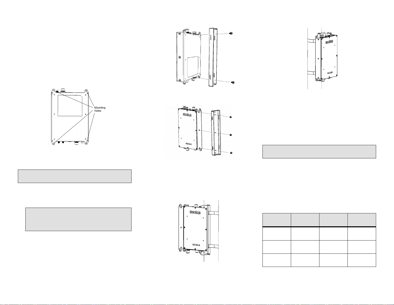
• Mounting bracket (purchased separately) for pole mounting
• Customer-supplied mounting bracket for DIN rail mounting
• Electric drill with drill bits and customer-supplied wall
anchors, flat washers, and hex nuts for flat-surface
mounting
AP Module Package Contents
The E510 AP Module installation package includes all of the
following:
• E510 Embedded Access Point Module
• Service Level Agreement/Limited Warranty Statement
• Declaration of Conformity
• Regulatory Statement
• Ruckus Wireless AP Getting Started Guide
• This Quick Setup Guide
FIGURE 1 E510 AP Module
Purchased Separately
The E510 requires an Antenna Cable Kit and Antenna Module
(Ruckus or third-party RF cables) to be purchased separately.
NOTE: BeamFlex is not supported when using third-party
RF cables.
Antenna Module
The E510 Antenna Module (Ruckus PN# 902-2101-0000)
consists of one vertically-polarized and one horizontally-
polarized antenna per band. Refer to the
E510 Antenna
Module Quick Setup Guide
for more information.
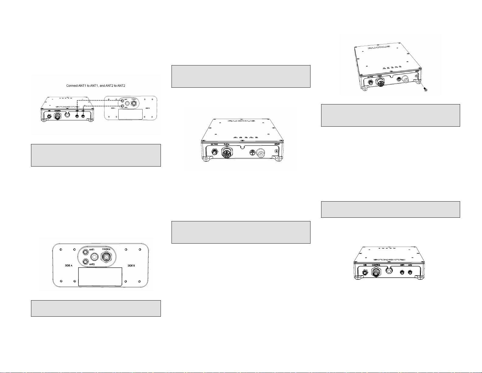
Antenna Cable Kit
Ruckus provides three different cable kits with different length
cables. Each kit contains two RF coaxial cables and one
Control cable. The RF cables are used to connect the AP
Module to the Antenna Module using two RP-SMA
connectors (each dual-band/single chain).
• 902-2000-0000 E510 Antenna Cable (60 cm length)
• 902-2001-0000 E510 Antenna Cable (150 cm length)
• 902-2002-0000 E510 Antenna Cable (300 cm length)
Copyright ©2018 ARRIS Enterprises LLC. All rights reserved. Page 1 of 4
Published March 2018, Part Number 800-71723-001 Rev A