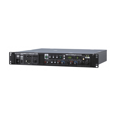
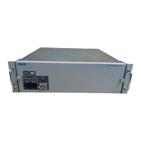
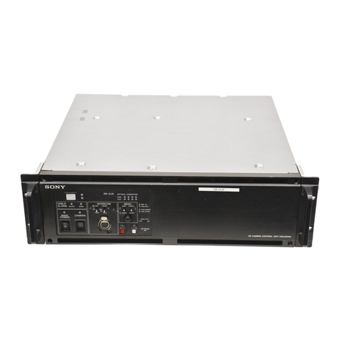
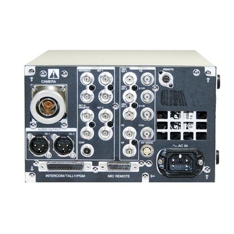
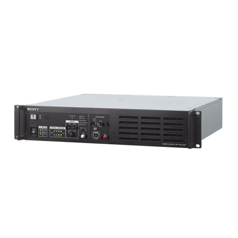
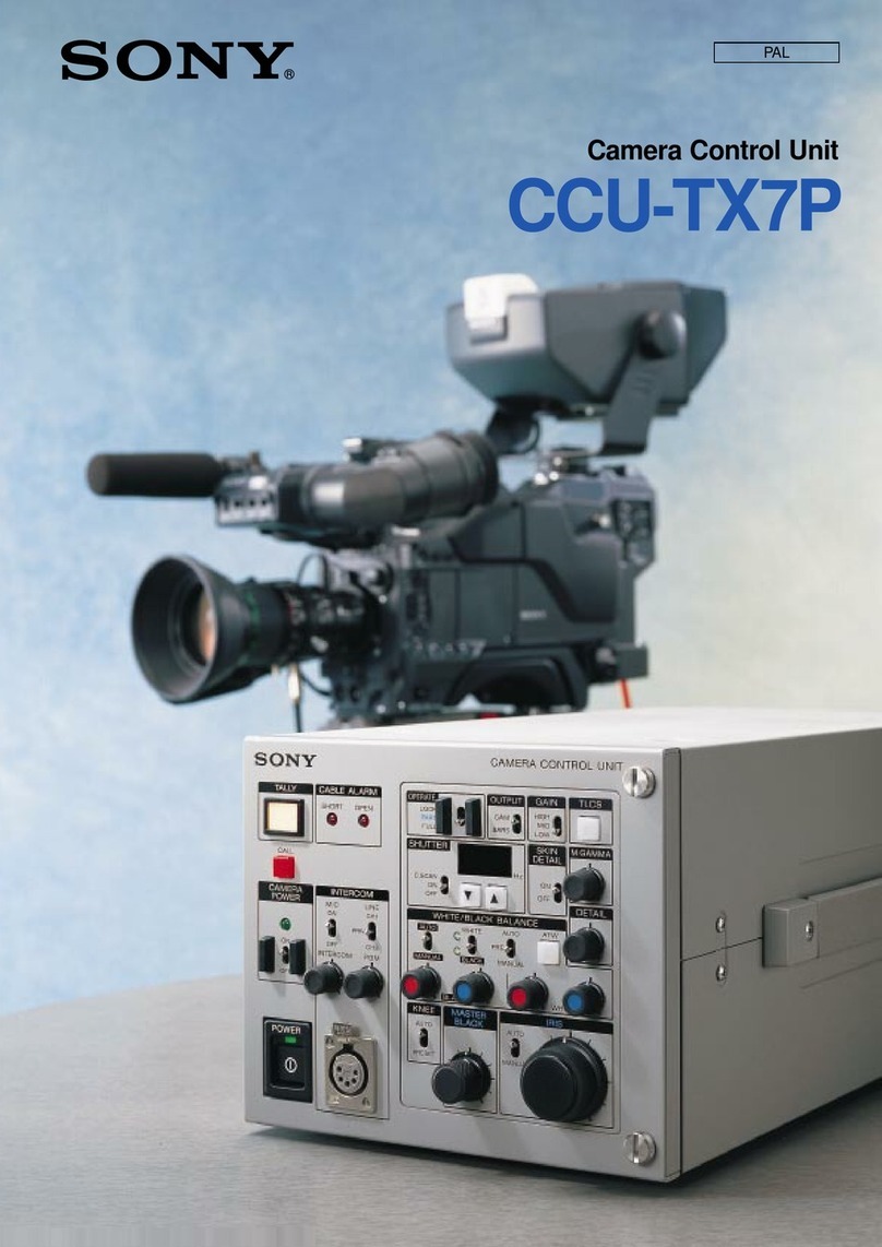
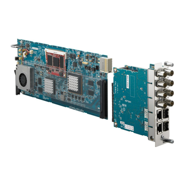
Sony HXCU-FB80 User manual

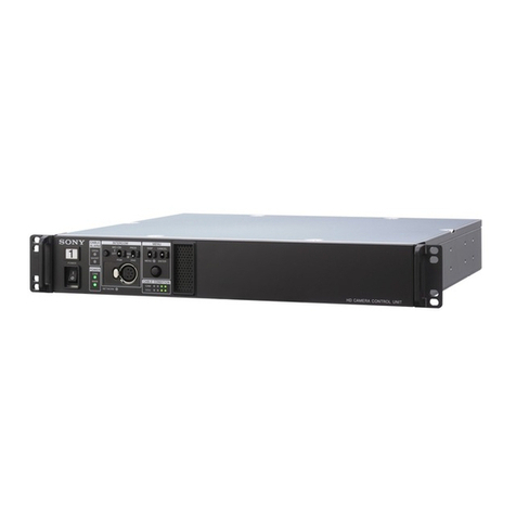
4K/HD CAMERA CONTROL UNIT
HXCU-FB80
SERVICE MANUAL
1st Edition

警告
このマニュアルは,サービス専用です。
お客様が,このマニュアルに記載された設置や保守,点検,修理などを行うと感電や火災,
人身事故につながることがあります。
危険をさけるため,サービストレーニングを受けた技術者のみご使用ください。
WARNING
This manual is intended for qualified service personnel only.
To reduce the risk of electric shock, fire or injury, do not perform any servicing other than that
contained in the operating instructions unless you are qualified to do so. Refer all servicing to
qualified service personnel.
WARNUNG
Die Anleitung ist nur für qualifiziertes Fachpersonal bestimmt.
Alle Wartungsarbeiten dürfen nur von qualifiziertem Fachpersonal ausgeführt werden. Um die
Gefahr eines elektrischen Schlages, Feuergefahr und Verletzungen zu vermeiden, sind bei
Wartungsarbeiten strikt die Angaben in der Anleitung zu befolgen. Andere als die angegeben
Wartungsarbeiten dürfen nur von Personen ausgeführt werden, die eine spezielle Befähigung
dazu besitzen.
AVERTISSEMENT
Ce manual est destiné uniquement aux personnes compétentes en charge de l’entretien. Afin
de réduire les risques de décharge électrique, d’incendie ou de blessure n’effectuer que les
réparations indiquées dans le mode d’emploi à moins d’être qualifié pour en effectuer d’autres.
Pour toute réparation faire appel à une personne compétente uniquement.
安全のために,周辺機器を接続する際は,過大電圧を持
つ可能性があるコネクターを以下のポートに接続しない
でください。
:LANコネクター
上記のポートについては本書の指示に従ってくだい。
For safety, do not connect the connector for peripheral
device wiring that might have excessive voltage to the
following port.
: LAN connector
Follow the instructions for the port.
HXCU-FB80

CAUTION
Danger of explosion if battery is incorrectly replaced.
Replace only with the same or equivalent type rec-
ommended by the manufacturer.
When you dispose of the battery, you must obey the
law in the relative area or country.
ATTENTION
Il y a danger d’explosion s’il y a remplacement incor-
rect de la batterie. Remplacer uniquement avec
une batterie du même type ou d’un type équivalent
recommandé par le constructeur.
Lorsque vous mettez la batterie au rebut, vous devez
respecter la législation en vigueur dans le pays ou la
région où vous vous trouvez.
VORSICHT
Explosionsgefahr bei Verwendung falscher Batterien.
Batterien nur durch den vom Hersteller empfohlenen
oder einen gleichwertigen Typ ersetzen.
Wenn Sie die Batterie entsorgen, müssen Sie die
Gesetze der jeweiligen Region und des jeweiligen
Landes befolgen.
注意
指定以外の電池に交換すると,破裂する危険があり
ます。
必ず指定の電池に交換してください。
使用済みの電池は,国または地域の法令に従って
処理してください。
FÖRSIKTIGHET!
Fara för explosion vid felaktigt placerat batteri.
Byt endast mot samma eller likvärdig typ av batteri,
enligt tillverkarens rekommendationer.
När du kasserar batteriet ska du följa rådande lagar
för regionen eller landet.
PAS PÅ
Fare for eksplosion, hvis batteriet ikke udskiftes
korrekt.
Udskift kun med et batteri af samme eller tilsvarende
type, som er anbefalet af fabrikanten.
Når du bortskaffer batteriet, skal du følge
lovgivningen i det pågældende område eller land.
HUOMIO
Räjähdysvaara, jos akku vaihdetaan virheellisesti.
Vaihda vain samanlaiseen tai vastaavantyyppiseen,
valmistajan suosittelemaan akkuun.
Noudata akun hävittämisessä oman maasi tai
alueesi lakeja.
FORSIKTIG
Eksplosjonsfare hvis feil type batteri settes i.
Bytt ut kun med samme type eller tilsvarende
anbefalt av produsenten.
Kasser batteriet i henhold til gjeldende avfallsregler.
⌞ᝅ
⌞ᝅ
ྸᴪᦘⲺ⭫⊖у↙⺤θቧՐᴿ⠼⛮Ⲻধ䲟Ⱦ
ᴪᦘж㊱ශᡌ䙖᧞㦆Ⲻ⭫⊖ශȾ
༺⨼⭫⊖ᰬθᗻ亱䚫ᆾީ൦ᡌളᇬⲺ⌋ᗁȾ
HXCU-FB80

Use of controls or adjustments or performance
of procedures other than those specified herein
may result in hazardous radiation exposure.
CAUTION
The HXCU-FB80 is classified as a CLASS 1 LASER
PRODUCT.
HXCU-FB80

Table of Contents
Manual Structure
Purpose of this manual....................................................................................................................5
Related manuals...........................................................................................................................5
Trademarks................................................................................................................................5
1. Service Overview
1-1. Location of Printed Wiring Boards............................................................................................1-1
1-2. Functions of Onboard Parts................................................................................................... 1-2
1-2-1. Description of Onboard LED Indicators................................................................................1-2
1-2-2. Functions of Onboard Switches........................................................................................ 1-4
1-3. Note on Replacement of Lithium Battery.....................................................................................1-6
1-4. Notes on Replacement of Circuit Board...................................................................................... 1-7
1-4-1. EEPROM Data......................................................................................................... 1-7
1-4-2. Actions to Be Taken after Board Replacement/Repair.................................................................1-7
1-5. Circuit Protection Parts........................................................................................................1-8
1-5-1. Thermistor.............................................................................................................. 1-8
1-6. Flexible Flat Cable and Coaxial Cable........................................................................................1-9
1-6-1. Connecting and Disconnecting Flexible Card Wires...................................................................1-9
1-6-2. Disconnecting/Connecting Fine-Wire Coaxial Cable.................................................................1-10
1-7. Lead-free Solder............................................................................................................. 1-12
2. Periodic Maintenance and Inspection
2-1. Cleaning of Connector/Cable................................................................................................. 2-1
2-1-1. Cleaning Connectors/Cables of NEUTRIK............................................................................ 2-1
2-1-2. Cleaning Connectors/Cables of LEMO................................................................................ 2-3
3. Replacement of Main Parts
3-1. Tightening Torque.............................................................................................................3-1
3-2. Cover.......................................................................................................................... 3-2
3-3. Front Panel Assembly.........................................................................................................3-3
3-4. PS-934 Board..................................................................................................................3-4
3-5. DC Fan........................................................................................................................ 3-6
3-6. Switching Regulator (Large)..................................................................................................3-8
3-7. Switching Regulator (Small)..................................................................................................3-9
3-8. AT-196 Board and Lithium Battery..........................................................................................3-10
3-9. Optical Connector Assembly................................................................................................ 3-11
3-9-1. Neutrik Model.........................................................................................................3-11
3-9-2. LEMO Model......................................................................................................... 3-12
3-10. CN-3958 Board.............................................................................................................. 3-15
3-11. CN-3968 Board.............................................................................................................. 3-16
3-12. DPR-386 Board..............................................................................................................3-17
3-13. CN-3972 Board.............................................................................................................. 3-19
3-14. SW-1736 Board..............................................................................................................3-20
3-15. CN-3985 Board.............................................................................................................. 3-22
HXCU-FB80 1

3-16. LED-544 Board..............................................................................................................3-23
3-17. LED-545 Board..............................................................................................................3-24
4. Electrical Alignment
4-1. Preparations................................................................................................................... 4-1
4-1-1. Equipment Required....................................................................................................4-1
4-1-2. Precautions on Adjustments............................................................................................4-1
4-1-3. Connection of Equipment.............................................................................................. 4-1
4-1-4. Initial Settings.......................................................................................................... 4-2
4-2. Reference Signal System Adjustment.........................................................................................4-3
4-2-1. 27 MHz VCO Free-Running Adjustment.............................................................................. 4-3
4-3. Video Signal System Adjustment............................................................................................. 4-4
4-3-1. VBS Output Level Adjustment.........................................................................................4-4
4-3-2. PIX Output Level Adjustment..........................................................................................4-4
4-4. Cable Driver Adjustment......................................................................................................4-6
4-4-1. Adjusting 12G-SDI Amplitude.........................................................................................4-6
4-4-2. Adjusting 3G-SDI Amplitude.......................................................................................... 4-6
4-4-3. Adjusting HD-SDI Amplitude..........................................................................................4-7
5. Software Update
5-1. Upgrading the Software Programs............................................................................................ 5-1
5-1-1. Updating the Main Program ........................................................................................... 5-1
5-1-2. Updating the BOOT Program.......................................................................................... 5-2
5-2. Writing and Rewriting the PLD Internal Data................................................................................ 5-4
5-2-1. Corresponding PLDs................................................................................................... 5-4
6. Maintenance Mode
6-1. Preparations................................................................................................................... 6-1
6-1-1. Starting/Exiting the Maintenance Mode................................................................................6-1
6-1-2. Memory Stick...........................................................................................................6-2
6-2. VE OPERATION Menu.......................................................................................................6-3
6-3. MAINTENANCE Menu.....................................................................................................6-13
7. Circuit Description
7-1. Circuit Description of Each Board............................................................................................7-1
7-1-1. AT-196 Board...........................................................................................................7-1
7-1-2. CN-3958 Board.........................................................................................................7-1
7-1-3. CN-3968 Board.........................................................................................................7-1
7-1-4. CN-3972 Board.........................................................................................................7-1
7-1-5. CN-3985 Board.........................................................................................................7-2
7-1-6. DPR-386 Board.........................................................................................................7-2
7-1-7. LED-544 Board.........................................................................................................7-2
7-1-8. LED-545 Board.........................................................................................................7-2
7-1-9. PS-934 Board...........................................................................................................7-2
7-1-10. SW-1736 Board.........................................................................................................7-3
HXCU-FB80 2

8. Spare Parts
8-1. Note on Repair Parts.......................................................................................................... 8-1
8-2. Exploded Views............................................................................................................... 8-2
Overall............................................................................................................................... 8-2
PS Block............................................................................................................................. 8-3
Chassis-1.............................................................................................................................8-4
DPR Block...........................................................................................................................8-6
Chassis-2.............................................................................................................................8-7
Front Panel...........................................................................................................................8-8
8-3. Supplied Accessories .........................................................................................................8-9
9. Diagrams
Overall..................................................................................................................................9-1
Frame Wiring...........................................................................................................................9-3
Revision History
HXCU-FB80 3


Manual Structure
Purpose of this manual
This manual is intended for the use of the system engineers and the service engineers, and provides the limited
information for block service and the information related to maintenance of the unit, service overview, periodic
maintenance and inspection, replacement of main parts, electrical alignment, software update, maintenance mode, circuit
description, spare parts, block diagram, frame wiring, and etc. .
Related manuals
The following manuals are available for this model.
If any of these manuals is required, please contact your local Sony Sales Office/Service Center.
• Operating Instructions CD-ROM (supplied with the unit)
This manual contains information required to operate and use the unit.
• Installation Manual (available on request)
This manual provides the information on installing the unit.
• Factory Service Manual (available on request)
This manual provides the limited information for component service and the information related to maintenance
of the unit.
Trademarks
Trademarks and registered trademarks described in this manual are as follows.
• FRAM is a registered trademark of Ramtron International Corporation.
Other system names and product names written in this manual are usually registered trademarks or trademarks of
respective development manufacturers.
HXCU-FB80 5


Section 1
Service Overview
1-1. Location of Printed Wiring Boards
DPR-386
LED-544
SW-1736
CN-3985
PS-934
LED-545
CN-3972
AT-196
CN-3968
CN-3958
HXCU-FB80 1-1

1-2. Functions of Onboard Parts
1-2-1. Description of Onboard LED Indicators
AT-196 board
D202
D700
ABCDEFG
1
2
3
4
5
AT-196 board (Side A)
Ref.No. Name Color Description Normal
state
D202 MS-LED Red/Green Indicates state of access to the memory stick.
Lit red: Access to the memory stick in progress. Do
not remove the memory stick.
Lit green: The inserted memory stick can be re-
moved.
—
D700 CONF DONE Red Lights when there is a problem with the configu-
ration of any FPGA (IC400) on the AT-196 board.
Off
HXCU-FB80 1-2

DPR-386 board
D114
D701
DPR-386 board (Side A)
ABCDEF
1
2
3
4
5
6
Ref.No. Name Color Description Normal
state
D114 PWR Green Lights when all power voltages on the DPR-386
board are normal.
Lit
D701 CONF DONE Red Lights when there is a problem with the configu-
ration of any FPGA (IC600, IC2300) on the
DPR-386 board.
Off
HXCU-FB80 1-3

1-2-2. Functions of Onboard Switches
AT-196 board
S200
ABCDEFG
1
2
3
4
5
AT-196 board (Side A)
Note
Do not change the settings of unused switches.
Ref.No. Name Bit Description Factory
setting
S200 VerUp 1 Used to enable software upgrade using a memory
stick.
OFF
PLD VerUp 2 Used to enable PLD upgrade using a memory stick. OFF
NORMAL/DEBUG 3 Not used OFF
NORMAL/DEBUG 4 Not used OFF
HXCU-FB80 1-4

PS-934 board
S002
AB
1
2
3
4
5
6
PS-934 board (Side A)
Ref.No. Name Bit Description Factory
setting
S002 OFF 1 DC-DC control ON/OFF for camera power output
When this switch is set to ON, 48 V power is always
output.
OFF
HXCU-FB80 1-5

1-3. Note on Replacement of Lithium Battery
A lithium battery is mounted on the AT-196 board to backup the real time clock (RTC). If a battery comes to the lifetime,
then RTC stops. Therefore, replace the battery and re-set DATE/TIME on the C12 DATE page of the CCU
CONFIGURATION menu. (Refer to “Setup Menu” in the Operating Instructions.)
Part No. Name Use
!
1-528-174-74 BATTERY, LITHIUM (CR2032
TYPE)
For real time clock (RTC) backup
CAUTION
In replacing, ensure that the battery is installed with “+” and “-” poles connected to the correct terminals.
Improper connection may cause an explosion or leakage of fluid.
HXCU-FB80 1-6

1-4. Notes on Replacement of Circuit Board
1-4-1. EEPROM Data
The table below lists data retained in the EEPROM on respective boards.
Note
The part number listed in “Spare Parts” is for EEPROM which is not programmed. Therefore, program a new EEPROM
after replacement. For details, contact your local Sony Sales Office/Service Center.
Board name Ref. No. Stored data
AT-196 IC205, IC206 MAC address, etc. and board adjustment data
DPR-386 IC309 Serial number and board adjustment data
1-4-2. Actions to Be Taken after Board Replacement/Repair
Board name Action
AT-196 • Re-setting of model name and destination (Refer to “6-3. MAINTENANCE Menu”)
• Re-setting of DATE/TIME after replacement of lithium battery (Refer to “1-3. Note on Re-
placement of Lithium Battery”)
DPR-386 • Re-setting of serial number (Refer to “6-3. MAINTENANCE Menu”)
• Video Signal System Adjustment (Refer to “4-3. Video Signal System Adjustment”)
• 27 MHz VCO Free-Running Adjustment (Refer to “4-2-1. 27 MHz VCO Free-Running Ad-
justment” )
HXCU-FB80 1-7

1-5. Circuit Protection Parts
1-5-1. Thermistor
This unit is equipped with positive-characteristic thermistors (power thermistors) as circuit protection elements.
The positive-characteristic thermistor limits the electric current flowing through the circuit as the internal resistance
increases when an excessive current flows or when the ambient temperature increases.
If the positive-characteristic thermistor works, turn off the main power of the unit and inspect the internal circuit of the
unit. After the cause of the fault is eliminated and the positive-characteristic thermistor is cooled down, turn on the main
power again. The unit works normally. It takes about one minute to cool down the positive-characteristic thermistor
after the main power is turned off.
Board Ref. No. Address Part No. Holding current
AT-196 TH100 C-1
!
1-802-108-11 1.5 A/20 ℃
TH200 B-5
!
1-771-845-21 200 mA/20 ℃
DPR-386 THP1 F-6
!
1-771-845-21 500 mA/25 ℃
THP2 F-6
!
1-802-243-11 1.75 A/20 ℃
THP20 B-4
!
1-771-845-21 500 mA/25 ℃
THP100 F-3
!
1-804-458-21 500 mA/20 ℃
THP102 F-2
!
1-804-987-21 2.5 A/20 ℃
THP103 F-4
!
1-804-616-21 1.1 A/20 ℃
THP105 E-5
!
1-803-615-21 500 mA/20 ℃
THP106 E-4
!
1-804-458-21 500 mA/20 ℃
THP107 E-4
!
1-804-616-21 1.1 A/20 ℃
THP108 E-4
!
1-804-616-21 1.1 A/20 ℃
THP109 F-4
!
1-803-615-21 500 mA/20 ℃
THP110 F-4
!
1-803-615-21 500 mA/20 ℃
THP111 E-4
!
1-804-616-21 1.1 A/20 ℃
THP114 F-2
!
1-804-987-21 2.5 A/20 ℃
THP115 E-5
!
1-804-616-21 1.1 A/20 ℃
THP118 F-5
!
1-804-616-21 1.1 A/20 ℃
THP121 F-5
!
1-804-616-21 1.1 A/20 ℃
THP122 F-5
!
1-804-616-21 1.1 A/20 ℃
PS-934 TH201 B-2
!
1-811-308-21 1.1 A/20 ℃
HXCU-FB80 1-8

1-6. Flexible Flat Cable and Coaxial Cable
1-6-1. Connecting and Disconnecting Flexible Card Wires
This unit uses two types of connectors for flexible card wire.
Notes
• Bending a flexible card wire significantly shortens its lifetime. Handle flexible card wires very carefully.
• A flexible card wire consists of conductive surface and insulated surface. Note that the circuit does not work if a
flexible card wire is connected in wrong orientation of conductive surface and insulated surface.
• Do not insert the flexible card wire sideways.
• Make sure that the conductive surface of flexible card wires is free of dust and dirt.
Connecting/Disconnecting Flexible Card Wire (Type A Connector)
Isolation surface
(blue)
Connector
Open/close
section
Isolation surface
(blue)
Connector
Open/close
section
ConnectingDisconnecting
Disconnection
1. Open the connector open/close section to release the lock.
Note
Do not open the connector open/close section 90 degrees or more so as not to damage the connector.
2. Pull the flexible card wire.
Connection
1. Insert the flexible card wire fully into the connector.
2. Push the connector open/close section to lock the flexible card wire.
Connecting/Disconnecting Flexible Card Wire (Type B Connector)
Isolation surface
(blue)
Isolation surface
(blue)
Open/close section Open/close section
ConnectingDisconnecting
Connector Connector
HXCU-FB80 1-9

Disconnection
1. Open the connector open/close section to release the lock.
Note
Do not open the connector open/close section 90 degrees or more so as not to damage the connector.
2. Pull the flexible card wire.
Connection
1. Insert the flexible card wire fully into the connector.
2. Push the connector open/close section to lock the flexible card wire.
1-6-2. Disconnecting/Connecting Fine-Wire Coaxial Cable
Note
• Be very careful when handling the fine-wire coaxial cable so that fine wires are not disconnected.
• When disconnecting the fine-wire coaxial cable, be sure to hold the connector. Do not attempt to pull the cable.
• Check that the contact surface of the fine-wire coaxial cable connector is not contaminated.
Type A
Disconnecting
Hold the connector to disconnect.
Do not attempt to disconnect by
pulling the cable.
OK
NG
A
Connector
Pull-bar
Fine-wire
coaxial cable
1. Raise the pull-bar in the direction of arrow A to unlock it.
2. Hold both sides of the fine-wire coaxial cable connector, and pull the connector straight to disconnect it.
HXCU-FB80 1-10
Other manuals for HXCU-FB80
1
Table of contents
Other Sony Control Unit manuals
Popular Control Unit manuals by other brands

WAM
WAM LBC Series Assembly and main instructions for use and maintenance

Hinkley
Hinkley 980040FWH installation instructions

Pickering
Pickering SYSTEM 10 user manual

SYRUS
SYRUS MDNET Install and operation instructions

Telit Wireless Solutions
Telit Wireless Solutions GE910 Hardware user's guide

Rodix
Rodix FEEDER CUBE FC-44 Plus Adjustments and Set Up