Arris GRILLVAPOR 550EL User manual

550EL-770EL-700EL-710EL-900EL-910EL
Installation and operation manual
English
ELECTRIC GRILL
EEC DIRECTIVE 73/23 – 93/68 – 89/336
ATTENTION: CHARCOAL OR SIMILAR COMBUSTIBLES MUST
NOT BE USED WITH THESE APPLIANCES


3 0709
TABLE OF CONTENTS
INSTALLATION
Installation instruction ....................................................................pag. 4
Laws, technical regulations an directive . . . . . . . . . . . . . . . . . . . . . . . . . . . . . . . . . . . . . . . . . . . . . . . . . . .pag. 4
Electricalconnection .....................................................................pag. 4
Equipotencial connection.................................................................pag. 5
Stating up ................................................................................pag. 5
INSTRUCTIONS FOR USE
Switch-on................................................................................pag. 5
Special instruction ........................................................................pag. 5
Cleaningandmaintenance ...............................................................pag. 5
What to do if the grill is not being used . . . . . . . . . . . . . . . . . . . . . . . . . . . . . . . . . . . . . . . . . . . . . . . . . . .pag. 6
Whattodoifafaultoccurs ...............................................................pag. 6
MAINTENANCE
Accestotheelectricalbox................................................................pag. 6
Accestotheelectricalresistance..........................................................pag. 6
Details ...................................................................................pag. 7
Howraisethegrillsurface ................................................................pag. 9
Fastening of the feet on the cabinet.......................................................pag. 10
Installation of a cabinet ...................................................................pag. 10
Technicalcharacteristics..................................................................pag. 11
Wiring diagrams ..........................................................................pag. 12
Tableofdimensions ......................................................................pag. 17
Requireduserinformation................................................................pag. 23

0709 4
INSTALLATION INSTRUCTIONS
THIS APPLIANCE MUST ONLY BE USED FOR THE PURPOSE IT HAS BEEN DESIGNED FOR.
The technical specifications plate is located on the controls front panel and contains all information necessary for connection.
LAWS, TECHNICAL REGULATIONS AND DIRECTIVES
The appliance must be installed in compliance with the following regulations:
1 - CURRENT SAFETY REGULATIONS
2 - INSTALLATION REGULATIONS, CEI STANDARDS
INSTALLATION
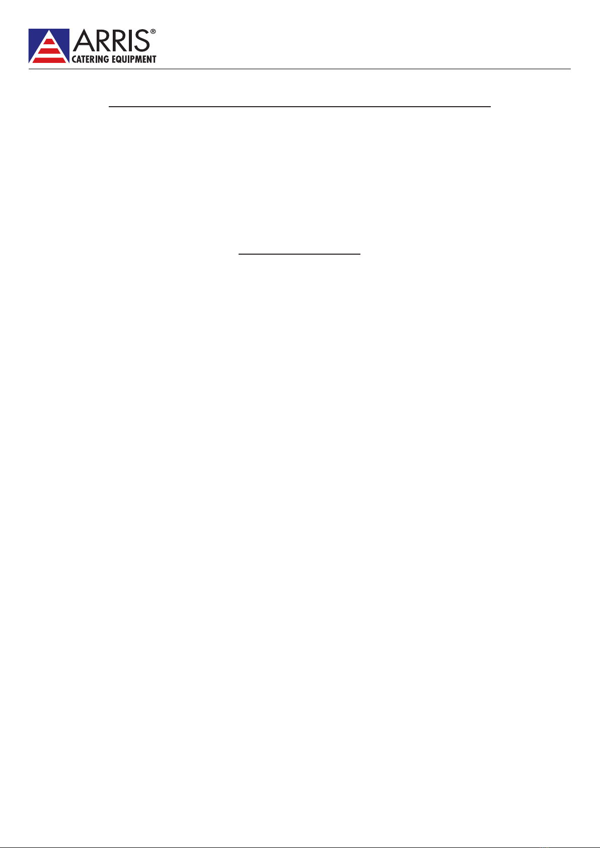
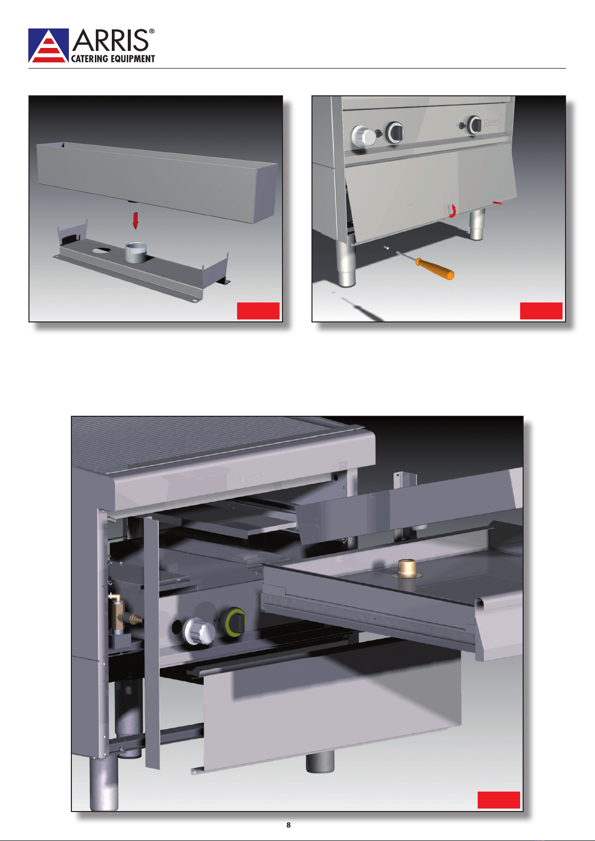
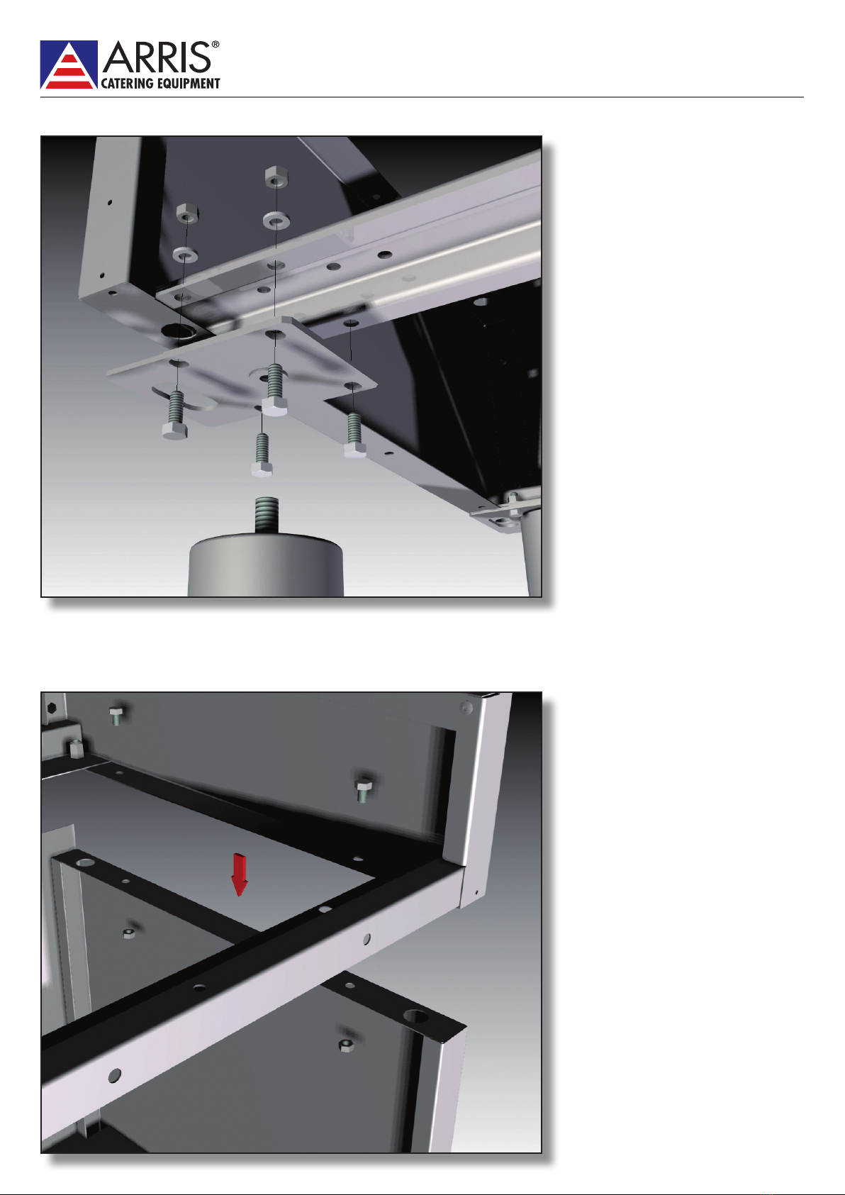
Unpack the appliance, position it, level it and adjust the height if necessary by means of the adjustable feet (fig. 1). Remove the
protective film from the outer panels.
The master switch or socket must be near the appliance and easy to access.
You are advised to position the appliance below an extraction hood in order to ensure rapid elimination of the greasy vapours.
If the appliance is positioned near walls, partitions, kitchen units, decor panels etc., they should be made of non-flammable
material or otherwise covered with non-flammable material.
All fire regulations must be complied with.
Model GV 819EL must be connected to a 3/8” diameter water inlet pipe and a 1 1/4” diameter water drain pipe; see table of
dimensions (1-b).
Installation, starting up and maintenance of the appliance must be performed by qualified personnel. All installation work must
be performed in compliance with current regulations.
The manufacturer declines all liability for faulty operation due to incorrect installation.
Caution: In the event a fixed equipment does not have a power lead and plug, or any other device to disconnect it from
the electric board, which has sufficient tripping between contacts to ensure total disconnection in category III overvoltage
circumstances, the instructions must state that these disconnection devices must be installed in the electric board in compliance
with installation regulations in force.
ELECTRICAL CONNECTION
The appliance is delivered with H07 RN-F type connection cable.
If the cable has to be replaced, proceed as follows:
1) Disconnect the power supply.
2) Slide out the ventilation element end cover and front panel (fig. 3).
3) Raise the grill surface approximately 60° via the handle and prop open by means of the support (fig. 2).
4) Slide out the water tray (fig.6).
5) Remove the electrical box upper panel by taking the screws out (fig. 7).
6) Disconnect the line input terminal block cable (ref. 1 in wiring diagram) inside the rear part of the electrical box.
7) Loosen the cable grip and slide the cable out.
8) Slide the new connection cable through the cable grip, connect the leads to the corresponding terminal in the terminal block
and secure them.
9) Secure the cable with the cable grip and refit all parts in points 4 and 3 (fig. 4) in reverse order. The earth lead must be longer
than the others so that if the cable grip breaks, it detaches after the power leads.
10) Lower the grill surface via the handle .
11) Replace the ventilation element end cover and front panel.
N.B. The connection cable must be of type H07 RN-F (minimum requirement) with section adequate for the power of the
appliance, see (11) table of technical specifications.

5 0709
EQUIPOTENTIAL
The appliance must be connected to an equipotential system.
The connection screw is located on the rear part of the appliance and marked by the symbol:
Caution: the manufacturer is not liable and is not required to compensate under the guarantee for damage caused by
inadequate installation and failure to follow the installation instructions.
STARTING UP
Before using the appliance for the first time it must be carefully cleaned, see paragraph “Cleaning and Maintenance”.
Check the connection of the appliance and start it following the instructions.
INSTRUCTIONS FOR USE
Caution: the appliance should not be left operating unmanned.
Remember that the grill surface becomes very hot during use.
GRILLVAPOR® appliances are designed for grilling meat, fish, vegetables, cheese etc.
SWITCHON
Check that the water tray is inserted. Fill the tray with water. In the 910EL series it is filled by opening the chromium-plated water
tap with blue band (fig. 7).
Check that the grill surface is fully lowered and resting horizontally on the Grillvapor body.
Turn on the switch upstream of the appliance.
In model GV819EL it is possible to operate the grill surface in two parts at separate temperatures.
The green light indicates that the appliance is powered.
To switch the appliance on, turn the yellow knob from position “0” to “MAX”.
The yellow/orange light indicates operation of the heating element; when it goes out it means that the temperature has been
reached. In the “MAX” position the yellow/orange light remains on continuously.
To switch the appliance off, set the yellow knob to “0”.
SPECIAL INSTRUCTIONS
During use of the Grillvapor you are advised to use a steel brush to clean the grill surface.
To avoid overheating, unnecessary smoke and danger of the oil in the collecting pan catching fire, always cook with the tray
below the grill surface full of water, keeping an eye on the level during cooking (fig. 4 and fig.6).
CLEANING AND MAINTENANCE
Caution: during cleaning do not wash the outside of the appliance with direct or high pressure jets of water.
Thoroughly clean the appliance every evening after work. Daily cleaning will ensure perfect operation and long life of the grill.
Disconnect the appliance before beginning cleaning. The steel parts should be washed with hot water and neutral detergent,
thoroughly rinsed to eliminate all traces of detergent and then dried with a dry cloth.
Do not use abrasive or corrosive detergents.
Cleaning of the parts in contact with the food is simple: the ventilation element end cover and front panel can be pulled out
easily and the grill surface can be raised 60° to facilitate access to the lower part - a handle with catch is provided to facilitate
raising of the grill surface and the support inside the appliance on the right props the grill surface open (fig. 2). The water tray
can be pulled out to facilitate cleaning (fig. 5). In the 710EL and 910EL series the tray is positioned on sliding rails and can also be
pulled out to facilitate cleaning (fig.6). In addition, the two aforementioned series have a drain tray under the water tray which is
also extractable for thorough cleaning (fig.7).
This manual suits for next models
5
Table of contents
Other Arris Grill manuals
Popular Grill manuals by other brands

Landmann
Landmann Avalon PTS Plus 5.1 Plus 12122 Assembly and operating manual

Kenyon
Kenyon B70200 owner's manual

Better Homes and Gardens
Better Homes and Gardens GBC1486W owner's manual

Orbegozo
Orbegozo GR 2300 instruction manual

bora
bora PT11 Operating and installation instructions

Klarstein
Klarstein 10031664 manual

Garland
Garland MWE3W Installation and operation manual

Char-Broil
Char-Broil 463722714 Product guide

MPM
MPM MOP-03 user manual

Kenmore
Kenmore 415.16123800 Use and care guide

Tucker Barbecues
Tucker Barbecues GTR Series Assembly, installation and operating instructions

Monogram
Monogram ZGG540NCP1SS owner's manual