Arris GRILLVAPOR Series User manual

GRILLVAPOR
550EL-770EL-700EL-710EL-900EL-910EL
ELECTRIC GRILL
EEC DIRECTIVE 73/23 – 93/68 – 89/336
Installation and operation manual
ENGLISH
TABLE OF CONTENTS
INSTALLATION INSTRUCTIONS pag. 02
INSTALLATION pag. 02
LAWS,TECHNICAL REGULATIONS AN DIRECTIVE pag. 02
ELECTRICAL CONNECTION pag. 02
EQUIPOTENCIAL CONNECTION pag. 03
STATING UP pag. 03
INSTRUCTIONS FOR USE pag. 03
SWITCH-ON pag. 03
SPECIAL INSTRUCTION pag. 03
CLEANIG AND MAINTENANCE pag. 04
WHAT TO DO IF THE GRILL IS NOT BEING USED pag. 04
WHAT TO DO IF A FAULT OCCURS pag. 04
MAINTENANCE pag. 04
A
CCES TO ELECTRICALBOX AND ELECTRICAL RESISTANCE pag. 04
DETAILS pag. 05-06
HOW RAISE THE GRILL SURFACE pag. 07
FISSAGGIO PIEDINI – INSTALLAZIONE DI UN MOBILE pag. 09
TECHNICAL CHARACTERISTICS pag. 08
WIRING DIAGRAMS pag. 09-13
TABLE OF DIMENSIONS pag. 14-19

2
THIS APPLIANCE MUST ONLY BE USED FOR THE PURPOSE IT HAS BEEN DESIGNED FOR.
(2) INSTALLATION INSTRUCTIONS
The technical specifications plate is located on the controls front panel and contains all information necessary
for connection. (3) INSTALLATION
Unpack the appliance, position it, level it and adjust the height if necessary by means of the adjustable feet (fig.
1). Remove the protective film from the outer panels. The master switch or socket must be near the appliance
and easy to access. You are advised to position the appliance below an extraction hood in order to ensure
rapid elimination of the greasy vapours.
If the appliance is positioned near walls, partitions, kitchen units, decor panels etc., they should be made of
non-flammable material or otherwise covered with non-flammable material.
All fire regulations must be complied with.
Model GV 819EL must be connected to a 3/8” diameter water inlet pipe and a 1 1/4” diameter water drain pipe;
see table of dimensions (1-b).
(3-a) Laws, technical regulations and directives
The appliance must be installed in compliance with the following regulations:
1 - CURRENT SAFETY REGULATIONS
2 - INSTALLATION REGULATIONS, CEI STANDARDS
(3-b) Installation
Installation, starting up and maintenance of the appliance must be performed by qualified personnel. All
installation work must be performed in compliance with current regulations.
The manufacturer declines all liability for faulty operation due to incorrect installation.
In the event a fixed equipment does not have a power lead and plug, or any other device to disconnect it
from the electric board, which has sufficient tripping between contacts to ensure total disconnection in category
III overvoltage circumstances, the instructions must state that these disconnection devices must be installed in
the electric board in compliance with installation regulations in force
(3-c) Electrical connection
The appliance is delivered with H07 RN-F type connection cable.
If the cable has to be replaced, proceed as follows:
1) Disconnect the power supply.
2) Slide out the ventilation element end cover and front panel (fig. 3).
3) Raise the grill surface approximately 60° via the handle and prop open by means of the support (fig. 2).
4) Slide out the water tray (fig.6).
5) Remove the electrical box upper panel by taking the screws out (fig. 7).
6) Disconnect the line input terminal block cable (ref. 1 in wiring diagram) inside the rear part of the electrical
box.
7) Loosen the cable grip and slide the cable out.
8) Slide the new connection cable through the cable grip, connect the leads to the corresponding terminal in
the terminal block and secure them.
9) Secure the cable with the cable grip and refit all parts in points 4 and 3 (fig. 4) in reverse order. The earth
lead must be longer than the others so that if the cable grip breaks, it detaches after the power leads.
10) Lower the grill surface via the handle .
11) Replace the ventilation element end cover and front panel.
N.B. The connection cable must be of type H07 RN-F (minimum requirement) with section adequate for the
power of the appliance, see (1) table of technical specifications.

3
(4) EQUIPOTENTIAL
The appliance must be connected to an equipotential system. The connection screw is located on the rear part
of the appliance and marked by the symbol
Caution: the manufacturer is not liable and is not required to compensate under the guarantee for damage
caused by inadequate installation and failure to follow the installation instructions.
(5) STARTING UP
Before using the appliance for the first time it must be carefully cleaned, see paragraph (7) Cleaning and
Maintenance.
Check the connection of the appliance and start it following the instructions.
(6) INSTRUCTIONS FOR USE
Caution: the appliance should not be left operating unmanned.
- Remember that the grill surface becomes very hot during use.
GRILLVAPOR appliances are designed for grilling meat, fish, vegetables, cheese etc.
(6-a) Switch-on
Check that the water tray is inserted. Fill the tray with water. In the 910EL series it is filled by opening the
chromium-plated water tap with blue band (fig. 7).
Check that the grill surface is fully lowered and resting horizontally on the Grillvapor body.
Turn on the switch upstream of the appliance.
In model GV819EL it is possible to operate the grill surface in two parts at separate temperatures.
The green light indicates that the appliance is powered.
To switch the appliance on, turn the yellow knob from position “0” to “MAX”.
The yellow/orange light indicates operation of the heating element; when it goes out it means that the
temperature has been reached. In the “MAX” position the yellow/orange light remains on continuously.
To switch the appliance off, set the yellow knob to “0”.
(6-b) Special instructions
During use of the Grillvapor you are advised to use a steel brush to clean the grill surface.
To avoid overheating, unnecessary smoke and danger of the oil in the collecting pan catching fire, always cook
with the tray below the grill surface full of water, keeping an eye on the level during cooking (fig. 4).

4
(7) CLEANING AND MAINTENANCE
Caution: during cleaning do not wash the outside of the appliance with direct or high pressure jets of water.
Thoroughly clean the appliance every evening after work.
Daily cleaning will ensure perfect operation and long life of the grill.
Disconnect the appliance before beginning cleaning. The steel parts should be washed with hot water and
neutral detergent, thoroughly rinsed to eliminate all traces of detergent and then dried with a dry cloth. Do not
use abrasive or corrosive detergents.
Cleaning of the parts in contact with the food is simple: the ventilation element end cover and front panel can
be pulled out easily and the grill surface can be raised 60° to facilitate access to the lower part - a handle with
catch is provided to facilitate raising of the grill surface and the support inside the appliance on the right props
the grill surface open (fig. 2).
The water tray can be pulled out to facilitate cleaning (fig. 6).
In the series 910EL the tray is fitted on runners and can be taken out for cleaning (fig. 6).
(7-a) What to do if the grill is not being used
Thoroughly clean and dry the appliance following the instructions. Disconnect from the power supply.
(7-b) What to do if a fault occurs
If a fault occurs switch the appliance off, disconnect via the device upstream of the appliance and notify the
technical support service. (8) MAINTENANCE
(Only for qualified persons)
All maintenance work must be performed by qualified personnel only. Before beginning work, unplug or turn off
the switch upstream. (8-a) Access to electrical box
To access the electrical components inside the electrical box and the control elements and pilot lights, see the
procedure described in paragraph (3-c) electrical connection points 1, 2, 3, 4 and 5.
To remove the controls dashboard, unscrew the self-tapping screws at the top and bottom.
(8-b) Access to electrical resistances
The electrical resistances are clad in stainless steel 18/10 - AISI 304 and are housed in special profile tubes. If
a resistance breaks, ensure that the electricity supply is disconnected.
The electrical resistances are connected in groups of four per phase; once you have identified the cold area of
the grill surface, proceed as follows:
1) Slide out the ventilation element end cover and front panel (fig. 3).
2) Raise the grill surface approx. 60° by means of the handle and prop open by means of the support (fig. 2).
3) Unscrew the two M6 screws on the front resistance cover and remove it (fig. 2).
4) Unscrew the front resistance stop and remove it.
5) Unscrew the rear resistance cover screw and remove it.
6) Unscrew the screws of the resistance unit in the cold area.
7) Check the resistances one by one with a tester until you find the one not working.
8) Once you have identified the resistance, slide it out of the front of the grill surface and replace with a new
one.
9) Refit all the above components in reverse order.

5
FIG 01 FIG 02
FIG 03 FIG 04
FIG 05 FIG 06

6
FIG 07 FIG 08
FIG 09

7
HOW RAISE THE GRILL SURFACE BY MEANS OF THE HANDLE
1 2
3 4
1 Put the handle between the heating elements
2 Turn the handle of 90° towards the left
3 Pull up to lift the cooking surface
4 Fix the cooking surface with the special support

8
TECHNICAL CHARACTERISTICS
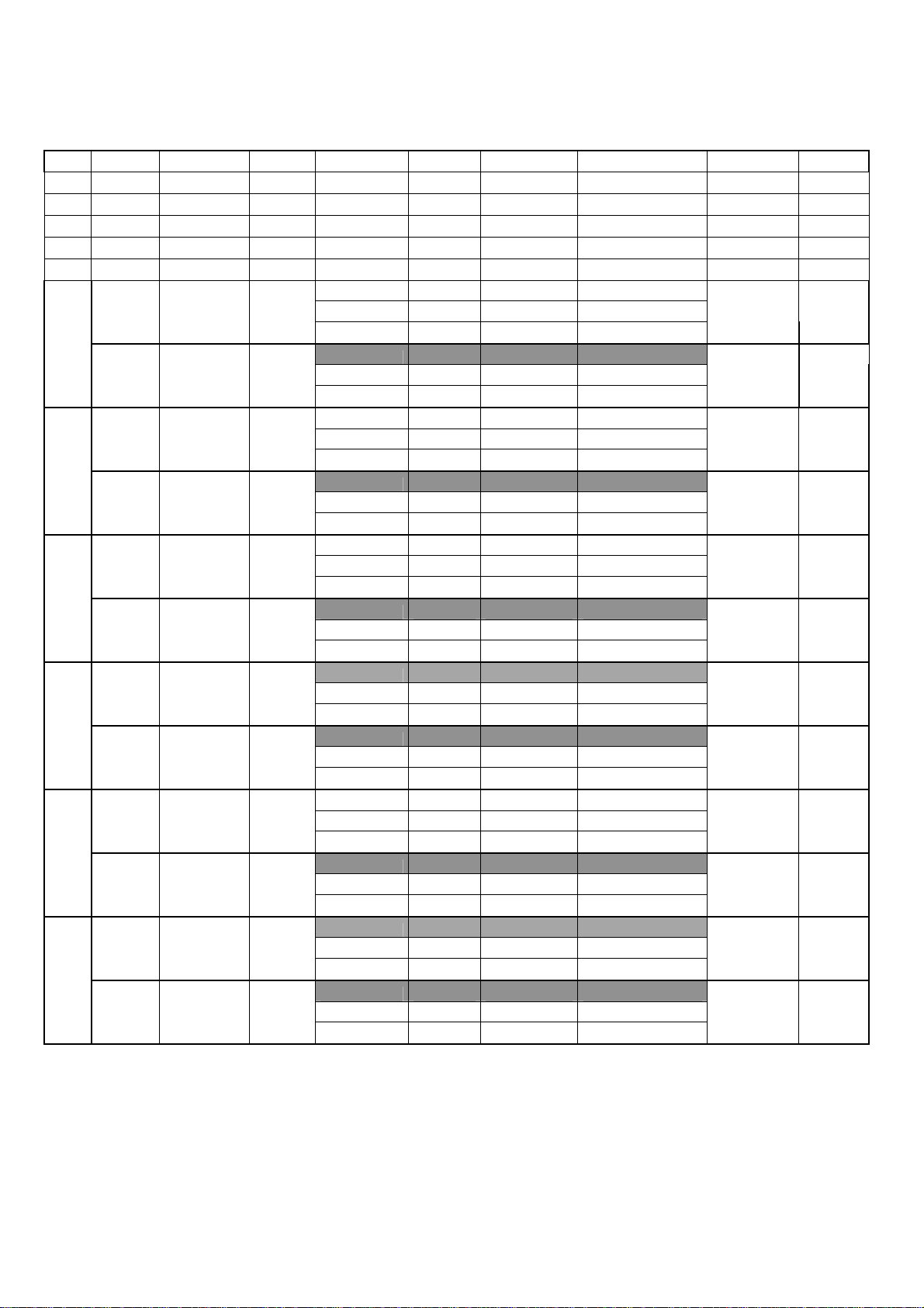
IT Modelli Dimensioni Cottura Alimentazione Cavo Tipo di Cavo Assorbimento max. Potenza Max. Frequenza
GB Model Dimensions Hob Power Supply Cable Cable Type Max. Absorption Max. Power Frequency
DE Modell Ausmaße Grillfläche Versorgung Kabel Kabel Typ Stromaufnahme max. Leistung Max. Frequenz
FR Modele Dimensions Cuisson Alimentation Cable Type de Cable Absorption Maxi Puissanc Max. Frequence
ES Modelo Dimensiones Coccion
Suministro Eléctrico Cable Tipo de Cable Consumo max. Potencia Max. Frequencia
PT Modelo Dimensões Placa Alimentação Cabo Tipo de Cabo Absorção Mãxima. Potencia Max. Frequencia
230V ~ 3X4 mmq H07 RN-F3G4 16,5A
GV 455EL 420X550X315 380X380 230V 3~ 4x4 mmq H07 RN-F4G4 9,5A 3,8 kW 50/60Hz
550EL 400V 3N~ 5x2,5 mmq H07RN-F5G2,5 5,5A
GV 855EL 800X550X315 780X380 230V 3~ 4x4 mmq H07 RN-F4G4 19A 7,6 kW 50/60Hz
400V 3N~ 5x2,5 mmq H07RN-F5G2,5 11A
230V ~ 3X4 mmq H07 RN-F3G4 22,6 A
GV 470EL 420X700X315 380X530 230V 3~ 4x4 mmq H07 RN-F4G4 13 A 5,2 Kw 50/60Hz
770EL 400V 3N~ 5x2,5 mmq H07RN-F5G2,5 7,5 kW
GV 870EL 800X700X315 780X530 230V 3~ 4x4 mmq H07 RN-F4G4 26,1 A 10,4 Kw 50/60Hz
400V 3N~ 5x2,5 mmq H07RN-F5G2,5 15 A
230V ~ 3X4 mmq H07 RN-F3G4 22,6 A
GV 407EL 420X700X440 380X530 230V 3~ 4x4 mmq H07 RN-F4G4 13 A 5,2 Kw 50/60Hz
700EL 400V 3N~ 5x2,5 mmq H07RN-F5G2,5 7,5 kW
GV 807EL 800X700X440 780X530 230V 3~ 4x4 mmq H07 RN-F4G4 26,1 A 10,4 Kw 50/60Hz
400V 3N~ 5x2,5 mmq H07RN-F5G2,5 15 A
GV 409EL 420X900X440 380X730 230V 3~ 4x4 mmq H07 RN-F4G4 19,6 A 7,8 kW 50/60Hz
900EL 400V 3N~ 5x2,5 mmq H07RN-F5G2,5 11,3A
GV 809EL 800X900X440 780X730 230V 3~ 4x6 mmq H07 RN-F4G6 39,2 A 15,6 kW 50/60Hz
400V 3N~ 5x2,5 mmq H07RN-F5G2,5 22,5 A
230V ~ 3X4 mmq H07 RN-F3G4 22,6 A
GV 417EL 420X700X850 380X530 230V 3~ 4x4 mmq H07 RN-F4G4 13 A 5,2 Kw 50/60Hz
710EL 400V 3N~ 5x2,5 mmq H07RN-F5G2,5 7,5 kW
GV 817EL 800X700X850 780X530 230V 3~ 4x4 mmq H07 RN-F4G4 26,1 A 10,4 Kw 50/60Hz
400V 3N~ 5x2,5 mmq H07RN-F5G2,5 15 A
GV 419EL 420X900X850 380X730 230V 3~ 4x4 mmq H07 RN-F4G4 19,6 A 7,8 kW 50/60Hz
910EL 400V 3N~ 5x2,5 mmq H07RN-F5G2,5 11,3A
GV 819EL 800X900X850 780X730 230V 3~ 4x6 mmq H07 RN-F4G6 39,2 A 15,6 kW 50/60Hz
400V 3N~ 5x2,5 mmq H07RN-F5G2,5 22,5 A

9
QUESTO DOCUMENTO E' DI PROPRIETA' ARRIS PADOVA ITALY. IL SUO CONTENUTO E' RISERVATO E PROTETTO A TERMINE DI LEGGE CON DIVIETO DI RIPRODUZIONE E DIVULGAZIONE, ANCHE PARZIALE, A TERZI SENZA ESPLICITA AUTORIZZAZIONE SCRITTA.
APPR.
MODELLO
CATERING EQUIPMENT
ARRIS
DESCRIZIONE
®
VERIF.
SUP. NON IN VISTA
SUP. IN VISTA
SCALA PESO
SBAVATURA
LATO IN VISTA
CODICE
Q.TA'
SV.
Quote senza indicazione di tolleranza grado di precisione medio UNI 2678/1
MAT.
WIRING DIAGRAM 230V ~
230V ~
407EL - 417EL
4S
4
N L
1
2
A2
P1
2
P2
S
5A
R6
1234
32
3
A1
R1 R2 R3 R4 R5
5
R10R8R7 R9
6
R11 R12
F
123 4 123 4
123 1
3
2
1
3 3 3
5
Contactor
Ter minal block
Energy regul at or
Orange light
Green light
Resistance 115V
6
5A
4
2
3
1
Input terminal block

10
QUESTO DOCUMENTO E' DI PROPRIETA' ARRIS PADOVA ITALY. IL SUO CONTENUTO E' RISERVATO E PROTETTO A TERMINE DI LEGGE CON DIVIETO DI RIPRODUZIONE E DIVULGAZIONE, ANCHE PARZIALE, A TERZI SENZA ESPLICITA AUTORIZZAZIONE SCRITTA.
APPR.
MODELLO
CATERING EQUIPMENT
ARRIS
DESCRIZIONE
®
VERIF.
SUP. NON IN VISTA
SUP. IN VISTA
SCALA PESO
SBAVATURA
LATO IN VISTA
CODICE
Q.TA'
SV.
Quote senza indicazione di tolleranza grado di precisione medio UNI 2678/1
MAT.
WIRING DIAGRAM 230V 3~
230V 3~
407EL - 417EL - 409EL - 419EL
4S
4
L1 L3L2
1
2
A2
P1
2
P2
S
5A
R6
1234
32
3
A1
R1 R2 R3 R4 R5
5
R10R8R7 R9
6
R11 R12
F
F
F
123 4 123 4
123 1
3 3 3
3
2
1
5
Contactor
Ter minal block
Energy regul at or
Orange light
Green light
Resistance 115V
6
5A
4
2
3
Input terminal block
1

11
QUESTO DOCUMENTO E' DI PROPRIETA' ARRIS PADOVA ITALY. IL SUO CONTENUTO E' RISERVATO E PROTETTO A TERMINE DI LEGGE CON DIVIETO DI RIPRODUZIONE E DIVULGAZIONE, ANCHE PARZIALE, A TERZI SENZA ESPLICITA AUTORIZZAZIONE SCRITTA.
APPR.
MODELLO
CATERING EQUIPMENT
ARRIS
DESCRIZIONE
®
VERIF.
SUP. NON IN VISTA
SUP. IN VISTA
SCALA PESO
SBAVATURA
LATO IN VISTA
CODICE
Q.TA'
SV.
Quote senza indicazione di tolleranza grado di precisione medio UNI 2678/1
MAT.
WIRING DIAGRAM 230V 3~
230V 3~
807EL - 817EL - 809EL - 819EL
4S
1
2
A2
P1
2
P2
S
5A
R6
1234
32
3
A1
R1 R2 R3 R4 R5
5
R10R8R7 R9
6
R11 R12
1234 1234
123 1
3
2
1
3 3 3
4S
4
1
2
A2
P1
2
P2
S
5A
R6
1234
32
3
A1
R1 R2 R3 R4 R5
5
R10R8R7 R9
6
R11 R12
1234 1234
123 1
3
2
1
3 3 3
4S
4
L1 L3L2
2
A2
P1
2
P2
S
5A
R6
1234
32
3
A1
R1 R2 R3 R4 R5
5
R10R8R7 R9 R11 R12
123 4 123 4
123 1
3
2
1
3 3 3
4S
4
2
A2
P1
2
P2
S
5A
R6
1234
32
3
A1
R1 R2 R3 R4 R5
5
R10R8R7 R9 R11 R12
123 4 123 4
123 1
3
2
1
3 3 3
5
Contact or
Ter minal block
Ener gy r egul at or
Orangelight
Greenlight
Resistance 115V
6
5A
4
2
3
1
Input terminal block
1
F
F
F

12
QUESTO DOCUMENTO E' DI PROPRIETA' ARRIS PADOVA ITALY. IL SUO CONTENUTO E' RISERVATO E PROTETTO A TERMINE DI LEGGE CON DIVIETO DI RIPRODUZIONE E DIVULGAZIONE, ANCHE PARZIALE, A TERZI SENZA ESPLICITA AUTORIZZAZIONE SCRITTA.
APPR.
MODELLO
CATERING EQUIPMENT
ARRIS
DESCRIZIONE
®
VERIF.
SUP. NON IN VISTA
SUP. IN VISTA
SCALA PESO
SBAVATURA
LATO IN VISTA
CODICE
Q.TA'
SV.
Quote senza indicazione di tolleranza grado di precisione medio UNI 2678/1
MAT.
WIRING DIAGRAM 400V 3N~
400V 3N~
407EL - 417EL - 409EL - 419EL
4S
4
L1NL3L2
1
2
A2
P1
2
P2
S
5A
R6
1234
32
3
A1
R1 R2 R3 R4 R5
5
R10R8R7 R9
6
R11 R12
F
F
F
123 4 123 4
123 1
3
2
1
3 3 3
5
Contactor
Ter minal block
Energy regul at or
Orange light
Green light
Resistance 115V
6
5A
4
2
3
1
Input terminal block

13
QUESTO DOCUMENTO E' DI PROPRIETA' ARRIS PADOVA ITALY. IL SUO CONTENUTO E' RISERVATO E PROTETTO A TERMINE DI LEGGE CON DIVIETO DI RIPRODUZIONE E DIVULGAZIONE, ANCHE PARZIALE, A TERZI SENZA ESPLICITA AUTORIZZAZIONE SCRITTA.
APPR.
MODELLO
CATERING EQUIPMENT
ARRIS
DESCRIZIONE
®
VERIF.
SUP. NON IN VISTA
SUP. IN VISTA
SCALA PESO
SBAVATURA
LATO IN VISTA
CODICE
Q.TA'
SV.
Quote senza indicazione di tolleranza grado di precisione medio UNI 2678/1
MAT.
WIRING DIAGRAM 400V 3N~
400V 3N~
807EL - 817EL - 809EL - 819EL
4S
1
2
A2
P1
2
P2
S
5A
R6
1234
32
3
A1
R1 R2 R3 R4 R5
5
R10R8R7 R9
6
R11 R12
1234 1234
123 1
3
2
1
3 3 3
4S
4
1
2
A2
P1
2
P2
S
5A
R6
1234
32
3
A1
R1 R2 R3 R4 R5
5
R10R8R7 R9
6
R11 R12
1234 1234
123 1
3
2
1
3 3 3
4S
4
L1NL3L2
1
2
A2
P1
2
P2
S
5A
R6
1234
32
3
A1
R1 R2 R3 R4 R5
5
R10R8R7 R9 R11 R12
F
F
F
123 4 123 4
123 1
3
2
1
3 3 3
4S
4
N
1
2
A2
P1
2
P2
S
5A
R6
1234
32
3
A1
R1 R2 R3 R4 R5
5
R10R8R7 R9 R11 R12
F
F
F
123 4 123 4
123 1
3
2
1
3 3 3
5
Contact or
Ter minal block
Ener gy r egul at or
Orangelight
Greenlight
Resistance 115V
6
5A
4
2
3
1
Input terminal block

14
QUESTO DOCUMENTO E' DI PROPRIETA' ARRIS PADOVA ITALY. IL SUO CONTENUTO E' RISERVATO E PROTETTO A TERMINE DI LEGGE CON DIVIETO DI RIPRODUZIONE E DIVULGAZIONE, ANCHE PARZIALE, A TERZI SENZA ESPLICITA AUTORIZZAZIONE SCRITTA.
CATERING EQUIPMENT
ARRIS
®
GV 455EL GV 855EL
A = POWER SUPPLY
140 140
302
550
430
85
15min - 30 max
SERIE 550EL
210 380 210
AA
420 800
210 210

QUESTO DOCUMENTO E' DI PROPRIETA' ARRIS PADOVA ITALY. IL SUO CONTENUTO E' RISERVATO E PROTETTO A TERMINE DI LEGGE CON DIVIETO DI RIPRODUZIONE E DIVULGAZIONE, ANCHE PARZIALE, A TERZI SENZA ESPLICITA AUTORIZZAZIONE SCRITTA.
CATERING EQUIPMENT
ARRIS
®
GV 470EL GV 870EL
A = POWER SUPPLY
140 140
302
700
430
85
15min - 30 max
SERIE 770EL
210 380 210
AA
420 800
210 210

QUESTO DOCUMENTO E' DI PROPRIETA' ARRIS PADOVA ITALY. IL SUO CONTENUTO E' RISERVATO E PROTETTO A TERMINE DI LEGGE CON DIVIETO DI RIPRODUZIONE E DIVULGAZIONE, ANCHE PARZIALE, A TERZI SENZA ESPLICITA AUTORIZZAZIONE SCRITTA.
CATERING EQUIPMENT
ARRIS
®
A = POWER SUPPLY
GV407EL GV807EL
200
420 800
200
210 380 210
700
SERIE
700EL
A
A
210210
135
650
15min - 30max
430

17
QUESTO DOCUMENTO E' DI PROPRIETA' ARRIS PADOVA ITALY. IL SUO CONTENUTO E' RISERVATO E PROTETTO A TERMINE DI LEGGE CON DIVIETO DI RIPRODUZIONE E DIVULGAZIONE, ANCHE PARZIALE, A TERZI SENZA ESPLICITA AUTORIZZAZIONE SCRITTA.
CATERING EQUIPMENT
ARRIS
®
A = POWER SUPPLY
S = WATER OUTLET G 1' 1/4
E = WATER INLET G 1/2
GV417EL GV817EL
80 125 80 400 400
200
420 800
200
90 120 210 90 120 380 210
700
365
880
185min - 255 max
360
580
E
E
S
S
SERIE
710EL
A
A
660

18
QUESTO DOCUMENTO E' DI PROPRIETA' ARRIS PADOVA ITALY. IL SUO CONTENUTO E' RISERVATO E PROTETTO A TERMINE DI LEGGE CON DIVIETO DI RIPRODUZIONE E DIVULGAZIONE, ANCHE PARZIALE, A TERZI SENZA ESPLICITA AUTORIZZAZIONE SCRITTA.
CATERING EQUIPMENT
ARRIS
®
A = POWER SUPPLY
GV409EL GV809EL
200
420 800
200
210 380 210
900 SERIE
900EL
A
A
210210
430
135 650
15min - 30 max

19
QUESTO DOCUMENTO E' DI PROPRIETA' ARRIS PADOVA ITALY. IL SUO CONTENUTO E' RISERVATO E PROTETTO A TERMINE DI LEGGE CON DIVIETO DI RIPRODUZIONE E DIVULGAZIONE, ANCHE PARZIALE, A TERZI SENZA ESPLICITA AUTORIZZAZIONE SCRITTA.
CATERING EQUIPMENT
ARRIS
®
A = POWER SUPPLY
S = WATER OUTLET G 1' 1/4
E = WATER INLET G 1/2
GV419EL GV819EL
80 125 80 400 400
200
420 800
200
90 120 210 90 120 380 210
660
900
365
880
185min - 255 max
560
780
E
E
S
S
SERIE
910EL
A
A

20
35010 Cadoneghe (PADOVA) Italy Via G.B.Tiepolo,3B z.i.
Tel. +39 0498874557 Fax +39 0498874567
This manual suits for next models
6
Table of contents
Other Arris Grill manuals
Popular Grill manuals by other brands

ECG
ECG KG 2033 Duo Grill & Waffle instruction manual

Great Outdoors
Great Outdoors SMOKY MOUNTAIN Series Assembly and operating instructions

Masterbuilt
Masterbuilt 20041411 Assembly, care & use manual warning & safety information

VIVESS
VIVESS MFG10001SW manual

BRAYER
BRAYER BR2002 instruction manual

Campingaz
Campingaz PRIMERO Operation and maintenance