Art CUBASE LE Project Series User manual


1
This symbol, whenever it appears alerts you to the
presence of uninsulated dangerous voltage inside the
enclosure-voltage that may be sufficient to constitute a
risk of shock.
This symbol, whenever it appears, alerts you to important
operating and maintenance instructions in the
accompanying literature. Please read the manual.
Read Instructions: Retain safety and operating instructions for
future reference. Heed all warnings printed here and on the
equipment. Follow the operating instructions printed in this user
manual.
Do not open: There are no user serviceable parts inside. Refer
any service work to qualified technical personnel only.
Environment: Protect from excessive dirt, dust, heat, and
vibration when operating and storing. Avoid tobacco ash, drink
spillage and smoke, especially that associated with smoke
machines.
Handling: Protect the controls from damage during transit. Use
adequate padding if you need to ship the unit. To avoid injury to
yourself or damage to the equipment, take care when lifting,
moving or carrying the unit.
Servicing: Refer servicing to qualified technical personnel.
Installation: Install the unit in accordance with the instructions
printed in the user manual.

2
INTRODUCTION
The USB PRE IV is a high quality, 4-IN / 4-OUT digital
recording interface intended for home studio and mobile
recording applications. It provides up to 4 mic inputs or two
high impedance instrument and two line inputs.
Equipped with high quality digital converters, the USB PRE IV
offers up to 32-bit /192kHz performance. A single USB port is
used to both power the unit and deliver audio content to your
DAW, making it a great option for portable recording with a
laptop or mobile device.
Bundled with Cubase LE and a low latency ASIO driver, the
USB PRE IV will perform at a level professionals expect while
being simple enough for the novice user.

3
Key Features Include
•Four High-Quality 32-bit A to D and D to A Converters
•Sample rates from 44.1k to 192kHz
•Low latency ASIO and WDM driver
•Transformer isolated outputs
•Low noise mic preamps
•High Z instrument inputs
•Zero latency monitoring
•Front panel headphone output
•MIDI Input
•MIDI Output
•Compact rugged package designed for years of use
•Perfect for Professional and Project Studios

4
DRIVERS
ART provides a low latency ASIO driver, which you need to
download from our website to use the unit with Windows.
Ensure your DAW application, such as Cubase LE, supports
ASIO I/O to take advantage of this driver and its control panel.
The ASIO driver enables sample rates up to 192kHz with up to
8 streams of audio (4 in and 4 out). When you access the USB
PRE IV's control panel you can adjust the buffer size to
minimize latency for your specific computer.
Windows
Go to www.artproaudio.com/product/usb-ii/ to find the latest
ASIO drivers.
Mac OS
There are no additional drivers needed.
Cubase LE
Included with your purchase is a copy of Steinberg’s Cubase
LE recording software. Follow instructions on the included card
to download your product.

5
CONNECTIONS
A. Left and Right “Combo” jacks on the front allow for either
XLR or ¼-inch TRS input connections.
The 1/4-inch Input connections are used for instrument or line
level balanced or unbalanced signals. The high fixed input
impedance works well with guitar and other passive instrument
pickups. You can use an unbalanced or balanced plug with this
connection. The XLR Input connections are used primarily for
balanced microphone inputs.
Pin 2 is positive, pin 3 is negative, and pin 1 is ground.

6
B. +48V Switch: Phantom power is used to power conden-
ser microphones. The +48 Volt phantom power (when
enabled) is supplied to pins 2 and 3 and pin 1 acts as the
ground return. Do not lift pin 1 when using phantom pow-
er.
C. INPUTS: These potentiometers independently vary the
input gain for the Left and Right Channels 1 thru 4.
D. OUTPUT LEVEL (OUT 1/2): This potentiometer varies the
output gain for channels 1 and 2.
E. Input Monitor: When the switch is engaged, a user can
monitor the input signal from the ¼-inch headphone jack.
F. Headphone LEVEL (OUT CH3/4): Allows the user to
adjust the gain to the Headphone out jack.
G. Headphone Jack: Access point for monitoring.
H. USB Jack: Interface and unit power.
I. MIDI INPUT/MIDI OUTPUT: Midi access points.
J. Main Output: Analog outputs.
K. Ch3 and Ch4 “Combo” jacks on the rear allow for either
XLR or ¼-inch TRS input connections. You can use an
unbalanced or balanced plug with this connection.

7
QUICK START
1. Connect the USB PRE IV to your computer or mobile
device through the USB cable provided.
2. Connect your output jacks. Studio monitors are typically
connected via a pair of ¼-inch cables to the Main Outputs.
A pair of headphones can be connected to via the front
panel. Refer to the Outputs –Headphone Setup to
understand how to route audio to the headphones.
3. Set your levels. Turn your level controls up with a signal
present until you see the indicator rings occasionally blink-
ing red. If you hear distortion, turn the level down.
4. Select the USB PRE IV as your input and output in your
DAW. Consult with the user manual of your DAW on how
to do this.

8
CONTROLS and OPERATION
Inputs
Use the Left and Right input jacks to connect your micro-
phone, instrument or line-level sources. Balanced and
unbalanced cables are both supported.
The CH1 thru CH4 Gain controls directly adjust the input
amplifiers, giving you up to 50dB of clean gain. Set the controls
counterclockwise to minimum gain when connecting the inputs.
The +48V Phantom Power switch provides power to the XLR
input jacks when using condenser microphones. Minimize pops
in your system and stress on the microphone by reducing the

9
gain prior to connecting your microphone and applying
phantom power.
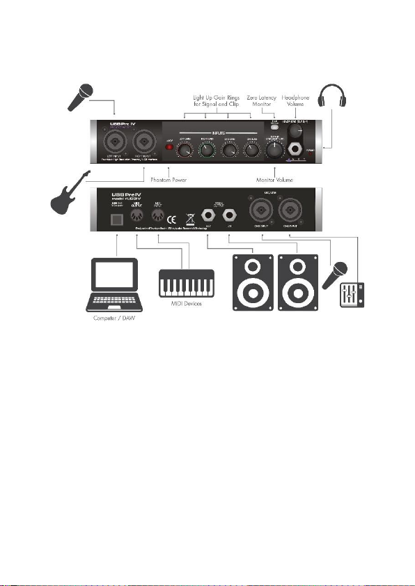
The Level Indicators around the channel gain pots respond to
incoming signals and the level applied. Adjust levels to get a
consistently green ring with occasional flashes of red. The red
ring indicates 2dB below digital clipping and should light on
musical peaks only. The green ring comes on about 10dB
before the red ring.
Outputs
The USB PRE IV is equipped with two pairs of stereo outputs.
Connect your studio monitors through the ¼-inch Main
Outputs (OUT1/2) on the rear panel using quality cables.
Headphones can be used for personal monitoring through the
stereo TRS Headphone jack (OUT3/4) on the front panel.
Press the Input Monitor button to listen to the signal directly
from the inputs. Otherwise, leave the Input Monitor off to
listen to the processed signal from the computer.
TIP: When using the Input Monitor function, reduce the level
on unused channels to reduce the noise in the output.
The Output Level (OUT1/2) control allows you to directly
adjust the Main Output rear jacks while the Headphone
(OUT3/4) control sets the level to the headphones.
Both the Main and Headphone outputs can be used to send
out different stereo feeds, which is handy when you want to run
to a mixer and instrument amp in a live situation, or when
connecting to a computer or recording system and locally
monitoring your source with headphones.

10
Headphone Setup
The USB Pre IV routes the Headphone (OUT3/4) signal on an
independent stereo path from the Main Outputs (OUT1/2). This
gives the user the flexibility of creating unique Main and
Headphone monitor mixes in their DAW of choice.
For listening to system sounds, user must select between the
Main Outputs and Headphone output as follows.
Windows 10
1. Click on the Windows home icon and type Sound
Settings into the search bar. Alternatively, click on
the speaker icon on the lower right side of your
screen.
2. To direct sound to the main outputs, select USB II
OUT1/2 or USBIV OUT1/2
3. To direct sound to the headphones, select USB II
OUT3/4 or USBIV OUT3/4
macOS 12.x (Monterey)
1. Open Audio MIDI Setup
2. Click ‘+’ in the lower left corner
3. Select ‘Create Aggregate Device’
4. Select USB IV or USB II
5. Apply labels to Output Channels 3 and 4 (i.e. name
them OUT3 and OUT4)
6. Click ‘Configure Speakers’
7. Choose OUT3 and OUT4 and click Apply
8. You can rename the Aggregate Device to USB IV
Headphones
9. Go to System Preferences > Sound

11
10. Select the ‘Aggregate Device’ you just created to
listen on OUT 3/4 or ‘USB IV Audio Interface’ to lis-
ten on OUT 1/2
macOS 11.x (Big Sur) and earlier
1. Open Audio MIDI Setup
2. USB IV Audio Interface > Output
3. Configure Speakers
4. Choose between Front Left,Front Right (OUT
1/2) or 3,4 (OUT 3/4)
5. Click Done

12
Creating a Headphone Out Bus in Cubase
1. Ensure you are using the USB II or USB IV ASIO driver
a. Go to Studio > Studio Setup
b. Set the ASIO Driver to USB II or USB IV de-
pending on your product
2. Create a headphone bus
a. Go to Studio > Audio Connections
b. Click Add Bus
c. Set the Bus Name to ‘Headphones’ and keep
the configuration of Stereo / L R
You can use the Headphones bus in two ways:
1. Set the output of your individual tracks to either ‘Stereo
Out’ (OUT1/2) or ‘Headphones’ (OUT3/4)
2. Create a Send on your track if you wish to monitor on both
‘Stereo Out’ and ‘Headphones’ simultaneously
a. On the track Inspector, go to Sends
b. Add a send to ‘Headphones’
c. Ensure the ‘Activate / Deactivate Send’ button is
set to Activate
USB
The USB connector provides power to the USB PRE IV while
delivering audio to and from your computer or mobile device.
The USB PRE IV is a USB 2.0 class compliant device. Use a
high-quality shielded USB cable for best performance and
avoid connections through USB hubs when possible.

13
ASIO Driver Configuration in Cubase
(Windows)
In order to take advantage of the low-latency ASIO driver
provided with the USB Pre IV, make the following adjustments
in Cubase.
1. Go to Studio > Studio Setup
2. Click Audio System
a. Select the USB II or USB IV from the ASIO
Driver pulldown on the right
b. Click Switch from the popup
3. Click USB II or USB IV on the left panel
a. Click Control Panel on the right side
b. Use the panel to select your desired sam-
pling rate and buffer size

14
MIDI
Input and Output
Use the MIDI INPUT and MIDI OUTPUT jacks to pass MIDI
data back and forth between your computer and devices such
as MIDI keyboard controllers, drum machines and sequencers.
The MIDI IN and MIDI OUT will show up as USB PRE IV under
your MIDI I/O selections.

15
Setup
The USB PRE II and USB PRE IV implement a USB-MIDI
interface to connect your instruments, sequencers and other
MIDI equipment to your computer.
Here is how the USB PRE IV’s MIDI presents itself in the
Windows 10 Device Manager:
Fig. 1 –Device Manager

16
When your Windows application wants to use the MIDI
interface, look for USB PRE II or USB PRE IV.
This is how the USB PRE IV MIDI I/O shows up on a MAC
using Audio/MIDI setup MIDI Window. As you can see there is
one input and one output that are not yet assigned.
Figure 2 –MAC Audio/MIDI setup, MIDI window

17
Using the MIDI I/O in Cubase
When you want to use the MIDI interface in Cubase, select the
Studio Setup function and then select the MIDI Port Setup.
Select USB PRE IV as seen in Fig. 3.
Fig. 3 –Cubase MIDI Port setup

18
Using the MIDI Device Manager, you can use the MIDI output
after installing a device and setting the output to USB PRE IV.
Once a MIDI output is assigned, it will show up as an output
selection on a MIDI track and Active in the MIDI Port Setup
window. Fig. 4 shows an example of assigning the USB PRE
IV MIDI output to a GM (General MIDI) device.
Fig. 4 –MIDI Device Manager

19
WARRANTY INFORMATION
Limited Warranty
Applied Research and Technology will provide warranty and
service for this unit in accordance with the following warrants:
Applied Research and Technology, (A R T) warrants to the
original purchaser that this product and the components thereof
will be free from defects in workmanship and materials for a
period of three years from the date of purchase. Applied
Research and Technology will, without charge, repair or
replace, at its option, defective product or component parts
upon prepaid delivery to the factory service department or
authorized service center, accompanied by proof of purchase
date in the form of a valid sales receipt.
This manual suits for next models
1
Table of contents
Other Art Accessories manuals
Popular Accessories manuals by other brands

Rockwell Automation
Rockwell Automation MagneMotion MagneMover LITE User manual addendum

Vinotemp
Vinotemp WINE-MATE WM-2500SSH-LA Operation Care Installation Manual

IKEA
IKEA KOPPLA 30362556 manual

Balluff
Balluff BVS ID-M1280-F1 Series Configuration guide

Omega Engineering
Omega Engineering CDE681 Series user manual

BEA
BEA IS40P user guide

Vertiv
Vertiv Liebert CRV300 Product documentation

Axor
Axor Uno 40088000 parts list

Smartwares
Smartwares SH4-99565AT-FR instruction manual

X-Rite
X-Rite DTP32HS Operator's manual

S+S Regeltechnik
S+S Regeltechnik THERMASGARD FSTM Operating Instructions, Mounting & Installation

Ametek
Ametek Solartron Metrology Orbit LTH manual