Art Project Series User manual


1
IMPORTANT SAFETY INSTRUCTION – READ FIRST
This symbol, whenever it appears alerts you to the presence
of uninsulated dangerous voltage inside the enclosure-
voltage that may be sufficient to constitute a risk of shock.
This symbol, whenever it appears, alerts you to important
operating and maintenance instructions in the
accompanying literature. Please read the manual.
Read Instructions: Retain safety and operating instructions for
future reference. Heed all warnings printed here and on the
equipment. Follow the operating instructions printed in this user
manual.
Do not open: There are no user serviceable parts inside. Refer
any service work to qualified technical personnel only.
Environment: Protect from excessive dirt, dust, heat, and vibra-
tion when operating and storing. Avoid tobacco ash, drink spill-
age and smoke, especially that associated with smoke ma-
chines.
Handling: Protect the controls from damage during transit. Use
adequate padding if you need to ship the unit. To avoid injury to
yourself or damage to the equipment, take care when lifting,
moving or carrying the unit.
Servicing: Refer servicing to qualified technical personnel.
Installation: Install the unit in accordance with the instructions
printed in the user manual.

2
INTRODUCTION
The USB Pre IV is a high quality 4 input / 4 output 192kHz capa-
ble digital interface for connecting a computer to a stereo or PA
system. It provides up to 4 mic inputs or two high Z instrument
and two-line inputs or any combination of these.
The USB Pre IV converts its four inputs with a 32-bit ADC with
sample rates from 44.1kHz to 192kHz for computer input. It con-
verts USB audio using a 32-bit quad DAC to analog
audio.
Knobs on the front panel of the USB Pre IV allow quick, precise
control over the Input gain, Headphone and Output level. The
front panel switch allows control over Phantom power.
Output Channels 3&4 are sent out through the headphone out-
put jack. This audio can be mixed with the input audio for low
latency monitoring through the headphone output.
The Sample rate is set via the USB interface and its low latency
ASIO/WDM driver. The USB Pre IV is powered from the USB
bus (cable Supplied).
The built-in low noise +48 Volt phantom power supply allows you
to power up to 4 microphones as well as the preamplifier.
For monitoring, an 1/4-inch TRS headphone jack with level and
monitor mix controls on the front allow for latency free local mon-
itoring of the inputs while recording as well as playback monitor-
ing of the USB bus. All four inputs are summed to MONO for the
monitor function. This summation is accomplished before being
summed with CH3&4.
The anodized all aluminum case is rugged and will handle a mul-
titude of environments. The USB Pre IV will provide you with
years of trouble-free service and its high-quality audio channels

3
are the obvious choice to entertain a wide variety of applications
from Podcasting/Broadcasting to tracking and monitoring.
With the USB Pre IV, your laptop, and a pair of quality micro-
phones you can do some serious remote recording.
The USB Pre IV is equipped with MIDI in and out, allowing com-
munication with other MIDI devices. This would allow for varies
types of sequencing and more.

4
Key Features Include
Four High-Quality 32-bit A to D Converters
Four High-Quality 32-bit D to A Converters
Sample rates from 44.1k to 192kHz
Low latency ASIO and WDM driver
Transformer isolated outputs
Low noise mic preamps
High Z instrument inputs
Zero latency monitoring
Front panel headphone output
MIDI Input
MIDI Output
Compact rugged package designed for years of use

5
Quick Startup Guide
Using the USB Pre IV with:
Windows PC:
Please log onto the artproaudio.com website.
Register your unit.
You will need to download the ASIO driver for this unit from the
ART website also.
USB PRE IV Driver:
To download the driver, you will need to log onto the artproau-
dio.com website. Download the driver from the support section
on the ART website (www.artproaudio.com).
MAC:
Please log onto the artproaudio.com website.
Register your unit.
There are no additional drivers needed.
Recording Software:
Please see the additional information sheet included, to access
this software download.

6
CONNECTIONS
A. Left and Right “Combo” jacks on the front allow for either
XLR or ¼-inch TRS input connections.
The connections are used for instrument or line level balanced
or unbalanced signals. The high fixed input impedance works
well with guitar and other passive instrument pickups. You can
use an unbalanced or balanced plug with this connection. The
XLR connections are used primarily for balanced microphone in-
puts.
Pin 2 is positive, pin 3 is negative, and pin 1 is ground.

7
B. +48V Switch: The +48 Volt phantom power (when ena-
bled) is supplied to pins 2 and 3 and pin 1 acts as the
ground return. Do not lift pin 1 when using phantom power.
C. INPUTS: These potentiometers independently vary the in-
put gain for the Left and Right Channels 1 thru 4.
D. OUTPUT LEVEL (OUT 1/2): This potentiometer varies the
output gain for channels 1 and 2.
E. Input Monitor: When the switch is engaged, a user can
monitor the input signal from the ¼-inch headphone jack.
F. Headphone LEVEL (OUT CH3/4): This potentiometer
allows the user to adjust the gain to the Headphone out
jack.
G. Headphone Jack: Access point for monitoring.
H. USB Jack: Interface and unit power.
I. MIDI INPUT/MIDI OUTPUT: Midi Access points.
J. Main Output: Analog outputs.
K. Left and Right “Combo” jacks on the rear allow for either
XLR or ¼-inch TRS input connections. You can use an un-
balanced or balanced plug with this connection.
CONTROLS and OPERATION
The ¼-inch output Jacks have an output impedance of 300
Ohms and a maximum output level of +8dBu (CH1/2) which pro-
vides a clean a signal for long cable runs. Normally you would
use this output to go directly into a power amplifier, powered

8
monitors, recording system, or a mixer’s balanced line or insert
inputs. Though we do not recommend it, if you have to go directly
into the balanced microphone input on a mixer make sure that
phantom power is off at the mixer. The mixer’s input pad and
level controls should be set for minimum gain, and the Monitor
Level control on the USB PRE IV should be set at a low enough
level to prevent overdriving the mixers input section.
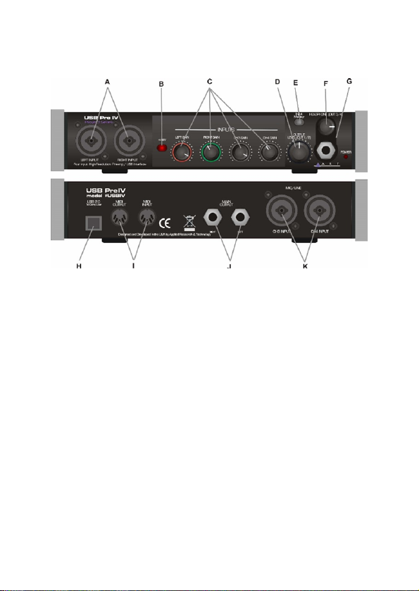
The 1/4-inch Headphone Monitor Output jack is stereo unbal-
anced TRS and has an output impedance of 32 Ohms. It can
accommodate a wide variety of headphone models. Maximum
output level is 60mW. You can use this as a second stereo line
output when not driving headphones.
Both the Main and Headphone outputs can be used to send out
different stereo feeds, which is handy when you want to run to a
mixer and instrument amp in a live situation, or when connecting
to a computer or recording system and locally monitoring your
source with headphones.
For a typical recording application where you want to add tracks
of audio using the USB bus to your computer while monitoring
the mix externally for low latency, we suggest the following: Con-
nect your instrument and/or microphone to the USB Pre IV in-
puts, then connect to your computer with a USB cable. Use the
1/4-inch Main output jacks to feed your powered monitors or an-
alog monitor system and use the 1/4-inch jack for local head-
phone monitoring by assigning audio to CH3/4 outputs. The new
track that you are recording will be in real time and have no la-
tency in your monitoring system.
The CH1 thru CH4 Gain Controls directly adjust the input ampli-
fiers giving you control over the dynamic range of your source.

9
You get from 0 to 50dB (Bal Inputs) of gain depending on set-
tings. Set the controls counterclockwise to minimum gain when
connecting the inputs.
The Output Gain control allows you to directly adjust the CH1/2
rear jacks.
The Input Monitor switch when engaged, feeds the audio to the
Headphone CH3/4 jack. The Input Monitor function sums all of
the input channels into mono and sends this audio to the Head-
phone out. When this function is used minimize the unused
channels, this will reduce the noise in the output. The headphone
gain can be adjusted from the Headphone Level (3/4CH) pot.
You can use the headphone output as an unbalanced line level
signal source when not using it for monitoring with headphones.
The Phantom power switch on the front, applies +48 Volt phan-
tom power to the XLR input jacks for powering microphones, if
needed. It is slow at turning on and off and is current limited to
protect sensitive microphones and reduce audible pops. Ideally,
when connecting a microphone that requires phantom power,
you should first turn down gain. Next connect the microphone,
switch on the phantom power and bring the gain back up to the
desired level. This minimizes pops in your system and stress on
the microphone.
The USB bus will power the USB Pre IV interface. When used in
a portable or remote recording situation the USB Pre IV, a laptop
computer, a pair of microphones, and a set of headphones, be-
come your entire system.
The Level Indicators are shown through LED light rings around
the channel gain pots. When monitoring the Signal Level dual
function LED ring metering circuitry around the gain pots on each
channel aids in setting gain and has a fast attack to help indicate

10
any clipping. The metering is located in the signal chain just after
the preamp circuitry to help in setting signal levels going to your
computer. The monitor controls come after the metering so that
you can use the meters to set the overall input gain on each
channel for best recording dynamic range and then trim the Mon-
itor Mix and Level to the monitor system you are driving. The red
“Clip indicator” ring displays a red color just before clipping (2dB
before digital clipping and 6dB before analog clipping) and
should light on musical peaks only. The green “signal indicator”
comes on around 10dB before the “Clip indicator” and indicates
how far below clipping your signal is. The “signal indicator ring”
has a longer release time and should be on much of the time
during performance and if not, it indicates that your signal or in-
put gain may be too low for best results.

11
MIDI IN AND OUT
When setting up an external device with your USB Pre IV, you
can configure MIDI Modules and controllers. These MIDI con-
nections allow this unit to communicate with other MIDI con-
trolled devices. Please reference the manufacturer’s manual for
the complete installation instructions of the MIDI device you
would like to interface with the USB Pre IV. The MIDI IN and
MIDI OUT will show up as USB IV under your MIDI I/O selec-
tions.

12
MIDI SETUP
The USB Pre II and USB Pre IV implements a USB-MIDI inter-
face to connect your instruments, sequencers and other MIDI
equipment to your computer.
Here is how the USB Pre II’s MIDI presents itself in Win 10’s
Device Manager:
Fig. 1 – Device Manager

13
When your Windows application wants to use the MIDI interface,
look for USB II or USB IV.
This is how the USB Pre II MIDI I/O shows up on a MAC using
Audio/MIDI setup MIDI Window. As you can see there is one in-
put and one output that are not yet assigned.
Figure 2 – MAC Audio/MIDI setup, MIDI window

14
Using the MIDI I/O in Cubase.
When you want to use the MIDI interface in Cubase, select the
Studio Setup function and then select the MIDI Port Setup. Se-
lect USB II (USB IV) as seen in Fig. 3.
Fig. 3 – Cubase MIDI Port setup
Using the MIDI Device Manager, you can use the MIDI output
after installing a device and setting the output to USB IV.

15
Once a MIDI output is assigned, it will show up as an output se-
lection on a MIDI track and Active in the MIDI Port Setup win-
dow. Fig. 4 shows an example of assigning the USB Pre II (IV)
MIDI output to a GM (General MIDI) device.
Fig. 4 – MIDI Device Manager

16
Brief notes
Does Cubase (MAC) work the same? (Yes! Works and Looks
Identical). Therefore, we only need Cubase an example of ap-
plying the MIDI I/O for both machines (not requiring a Garage
Band sample and saving space).
Once in a while a customer will call and say: I think my ART pre-
amp is "noisy". What's wrong?
If you experience unwanted "noise" in your system when you use
a stand-alone preamp, please consider what your signal is and
where you're sending it. Some people send the signal from their
preamp to a mic input (they figure, "well, I'm using a mic!") on the
board or recorder. This is in fact incorrect and could create
higher overall noise. ART preamps are actually intended to out-
put a nice fat LINE LEVEL signal. If you send that line level signal
to a recorder or mixer's Mic input, that circuit will usually add
more gain to the signal. Gain on top of gain will indeed result in
noise. Please treat the output signal as line level and you'll be
pleasantly surprised at your new clean and warm sound.
The same rule applies for guitar and bass players that use ART
preamps as their front end. Send the signal from your preamp to
a low gain input on your amp, or even a "loop return" jack which
allows you to bypass the amp's solid-state preamp altogether.
Another point: an "open" input is significantly noisier than one
that has a mic or even a guitar plugged in.

17
USB OPERATION
Connect your analog jacks. If you are using one of the analog
MONITOR outputs for local low latency monitoring, connect that
to your monitor system or headphones. Next, set the front panel
controls for proper operation as per the previous sections. Then
connect the USB cable to the appropriate input on your computer
and lastly to the USB connector on the USB Pre IV.
Once the USB connection is made and your computer is on, the
unit will automatically connect and try to set your computer “De-
fault Audio Device” to be “USB IV”. The same settings may need
to be made in your particular audio application as well (check
your application instructions). These settings should be made
while the USB Pre IV and computer are connected and powered
on.
Your computer audio output “Speaker” is now set to be the (USB
IV 1/2) or (USB IV 3/4) and playback audio is routed to the USB
Pre IV. This must be done while the USB Pre IV is connected to
the computer and powered on. If you prefer, you can have the
computer output routed to your computer speakers instead of the
USB Pre IV monitor output jack, by selecting your computer
speakers for “OUTPUT” instead of “USB IV” in the above setup
procedures. After the above settings are made, your computer
will automatically reconfigure itself back to these settings every
time the USB Pre IV is reconnected to the computer. Your re-
cording software may also select which inputs or outputs are be-
ing used.
At this point your recording software will select and control which
channels are being recorded and which channels are being mon-
itored. There are many computer recording software packages
available today that allow for multi-track recording.
Latency, the time delay between your audio input and the USB
output to your computer, is very short depending on the speed
of your computer. The latency of your system may be tweaked

18
using the control panel. Typically, on a Mac, the core audio in-
terface has low latency so this is usually not an issue.
ART provides a low latency driver, which you need to download
from our website to use the unit with windows. This is an ASIO
driver, so your application needs to use ASIO I/O to take ad-
vantage of this driver and its control panel.

19
APPLICATIONS
Microphone Pre-Amplifier
The USB Pre IV can be used as a high-quality microphone pre-
amplifier suitable for all dynamic, condenser, and ribbon micro-
phones. Most conventional mixers utilize budget minded micro-
phone preamps and while very functional, they do not sound all
that great. The USB Pre IV serves as a quality upgrade that will
give you more flexibility and a more robust tone than standard
mixer preamps.
Simply plug a microphone into the XLR input. Apply phantom
power if using a condenser. Then dial up the gain and you are
Other manuals for Project Series
6
This manual suits for next models
2
Table of contents
Other Art Accessories manuals
Popular Accessories manuals by other brands

Spinshot
Spinshot SPINSHOT plus owner's manual

Hytronik
Hytronik HEC9025/I Installation and instruction manual

Borotto
Borotto Lumia 8 instruction manual

Gutta
Gutta ECO 120 Assembly instructions

TEKTELIC Communications
TEKTELIC Communications Kona All-in-One Home Sensor user guide

Gifas-electric
Gifas-electric 1970W user manual