ART2WAVE ap20 User manual

AP20 Installation Guide
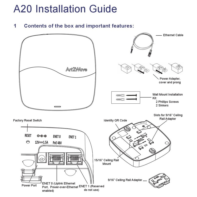
1 Contents of the box and important features:
Factory Reset Switch
Power Port ENET 0 (Uplink Ethernet
Port, Power-over-Ethernet
enabled)
ENET 1 (Reserved
do not use)
9/16” Ceiling Rail Adapter
15/16” Ceiling Rail
Mount
Identity QR Code
Slots for 9/16” Ceiling
Rail Adapter
Ethernet Cable
Power Adapter,
cover and prong
Wall Mount Installation
Kit:
2 Phillips Screws
2 Sinkers

5 Mounting the Access Point
Note: Do not mount the access point until it is linked to your Art2Wave account.
You can mount the AP20 in the following ways:
• Ceiling mounting (with 15/16” or 9/16” rails)
• Wall mounting
• Desk mounting
2 Setting up your AP20 Access Point
3 Linking the Access Point to your Art2Wave account
3.1 Using your mobile device
3.2 Using the Website
4 Connecting the Access Point to your network and power supply
There are four steps to setting up an AP20 access point:
1. Linking the access point to your Art2Wave account
2. Connecting the access point to your network and power supply
3. Mounting the access point
4. Verifying connectivity
There are two ways to link your access point to your account: using your mobile device or using
the Art2Wave website.
By installing the Art2Wave mobile device app, you can scan the QR code on the back of the
access point and link it to your account. Information about the app is available at
http://art2wave.com. The mobile device app includes instructions for completing the process.
To link the access point to your account using the Website, sign into your account at
http://art2wave.com and follow the instructions in the Art2Wave web site to complete the
process.
Connect the access point to your network by plugging an Ethernet cable into the ENET 0 port.
Do not connect to the ENET 1 port (this port is reserved for future use).
The Access point is powered either by connecting the supplied power adapter to an AC wall
outlet or by connecting the ENET 0 port to a device that provides 802.3af Power-over-
Ethernet. If using the supplied power adapter, remove the cover and insert the prong as shown
in Section 1.

5.1 Tips for selecting a location
The best location for your access point is at the center of your wireless coverage area, within
line of sight of all wireless devices. To get the best performance, consider the following:
• Mount the access point as high as possible above any obstructions
• Do not mount the access point next to building support columns or any other
physical obstructions that may cause dead zones
• Do not mount the access point near any material that may absorb or reflect Wi-Fi
signals
This unit must be installed indoors. The unit, AC power adapter, and its
cables are not designed for outdoor use.
Warning

The figure below shows you how to clip the access point to a 15/16” ceiling rail. Printed
instructions on the back of the unit explain which clips to use.
5.2 Ceiling mounting to a 15/16” rail
Slide the Access point diagonally
over the rail and rotate until the
unit clicks into place.
Press thess clips in and turn to
dismount the Access Point

5.3 Ceiling mounting to a 9/16” rail
The figure below shows you how to use the adapter to clip the access point to a 9/16” ceiling
rail. Printed instructions on the back of the unit explain which clips to use.
1. Slide the adapter
into the clips on the
back on the unit.
2. With the adapter in place,
slide the Access Point
diagonally over the rail and
rotate until the unit clicks into
place.
Press these clips and turn to
dismount the Access Point

5.4 Wall mounting
The figure below shows you how to mount the access point to a wall using screws and sinkers.
Note: Screw center distance = 141mm.

6 Verifying connectivity
7 Tips and Troubleshooting
7.1 If your access point status light is flashing yellow
You can verify that the AP20 Access point is connected to your network by using either the
Art2Wave website, or mobile device app that you used to link the unit to your Account.
Check the Status LED to determine whether the access point is operating correctly. The
access point is properly installed and connected to the Art2Wave management services when
the LED turns solid blue after a few minutes.
When the access point is powered on, the Status LED should display the following sequence:
The access point cannot connect to the Art2Wave management services. This usually occurs
when the unit cannot get an IP Address from your network using DHCP and has switched to
Local Network Configuration mode.
Note: See the Tips and Troubleshooting section if the access point does not reach Solid blue.
For a full description of LED Status Description visit the Support website
(www.art2wave.com/support).
Unit has just received power and has started
booting
Solid red
(for less than 5 seconds)
Solid Yellow
(for less than a minute)
Blinking blue
(for less than a minute)
Solid blue
Unit is starting up. Or if the Factory Reset
switch has been pressed, the unit is
resetting to factory condition.
Access point is negotiating a connection
with Art2Wave management services in the
cloud.
Access point is successfully set up to be
managed by Art2Wave management
services in the cloud.
Status Description# LED
1
2
3
4

8 Learning More, Service, and Support
8.1 Online Resources
7.2 Resetting back to factory defaults
While in this mode, the access point will not pass data through the ENET 0 port and will
broadcast an SSID that contains a portion of the access point’s MAC Address. You can use
any Wi-Fi enabled device to connect to this SSID and configure the network settings for this
access point using a web browser
To connect to the access point using the Local Network Configuration interface:
1. Connect your Wi-Fi enabled device to the SSID in the form of “AP-XX:XX:XX” (where
X is a placeholder). You are successfully connected when the LED on the Access
Point becomes solid purple
2. Use your web browser to navigate to http://192.168.100.1
3. Follow the on-screen instructions
See the Support section (http://art2wave.com/support) for information about Local Network
Configuration.
Note: Local Configuration mode will only activate if the access point is in Factory Default
condition and has never connected to the Art2Wave management services in the cloud.
If the access point is disconnected from a power source, press and hold the reset button, and
connect power to the unit. The LED will turn solid white to indicate the unit is restoring itself to
Factory Defaults.
OR
If the access point is connected to a power source, press and hold the reset button until the
LED turns solid white and then release. This will restore the unit to the factory default settings.
Our support website (http://art2wave.com/support) contains links to online resources available
to help you get the most out of your access point.

9 Legal Notice
EXCEPT FOR ANY WRITTEN EXPRESS WARRANTY WE MAY SEPARATELY OFFER TO YOU,
AND TO THE EXTENT PERMITTED BY LAW, THIS PRODUCT IS PROVIDED “AS IS” AND WE
SPECIFICALLY DISCLAIM ALL EXPRESS, STATUTORY AND IMPLIED WARRANTIES,
INCLUDING, BUT NOT LIMITED TO, WARRANTIES OF MERCHANTABILITY, FITNESS FOR A
PARTICULAR PURPOSE, NON-INFRINGEMENT AND AGAINST HIDDEN OR LATENT
DEFECTS. IF WE CANNOT LAWFULLY DISCLAIM STATUTORY OR IMPLIED WARRANTIES,
THEN TO THE EXTENT PERMITTED BY LAW, ALL SUCH WARRANTIES SHALL BE LIMITED
IN DURATION TO THE DURATION OF ANY WRITTEN EXPRESS WARRANTY WE MAY
SEPARATELY OFFER TO YOU, AS APPLICABLE, AND TO REPAIR OR REPLACEMENT
SERVICE. SOME JURISDICTIONS DO NOT ALLOW LIMITATIONS ON HOW LONG A
STATUTORY OR IMPLIED WARRANTY LASTS, SO THE ABOVE LIMITATION MAY NOT
APPLY TO YOU. WE ARE NOT RESPONSIBLE FOR DIRECT, SPECIAL, INCIDENTAL OR
CONSEQUENTIAL DAMAGES RESULTING FROM ANY BREACH OF WARRANTY OR UNDER
ANY OTHER LEGAL THEORY. IN SOME JURISDICTIONS THE FOREGOING LIMITATION
DOES NOT APPLY TO DEATH OR PERSONAL INJURY CLAIMS, OR ANY STATUTORY
LIABILITY FOR INTENTIONAL AND GROSS NEGLIGENT ACTS AND/OR OMISSIONS, SO THE
ABOVE EXCLUSION OR LIMITATION MAY NOT APPLY TO YOU. SOME JURISDICTIONS DO
NOT ALLOW THE EXCLUSION OR LIMITATION OF DIRECT, INCIDENTAL OR
CONSEQUENTIAL DAMAGES, SO THE ABOVE EXCLUSION OR LIMITATION MAY NOT
APPLY TO YOU.
8.2 Copyright and Trademark
Copyright © 2015 Art2Wave, Inc. All rights reserved. The contents of this Installation Guide are
the copyrighted and proprietary property of Art2Wave, Inc. Reproduction, distribution or
modification without the express, written permission of Art2Wave, Inc. is not permitted.
“Art2Wave” is a trademark of Art2Wave, Inc. All other trademarks are the property of their
respective owners.
8.3 Open Source Code
Certain Art2Wave products include open source software code subject to the GNU General
Public License (GPL) and other Open Source Licenses. For more information, see:
http://art2wave.com/opensource

11.1 FCC
10 AP20 Specifications and Safety Guidelines
11 Regulatory Compliance Information
Specifications:
Frequency Band: 2.4GHz and 5GHz
Standards: 802.11a, 802.11b, 802.11g, 802.1n, and 802.11ac specifications
Interfaces:
1 RJ-45 10/100/1000Base-T Gigabit Ethernet Uplink with 802.3af Power-over-Ethernet (PoE)
support (15.4W)
1 RJ-45 10/100/1000Base-T Gigabit Ethernet LAN
Simultaneous dual-band 802.11ac Wi-Fi
Environmental Specifications:
Operating Temperature: 0 to 40℃
Storage Temperature: -40 to 80℃
Relative Humidify (Operational): 10 to 90% RH (non-condensing)
Relative Humidity (Storage): 5 to 95% RH (non-condensing)
This equipment has been tested and found to comply with the limits for a Class B digital
device, pursuant to Part 15 of the FCC Rules. These limits are designed to provide reasonable
protection against harmful interference in a residential installation. This equipment generates,
uses and can radiate radio frequency energy and, if not installed and used in accordance with
the instructions, may cause harmful interference to radio communications. However, there is
no guarantee that interference will not occur in a particular installation. If this equipment does
cause harmful interference to radio or television reception, which can be determined by turning
the equipment off and on, the user is encouraged to try to correct the interference by one of
the following measures:
• Reorient or relocate the receiving antenna
• Increase the separation between the equipment and receiver
• Connect the equipment into an outlet on a circuit different from that to which the
receiver is connected
• Consult the dealer or an experienced radio/TV technician for help
FCC Caution: Any changes or modifications not expressly approved by the party responsible
for compliance could void the user's authority to operate this equipment. See 47 CFR 1.80.

This device complies with Part 15 of the FCC Rules. Operation is subject to the following two
conditions: (1) This device may not cause harmful interference, and (2) this device must accept
any interference received, including interference that may cause undesired operation.
IMPORTANT NOTE:
Radiation Exposure Statement:
This equipment complies with FCC radiation exposure limits set forth for an uncontrolled
environment. This equipment should be installed and operated with minimum distance 20cm
between the radiator & your body.
This transmitter must not be co-located or operating in conjunction with any other antenna or
transmitter.
Regulatory domain cannot be altered for US/CANADA products.
Operation of this device is restricted to indoor use only.
11.2 Industry Canada
This device complies with Industry Canada’s licence-exempt RSSs. Operation is subject to the
following two conditions:
(1) This device may not cause interference; and (2) This device must accept any interference,
including interference that may cause undesired operation of the device.
Cet appareil est conforme aux CNR exemptes de licence d'Industrie Canada. Son
fonctionnement est soumis aux deux conditions suivantes:
(1) Ce dispositif ne peut causer d'interférences; et(2) Ce dispositif doit accepter toute
interférence, y compris les interférences qui peuvent causer un mauvais fonctionnement de
l'appareil.
Caution:
(i) the device for operation in the band 5150-5250 MHz is only for indoor use to reduce the
potential for harmful interference to co-channel mobile satellite systems;
(ii) the maximum antenna gain permitted for devices in the bands 5250-5350 MHz and 5470-
5725 MHz shall comply with the e.i.r.p. limit; and
(iii) the maximum antenna gain permitted for devices in the band 5725-5825 MHz shall comply
with the e.i.r.p. limits specified for point-to-point and non point-to-point operation as
appropriate.

ICES-003 issue 5(2013/08/01)
CAN ICES-3(*)/NMB-3(*)
[*] = Class A or B
(iv) Users should also be advised that high-power radars are allocated as primary users (i.e.
priority users) of the bands 5250-5350 MHz and 5650-5850 MHz and that these radars could
cause interference and/or damage to LE-LAN devices.
Avertissement:
(i) les dispositifs fonctionnant dans la bande 5150-5250 MHz sont réservés uniquement pour
une utilisation à l’intérieur afin de réduire les risques de brouillage préjudiciable aux systèmes
de satellites mobiles utilisant les mêmes canaux;
(ii) le gain maximal d’antenne permis pour les dispositifs utilisant les bandes 5 250-5 350 MHz
et 5 470-5 725 MHz doit se conformer à la limite de p.i.r.e.;
(iii) le gain maximal d’antenne permis (pour les dispositifs utilisant la bande 5 725-5 825 MHz)
doit se conformer à la limite de p.i.r.e. spécifiée pour l’exploitation point à point et non point à
point, selon le cas.
(iv) De plus, les utilisateurs devraient aussi être avisés que les utilisateurs de radars de haute
puissance sont désignés utilisateurs principaux (c.-à-d., qu’ils ont la priorité) pour les bandes 5
250-5 350 MHz et 5 650-5 850 MHz et que ces radars pourraient causer du brouillage et/ou
des dommages aux dispositifs LAN-EL.
Radiation Exposure Statement:
This equipment complies with IC radiation exposure limits set forth for an uncontrolled
environment. This equipment should be installed and operated with minimum distance 20cm
between the radiator & your body.
Déclaration d'exposition aux radiations:
Cet équipement est conforme aux limites d'exposition aux rayonnements IC établies pour un
environnement non contrôlé. Cet équipement doit être installé et utilisé avec un minimum de
20 cm de distance entre la source de rayonnement et votre corps.
R
2002/95/EC
COMPLIANT
oHS
5018095201
Table of contents
Other ART2WAVE Wireless Access Point manuals
Popular Wireless Access Point manuals by other brands

Ruijie
Ruijie RG-AP810-L Hardware installation and reference guide

NODEXON
NODEXON NX-AP8000 Series Product guide

Alcatel-Lucent
Alcatel-Lucent OAW-AP210 Series installation guide

ALCON
ALCON ACP24 user manual

Moxa Technologies
Moxa Technologies AirWorks AWK-3121-M12-RTG Quick installation guide

Alcatel-Lucent
Alcatel-Lucent 9764 Series Operation and installation