manuals.online logo
Brands
  1. Home
  2. •
  3. Brands
  4. •
  5. Rutenbeck
  6. •
  7. Wireless Access Point
  8. •
  9. Rutenbeck AC WLAN UAE Up User manual

Rutenbeck AC WLAN UAE Up User manual

AC WLAN
Kurzbedienungsanleitung/Quick Guide
Safety Instructions
Electrial power supply!
Hazardous to life and fire danger due to electrical voltage
of 230 V!
- Work on the 230-V-supply may only be carried out by authorized electricians!
- Disconnect the main voltage before installation work!
Intended Use
This device has three operating modes. It can be used as an Accesspoint
for wireless communicating devices or as a repeater which increases the
distance of the WLAN network.
Furthermore, it can be connected to devices, which do not have an own
WLAN adapter.
Only use this device for these purposes and operate indoors.
General
The AC WLAN extends the use of modern mobile network technologies
with low power consumption and low-radiation emisson.
With the function settings you optimize the demarcation among individual
Accesspoints and avoid overcouplings of the wireless areas and losses of
data rates.
Detailed user information can be found at www.rutenbeck.de.
Installation
Connection of Power Supply
Warning! Hazardous for life! Disconnect the main voltage before
connection.
The standard five safety rules according to DIN VDE
0105 apply:
1 Disconnect from the power supply
2 Secure against reconnection
3 Check that equipment is dead
4 Earth and short circuit
5 Cover or screen off all live adjacent parts
Connect the mains voltage to the screw terminals L
and N.
In order to avoid interference of the network by distur-
bances/alterations in the range of the 230-V-installation
please always disconnect the power supply of the active
devices as AC WLAN of those of other power consumers
(e. g. microwave, vacuum cleaner, radio).
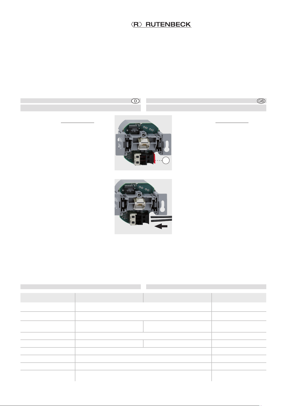
Use a separate circuit e. g. by applying a line-protective
or line disconnecting switch (figure, A) or an insulated overvoltage protec-
tion (C-arrester) and clearly label the circuit as well as the belonging jacks
clearly, e. g. with “EDP”.
Connection of network cable to the screw terminal block
1 Pull the cable preferably from top of the installation box
(figure, B).
2 Shorten the cable so that approx. 90 mm remain from the
installation box bottom.
3 Strip off the cable sheath to approx. 80 mm.
4 Pull off the 5-pole terminal block and connect the wires
according to the color code below.
VLeave the wire pair shielding and the wire twist for
as long as possible!
VTwist the shielding (S) and, if necessary, use a
1 mm wire end sleeve.
VMake sure the wires are connected according to
the color code in the patch panel and on the jack!
5 Put the terminal block on the screw terminal block.
Sicherheitshinweise
Elektrische Spannung!
Lebensgefahr und Brandgefahr durch elektrische Spannung
von 230V möglich.
- Arbeiten am 230-V-Netz dürfen nur durch Elektrofachpersonal ausgeführt
werden!
- Vor Montage/Demontage Netzspannung freischalten!
Bestimmungsgemäßer Gebrauch
Dieses Gerät hat drei Betriebsarten. Es kann entweder als Zugangspunkt
(Accesspoint) für drahtlos kommunizierende Geräte verwendet werden
oder als Repeater die Reichweite im WLAN-Netzwerk erhöhen. Darüberhi-
naus kann es an Geräte angeschlossen werden, die über keinen eigenen
WLAN-Adapter verfügen.
Benutzen Sie das Gerät zu keinem anderen Zweck. Betreiben Sie das
Gerät nur in Innenräumen.
Allgemeines
Der AC WLAN erweitert die Nutzungsmöglichkeiten moderner, mobiler
Netzwerktechnologien bei geringer Leistungsaufnahme und strahlungsar-
mer Funkemission.
Mit den Funktionseinstellungen optimieren Sie die Abgrenzung unter ein-
zelnen Accesspoints und vermeiden Überkopplungen der WLAN-Bereiche
und Einbußen bei den Datenraten.
Ausführliche Benutzerinformationen finden Sie unter www.rutenbeck.de.
Installation
Anschließen der Netzspannung
Lebensgefahr! Schalten Sie die Netzspannung vor dem
Anschließen frei.
Beachten Sie bei Arbeiten in und an elektrischen Anlagen
die fünf Sicherheitsregeln nach DIN VDE 0105:
1 Freischalten
2 Gegen Wiedereinschalten sichern
3 Spannungsfreiheit allpolig feststellen
4 Erden und Kurzschließen
5 Benachbarte unter Spannung stehende Teile
abdecken.
Schließen Sie die Netzspannung an die Klemmen L und N an.
Um eine Beeinflussung des Netzwerks durch Störun-
gen/Veränderungen im Bereich der 230-V-Installation zu
vermeiden, trennen Sie stets die Spannungsversorgung
aktiver Komponenten sowie der Datenendgeräte (PC
usw.) von denen anderer Verbraucher (z. B. Mikrowelle,
Staubsauger, Radio).
Verwenden Sie eigene Stromkreise, indem Sie z. B. einen Leitungstrenn-
oder -schutzschalter (Bild, A) einsetzen und ggf. einen geeigneten Über-
spannungsschutz (C-Ableiter). Kennzeichnen Sie den Stromkreis sowie die
zugehörigen Steckdosen eindeutig, z. B. mit „EDV“.
Anschließen des Netzwerk-Kabels an die Schraubklemmleiste
1 Ziehen Sie das Kabel vorzugsweise oben in die Einbaudo-
se ein (Bild, B).
2 Kürzen Sie das Kabel so, dass ca. 90 mm vom Dosenbo-
den an verbleiben.
3 Isolieren Sie das Kabel auf ca. 80 mm ab.
4 Ziehen Sie den 5-poligen Schraubklemmblock ab und
legen Sie die Adern nach untenstehendem Farbcode
auf.
VErhalten Sie die Paarschirmung und die Verdril-
lung der Paare so lang wie möglich!
VVerdrillen Sie den Gesamtschirm (S) und verwen-
den Sie ggf. eine 1-mm-Aderendhülse.
VBeachten Sie die gleiche Belegung im Rangierfeld
und an der Dose!
5 Setzen Sie den Klemmblock auf die Schraubklemme.
6 3 2 1
Farbcode
Klemme
Belegung
6 3 2 1
Color code
Terminal
Assignment
L
N
B
A
© Wilhelm Rutenbeck GmbH & Co. KG · 293 721 (10522301) · Technische Änderungen vorbehalten/Subjected to technical changes · Stand/Status 05.13
Niederworth 1-10
58579 Schalksmühle
Telefon +49-(0) 23 55-82-0
Telefax +49-(0) 23 55-82-105
www.rutenbeck.de
[email protected]
AC WLAN UAE Up AC WLAN POF/UAE 1xUp 2,2 mm
Schutzart IP20 gemäß/according to DIN EN 60529 Protection Class
Betriebstemperatur -5 °C – 45 °C Operating temperature
Anschlüsse RJ 45 (10/100 Mbit/s)
Schraubkontakte/screw terminals
RJ 45 (10/100 Mbit/s)
2,2 mm Duplex POF Connections
Spannungsversorgung 100-240 V~/50-60 Hz Power supply
Leistungsaufnahme 1,8 W  2,5 W Power consumption
Funkbereich 2,4 GHz Wireless range
Funkdatenraten 150 Mbit/s Wireless data rates
Funkstandard IEEE 802.11 b/g/n Wireless standard
Sicherheit/
Verschlüsselung WEP, WPA, WPA2 Security/encryption
Zuschneiden und Anschließen des POF-Kabels
Nach dem Verlegen des POF-Kabels (Hinweise
hierzu finden Sie unter www.rutenbeck.de im
Downloadbereich) gehen Sie folgendermaßen vor:
1 Ziehen Sie das Kabel in die Schalter- oder
Kanaleinbaudose ein und kürzen Sie die Leiter
auf ca. 190 mm.
Verwenden Sie ausschließlich Geräte-Verbin-
dungsdosen!
2 Trennen Sie das Kabel in der Mitte ca. 30 mm
vorsichtig auf und achten Sie darauf, dass kei-
ne Unebenheiten des Mantels das Einführen
des Kabels behindern können.
3 Führen Sie es in das POF-Schneidewerkzeug
ein und schneiden Sie es durch Druck auf die
Klinge ab.
4 Achten Sie darauf, dass beide Adern gleich
lang sind.
5 Öffnen Sie die POF-Klemme durch leichtes
Ziehen am schwarzen Anschluss und entfernen
Sie die rote Schutzkappe (C).
6 Führen Sie das POF-Kabel ein (Bild, Pfeil) und
achten Sie darauf, dass es bis zum Anschlag
geschoben wird, um eine sichere Verbindung
zu gewährleisten.
7 Schließen Sie die POF-Klemme, indem Sie den
schwarzen Anschluss zum Fixieren des Kabels
in die Geräteöffnung schieben.
Der AC WLAN ist nun mit den Werkseinstellungen betriebsbereit.
Für individuelle Einstellungen verbinden Sie nun den AC WLAN über
ein Patchkabel mit der LAN-Schnittstelle Ihres PCs und konfigurieren
Sie ihn nach Ihren Wünschen.
Sie erreichen ihn unter der IP-Adresse http://192.168.0.5
Password: admin (WLAN SSID: Rutenbeck / Key: wireless123)
(Werkseinstellung).
Technische Daten
Installation Installation
Cutting and connecting the POF-cable
After the POF-cable is laid (corresponding hints
can be found under www.rutenbeck.de in the
dowload-sector) follow as described below:
1 Pull the cable through the installation box and
shorten the fibres to approx. 190 mm.
Only use junction-boxes!
2 Carefully split the cable down the middle for
approx. 30 mm and make sure that there is no
unevenness on the coating which could hinder
the inserting of the cable.
3 Insert the cable into the POF cutting tool and cut
it by pressing the blade.
4 Make sure that both wires are equally long.
5 Open the POF terminal by slightly pulling it out
and remove the red protection cap (C).
6 Insert the POF-cable (figure, arrow). Make sure
that it is pushed all the way up to the stop in
order to guarantee a safe connection.
7 Close the POF terminal by pushing it into the
opening of the device to fasten the cable.
Now the AC WLAN with the default settings is ready for operation.
For individual settings connect the AC WLAN via patch cable with
the LAN interface of your PCs and set up according to your wishes.
By entering the IP address http://192.168.0.5 in the browser the
AC WLAN can be reached.
Password: admin (WLAN SSID: Rutenbeck / Key: wireless123)
(default settings).
Technical Data
C

This manual suits for next models

1

Other Rutenbeck Wireless Access Point manuals

Rutenbeck Up-Accesspoint UAE PoE 2,4 GHz 300M rw User manual

Rutenbeck

Rutenbeck Up-Accesspoint UAE PoE 2,4 GHz 300M rw User manual

Rutenbeck Up-Accesspoint UAE 2,4GHz 300M rw User manual

Rutenbeck

Rutenbeck Up-Accesspoint UAE 2,4GHz 300M rw User manual

Rutenbeck AC WLAN Series User manual

Rutenbeck

Rutenbeck AC WLAN Series User manual

Rutenbeck AC WLAN UAE/USB User manual

Rutenbeck

Rutenbeck AC WLAN UAE/USB User manual

Rutenbeck AC WLAN Up rw User manual

Rutenbeck

Rutenbeck AC WLAN Up rw User manual

Rutenbeck 226104031 User manual

Rutenbeck

Rutenbeck 226104031 User manual

Popular Wireless Access Point manuals by other brands

TRENDnet TEW-510APB Specifications

TRENDnet

TRENDnet TEW-510APB Specifications

4IPNET OWL800 user manual

4IPNET

4IPNET OWL800 user manual

Zonet ZEW3002 user manual

Zonet

Zonet ZEW3002 user manual

D-Link DAP-1150 Quick installation guide

D-Link

D-Link DAP-1150 Quick installation guide

Advantech EKI-6333AC-A Series user manual

Advantech

Advantech EKI-6333AC-A Series user manual

Motorola AP 7161 installation guide

Motorola

Motorola AP 7161 installation guide

Ubiquiti AF-2X user guide

Ubiquiti

Ubiquiti AF-2X user guide

NETGEAR WG302v2 - ProSafe 802.11g Wireless Access... Reference manual

NETGEAR

NETGEAR WG302v2 - ProSafe 802.11g Wireless Access... Reference manual

TP-Link Omada EAP225-Wall Quick installation guide

TP-Link

TP-Link Omada EAP225-Wall Quick installation guide

Aruba Instant On AP15 installation guide

Aruba

Aruba Instant On AP15 installation guide

Vonets VAP11N Quick setting guide

Vonets

Vonets VAP11N Quick setting guide

Aerohive HiveAP 100 Series quick start

Aerohive

Aerohive HiveAP 100 Series quick start

Ruijie RG-AP680 CD Series Hardware  installation and reference guide

Ruijie

Ruijie RG-AP680 CD Series Hardware installation and reference guide

PROLiNK WNR1004 Quick installation guide

PROLiNK

PROLiNK WNR1004 Quick installation guide

TP-Link Auranet EAP120 installation guide

TP-Link

TP-Link Auranet EAP120 installation guide

TP-Link Auranet EAP110 installation guide

TP-Link

TP-Link Auranet EAP110 installation guide

Proxim ORiNOCO AP-700 user guide

Proxim

Proxim ORiNOCO AP-700 user guide

Asus WL 320gE - Wireless Access Point user manual

Asus

Asus WL 320gE - Wireless Access Point user manual

manuals.online logo
manuals.online logoBrands
  • About & Mission
  • Contact us
  • Privacy Policy
  • Terms and Conditions

Copyright 2025 Manuals.Online. All Rights Reserved.