Artec Group Broadway 3D B User manual

Broadway 3D Security System
USER MANUAL
v.1.1.0
Artec Group, Inc. 2012

2
Table of contents
1. General Information ........................................................................................ 3
2. Delivery Package ............................................................................................. 4
3.1. B3D BR ......................................................................................................... 5
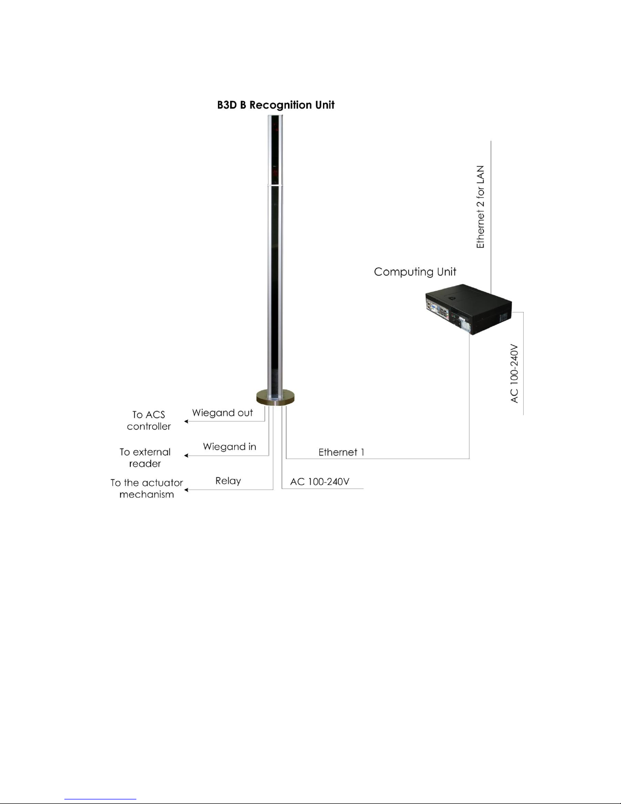
3.2. B3D B ........................................................................................................... 6
3.3. B3D BM ........................................................................................................ 7
4. Integration with ACS ....................................................................................... 8
5. HW Specifications ......................................................................................... 10
5.1. B3D BR Recognition Unit ............................................................................ 10
5.2. B3D B Recognition Unit .............................................................................. 14
5.3. B3D BM Recognition Unit ........................................................................... 19
5.4. Recognition Unit mounting set ................................................................... 24
5.5. Computing Unit .......................................................................................... 25
5.6. B3D Controller ............................................................................................ 27
5.7. VGA Extenders ........................................................................................... 29
6. Mechanical Installation ................................................................................. 31
6.1. B3D BR ....................................................................................................... 31
6.2. B3D B ......................................................................................................... 34
6.3. B3D BM ...................................................................................................... 40
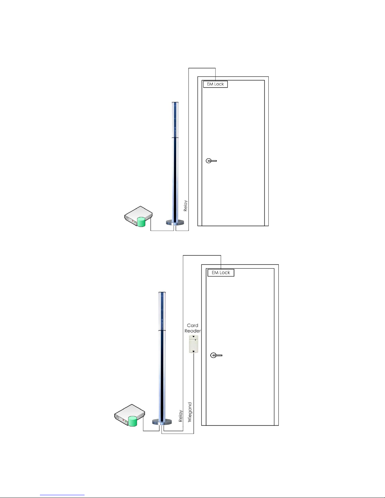
6.4. B3D Connection with Access Control Systems ............................................ 47

3
1. General Information
The Broadway 3D (B3D) security system is designed for building highly reliable biometric stand-alone
access control systems (ACS). B3D system reads biometric information about face shape, compares it
with those biometric templates registered in the database, and makes the decision to issue control
signals to actuators controlling access to premises (turnstiles, locks, gates, etc.), while simultaneously
displaying information on the status of work on a monitor and LED indicators.
B3D system can also complement existing access control systems that are based on other identification
technologies, in order to improve their reliability and functionality. In those cases, B3D system interacts
with elements of the access control system - access control card readers and/or controllers having a
Wiegand interface.
B3D system can operate in either identification or verification mode. The type of biometric template
remains unchanged. Therefore, during operation of the system, at any time the system can be switched
from one mode to the other. If several B3D systems work as an integrated solution, then some of them
may operate in the mode of verification, and some in the mode of identification.

4
2. Delivery Package
B3D systems come in the packages described in Table 1.
Component
B3D version B
B3D version BM
B3D version BR
3D Camera
+
+
+
B3D Pole
+
+
o
Recognition Unit mounting set
+
+
o
Docking station
+
+
+
Computing Unit
+
+
+
VGA Extender
o
+
o
Monitor
o
+
o
Packaging
+
+
+
ASP software package
+
+
+
User Manual
+
+
+
Table 1. B3D packages
B3D Poles vary between B3D versions. Packaging may vary between B3D Versions. The rest components
are the same for all B3D versions, if included.

5
3. Electrical Connection Diagram
3.1. B3D BR
Figure 1 illustrates basic electrical connection diagram of B3D BR system.
FIG 1. B3D BR basic electrical connection diagram

6
3.2. B3D B
FIG 2. B3D B optional electrical connection diagram

7
3.3. B3D BM
FIG 3. B3D BM optional electrical connection diagram

8
4. Integration with ACS
Figures 4 to 7 show typical scenarios of integration of B3D B/BM/BR with Access Control Systems.
FIG 4. Integration with an actuator
FIG 5. Integration with an actuator and a card reader

9
FIG 6. Integration with a door controller
FIG 7. Integration with a door controller and a card reader

10
5. HW Specifications
5.1. B3D BR Recognition Unit
5.1.1. Overview
B3D BR Recognition Unit is a part of B3D system that end users directly interact with. The Recognition
Unit is always installed at point of access (e.g. doors and turnstiles) with exception of cases when it is
used not for access control purposes but only as an enrollment station. The Recognition Unit captures
3D facial biometric of users, sends that data over Ethernet to the Computing Unit and provides
interaction with third parties Access Control Systems components via embedded B3D controller. The
Recognition Unit also provides users with visual feedback information about the B3D system and
recognition process conditions with the LED indication.
B3D BR Recognition Unit is an OEM unit. It may be mechanically integrated in and mounted on a
turnstile, wall, door, reception desk, tripod, and etc.
FIG 8. B3D BR Recognition Unit
5.1.2. B3D BR Recognition Unit package
B3D BR Recognition Unit package includes:
3D Camera
Docking station
Ethernet patch-cord
Power supply
Power cord
B3D BR Recognition Unit comes without any mounting set. Its mounting method depends on particular
integration and/or installation conditions. Mounting set for specific conditions may be designed and
delivered by the manufacturer upon order.

11
5.1.3. B3D BR Recognition Unit general drawing
FIG 9. B3D BR Recognition Unit general drawing
FIG 10. B3D BR Recognition Unit general drawing bottom view

12
5.1.4. B3D BR Recognition Unit field-of-view
FIG11.B3DBRRecognitionUnit’shorizontalfield-of-view
FIG 12. B3D BR Recognition Unit vertical field-of-view

13
5.1.5. B3D BR Recognition Unit electrical connections
FIG 13. B3D BR Docking station connections
B3D BR Recognition Unit connectors:
Power socket Switchcraft L722RA
Ethernet socket RJ-45 jack
Connector #1 #2 Weidmuller 1045390000
Counterpart connectors:
Power plug Switchcraft S761K
Ethernet plug TP-8P8C plug
Connector #1 #2 Weidmuller 1748520000
Details and specifications of Connector #1 and #2 are described in Chapter 5.6.
5.1.6.B3DBRRecognitionUnit’scharacteristics
Parameter
Value
Interface
Ethernet, Wiegand, Relay
Ethernet line distance, up to
90 meters
Working distance
0,8 – 1,6 m
Linear field of view, HxW @ closest range
646x490 mm
Linear field of view, HxW @ furthest range
1292x980 mm
Angular field of view, HxW
44х340
Light source
Flash bulb (no laser)
Video frame rate, up to
15 fps
Exposure time
0,2 ms
Dimensions, HxDxW
470х129х94mm
Weight
3,5 kg
Power consumption
100-240 VAC @ 60 W
Operating temperature
15 – 30 0С
Operating humidity
15% - 80% non-condensing
Table 2. B3DBRRecognitionUnit’scharacteristics

14
5.2. B3D B Recognition Unit
5.2.1. Overview
B3D B Recognition Unit is a part of B3D system that end users directly interact with. The Recognition
Unit is always installed at point of access (e.g. turnstiles) with exception of cases when it is used not for
access control purposes but only as an enrollment station. The Recognition Unit captures 3D facial
biometric of users, sends that data over Ethernet to the Computing Unit and provides interaction with
third parties Access Control Systems components via embedded B3D controller. The Recognition Unit
also provides users with visual feedback information about the B3D system and recognition process
conditions with the LED indication.
B3D B Recognition Unit is meant to be mounted on the floor.
FIG 14. B3D B Recognition Unit
5.2.2. B3D B Recognition Unit package
B3D B Recognition Unit package includes:
3D Camera
B3D B Pole
Ethernet patch-cord
Power supply

15
The following description applies B3D B Recognition Unit as an assembly.
5.2.3. B3D B Recognition Unit general drawing
FIG 15. B3D B Recognition Unit general drawing

16
5.2.4. B3D B Recognition Unit field-of-view
FIG16.B3DBRRecognitionUnit’shorizontalfield-of-view
FIG 17. B3D B Recognition Unit vertical field-of-view

17
5.2.5. B3D B Recognition Unit electrical connections
B3D B has one 3D Camera and three power supply connectors. Connectors are located inside the lower
part of the B3D B Pole. The connectors are accessible through a window located on the lower back part
of the B3D Pole. Each power supply connector is dedicated to one electrical line - null, phase and
ground.
FIG 18. B3D B Recognition Unit connections
B3D B Recognition Unit connectors:
Power terminal 12V Phoenix Contact FFKDS/H1
Power terminal 100-220V WAGO-264
Ethernet socket RJ-45 jack
Connector #1 #2 Weidmuller 1045390000
Counterpart connectors:
Power cable 12V AWG 22 - 16
Power cable 100-220V AWG 28 - 12
Ethernet plug TP-8P8C plug
Connector #1 #2 Weidmuller 1748520000
Details and specifications of Connector #1 and #2 are described in Chapter 5.6.

18
5.2.6. B3D B Recognition Unit characteristics
Parameter
Value
Interface
Ethernet, Wiegand, Relay
Ethernet line distance, up to
90 meters
Working distance
0,8 – 1,6 m
Linear field of view, HxW @ closest range
646x490 mm
Linear field of view, HxW @ furthest range
1292x980 mm
Angular field of view, HxW
44х340
Light source
Flash bulb (no laser)
Video frame rate, up to
15 fps
Exposure time
0,2 ms
Dimensions, HxDxW
1657х230х230mm
Weight
17 kg
Power consumption
100-240 VAC @ 60 W
Operating temperature
15 – 30 0С
Operating humidity
15% - 80% non-condensing
Table 3. B3DBRecognitionUnit’scharacteristics

19
5.3. B3D BM Recognition Unit
5.3.1. Overview
B3D BM Recognition Unit is a part of B3D system that end users directly interact with. The Recognition
Unit is always installed at point of access (e.g. turnstiles) with exception of cases when it is used not for
access control purposes but only as an enrollment station. The Recognition Unit captures 3D facial
biometric of users, sends that data over Ethernet to the Computing Unit and provides interaction with
third parties Access Control Systems components via embedded B3D controller. The Recognition Unit
also provides users with visual feedback information about the B3D system and recognition process
conditions with the LED indication and the monitor.
B3D BM Recognition Unit is meant to be mounted on the floor.
FIG 19. B3D BM Recognition Unit

20
5.3.2. B3D BM Recognition Unit package
Broadway 3D BM Recognition Unit package includes:
3D Camera
B3D BM Pole
Monitor
Ethernet patch-cord
Power supply
VGA Extender
The following description applies B3D BM Recognition Unit as an assembly.
5.3.3. B3D BM Recognition Unit package general drawing
FIG 20. B3D BM Recognition Unit general drawing
This manual suits for next models
2
Table of contents