Arthur Grillo DS200 User manual

Installation and operation manual
DS200
DIFFERENTIAL PRESSURE SENSOR
Low pressure sensor with display, analogue output and
selectable measurement range.
Doc.-no.: DS200_01_EN Issue: 05/2017

2Doc.-no.: DS200_01_EN Issue: 05/2017
Manufacturer:
Phone:
Fax:
E-mail:
Website:
Issue:
Doc.-no.:
Arthur Grillo GmbH
Am Sandbach 7
40878 Ratingen
0 21 02 - 47 10 22
0 21 02 - 47 58 82
www.grillo-messgeraete.de
www.sensor-store.de
05/2017
DS200_001_EN
This documentation including all parts is protected by copyright.Any utilisation or modi-
cation other than permissible under the strict limitations of copyright law is prohibited
and liable to prosecution without the approval of the Arthur Grillo GmbH. This applies
in particular to duplications, translations, microlming and storage and processing in elec-
tronic systems.

3
Doc.-no.: DS200_01_EN Issue: 05/2017
TABLE OF CONTENT
Table of content
1 General safety instructions
1.1 Signal words for safety instructions
1.2 Used pictograms and symbols
1.3 General notes
2 Product description
2.1 Type plate
2.2 Intended use
2.3 Functional description
3 Installation
3.1 Dimensions
3.2 Wall mounting
4 Start up
4.1 Overview DPC200-R
4.2 Schematic view inside
4.3 Pressure connections
4.4 Electrical connection
4.5 Zero adjustment
5 Operation
5.1 Start menu
5.2 Menu structure
5.3 Measuring mode
5.4 Control mode
5.5 Adjustable parameters
5.6 Threshold calculation
5.7 Function relay alarm output
6 Maintenance
7 Warranty
8 Troubleshooting
9 Disposal
10 Specications
10.1 CE-labelling
04
04
04
04
05
05
05
05
06
06
06
07
07
07
07
08
08
08
08
09
10
11
12
13
13
14
14
14
14
15
16

4Doc.-no.: DS200_01_EN Issue: 05/2017
GENERAL SAFETY INSTRUCTIONS
1. General safety instructions
1.1 Signal words for safety instructions
The safety instructions in this operation manual are designed to prevent hazards.They can
be found in the operation manual before an operation / task / activity is described, which
can entail a possible hazard.
Identication of a hazard with a low risk, which can lead to material
damage or minor or moderate bodily injuries.
CAUTION
1.2 Used pictograms and symbols
In this manual the following symbols are used:
General hazard symbol (dan-
ger, warning, caution)
Signal word for important information regarding the product, which
needs to be specically pointed out.
NOTICE
Hazard word Type of hazard
Hazard source
Hazard prevention
1.3 General notes
This manual contains information for installation and operation of
the DS200 and is exclusively for the operator and expert staff. The
guidelines in this manual will help to avoid danger and downtime.
NOTICE
General information

5
Doc.-no.: DS200_01_EN Issue: 05/2017
2. Product description
The airow / pressure controller DS200 measures low pressure of inert gases, particu-
larly of air.
2.1 Type plate
1. Product name
2. Measuring range
3. Supply voltage
4. Signal output
5. Serial no.
6. Manufacturer
2.2 Intended use
The application range of the DS200 is for example:Fan control in air conditioning systems,
pressure or lter control in rooms. As analogue output the operator can use a signal from
0...10 V DC.The output signal proceeds proportional to the measured pressure.
2.3 Functional description
A soft silicone diaphragm is used as sensor. Under the inuence of the differential pressure
the membrane displaces against a measuring spring until spring force compensates the
pressure charging on the diaphragm. A contactless differential transformer and suitable
electronics convert this displacement into a continuously variable output voltage signal.
The DS200 has four calibrated measuring ranges, which can be selected via the software
menu. A two-line alphanumeric LCD display shows the measured pressure in the physical
unit.
In combination with a differential pressure transducer (orice plate, venturi or pitot tube),
the DS200 also directly display the ow in a pipeline. For this purpose, the differential pres-
sure of the transducer is square root and multiplied by an adjustable factor of the transducer.
A damping of output signal because of uctuating measured values, can be adjusted in four
stages via DIP switches.
The differential pressure sensor DS200 delivers an analogue output signal of 0/2...10 V or
0/4...20 mA.The supply voltage is 17...30 Vdc or 24 Vac.
PRODUCT DESCRIPTION
Tabelle1
Seite 1
DS200-10
0 … 1000 Pa
IP54
Differential Pressure Sensor
measurement range:
serial-no.: 17.372 part-no.: 2561
supply voltage: U
S
(1+ 2-) = 17 ... 30 Vdc / 24 Vac
signal output: U
out
(3+ 4-) =
O
0/2 ... 10 V
O
0/4 ...20 mA
O
0...1000 Pa
O
0...500 Pa
O
0...300 Pa
O
0...200 Pa
Arthur Grillo GmbH • Ratingen Made in Germany
1.
2.
3.
4.
5.
6.

6Doc.-no.: DS200_01_EN Issue: 05/2017
INSTALLATION
3. Installation
The differential pressure sensor DS200 has to be mounted vertically,to assure the accuracy.
The connection of the pressure lines is done by plastic tubes with an internal
Material damage
Read the manual carefully before installation and operation
Only experienced stuff may connect the device and bring it into
operation.
CAUTION
3.1 Dimensions
All dimensions in mm.
• The device is position depended.
• The DS200 must be mounted vertically
• The DS200 can be attached to a wall.
NOTICE
3.2 Wall mounting
1. Hold the DS200 against the wall. Mark the mounting holes.
2. Drill mounting holes for properly sized screws.
3. Put the screws through the housing mounting holes.
4. Tighten screws.
ø6
ø5
M16 X 1.5
4.5
-+
104
54
95
70

7
Doc.-no.: DS200_01_EN Issue: 05/2017
START UP
4. Start up
4.1 Overview DS200
1. Front cover
2. Cable gland M16 x 1.5
3. Pressure connection 1
4. Pressure connection 2
5. Cable gland M16 x 1.5
1.
2.
3.
4. 5.
4.2 Schematic view inside
4E140-L3
19.07.2016Koep
DS200_2Bedienung
P1
J1
DIP
4
T2
T1
6
5
3
2
1
1:1
Maßstab
ArthurGrillo GmbH·Ratingen
Datum
BenennungZeichnungs-Nr.
NameSign.
button 1 button 2
DIP-switch
jumper
Button: The button 1 and 2 are for the menu operation.
DIP-switch: The uctuating measurement values can be lowered via a DIP-switch.
Jumper: The analogue output can be switched from voltage to power via a jumper.
(For more information please check chapter 5.3)
4.3 Pressure connections
Connect all pressure connections properly with plastic tubing (inner diameter 5 or 6mm).

8Doc.-no.: DS200_01_EN Issue: 05/2017
OPERATION
4.4 Electrical connection
Adjustment:
• Remove the tubing from the pressure
connections.
• Hold the bar magnet (N/S) as shown here
to the zero point adjustment for a short
period of time to activate an internal reed
switch.
The new zero point will be displayed and
stored.
5. Operation
5.1 Start menu
For operating the menu, unscrew the front cover to reach buttons T1 and T2.
N S
1. Unscrew screws of the front cover.
2. Open front cover.
3. Use the M16 x 1.5 screw for connecting to terminals.
4.5 Zero adjustment
The zero point can be adjusted independently from the menu. For readjusting please use
the small bar magnet and be sure that the device is not in menu mode.
ΔP
ΔP
+17...30 Vdc oder 24 Vac (±15%) Versorgung

9
Doc.-no.: DS200_01_EN Issue: 05/2017
OPERATION
5.2 Menu structure

10 Doc.-no.: DS200_01_EN Issue: 05/2017
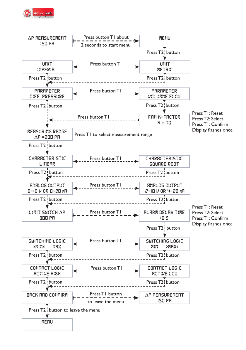
OPERATION
Parameters Selection or parameter range Default
Unit metric or imperial metric
Parameter Differential pressure ΔP [Pa or InH2O]
Volume flow V [m3/h or cfm]
differential
pressure
ΔP [Pa]
K-factor: K = 70
Measurment
range: MB1
Characteristic: linear or square rooted linear
Analogue
output: 0...10 V / 0...20 mA or 2...10 V / 4...20 mA 0...10 V /
0...20 mA
Limit value:
• Differential pressure from 0% up to 100% of
measuring range.
• Volume flow from 5% up to 100% of measuring
range, k-factor is considered.
OFF
alarm delay
time
Switching delay time adjustment range:
1...60 seconds or 2....15 minutes 10 s
Switching
logic Switching logic MIN or MAX MAX
Contact logic Contact logic active high or active low active high
MBI MB2 MB3 MB4
DS200-2 - 200 Pa 150 Pa 100 Pa 50 Pa
DS200-10 - 1.000 Pa 500 Pa 300 Pa 200 Pa
DS200-60 - 6.000 Pa 4.000 Pa 3.000 Pa 2.000 Pa
Volume flow calculation according to: V = k · √Δp
with:
• V = Volume flow in m3/h or cfm
• k = flow factor, adjustment range: 1...10,000
• Δp = differential pressure in Pa or InH20
Calculation up to: 999,999 m3/h (587.999 cfm)
Maximum volume flow (Vmax):
Measuring range: 200 Pa, k=10.000
Vmax = 141.421 m3/h; (83.155 cfm)
Measuring range: 1000 Pa, k=10.000
Vmax = 316.228 m3/h; (185.942 cfm)
Measuring range: 6000 Pa, k=10.000
Vmax = 774.597 m3/h; (37.188 cfm)
5.2 Adjustable parameters - Software

11
Doc.-no.: DS200_01_EN Issue: 05/2017
OPERATION
Choice of analogue input:
The analogue output can be switched via a jumper from voltage 0/2...10V (horizontal
down) to 0/4...20 mA (horizontal up). The potentiometer P1 allows ne tuning of the
current output or a burden adjustment.
5.3 Adjustable parameters - hardware
Damping levels: In case of uctuating measured values different damping levels can be
adjusted via the DIP-switches no.1 and no. 2.
DIP 1 DIP 2
No damping off off
Time constant 0,5 s on off
Time constant 1s off on
Time constant 1,5 s on on
4E140-L3
19.07.2016Koep
DS200_2Bedienung
P1
J1
DIP
4
T2
T1
6
5
3
2
1
1:1
Maßstab
ArthurGrillo GmbH·Ratingen
Datum
BenennungZeichnungs-Nr.
NameSign.
DIP-switch jumper

12 Doc.-no.: DS200_01_EN Issue: 05/2017
OPERATION
5.4 Error limits (related to the actual range)
DS200-10
0...1000 Pa ± 0.5 % ± 0.5 % ± 0.25 % 0,1 % 0.2 %
0...500 Pa ± 0.7 % ± 0.7 % ± 0.5 % 0.2 % 0.2 %
0...300 Pa ± 0.9 % ± 0.9 % ± 0.9 % 0.3 % 0.2 %
0...200 Pa ± 1 % ± 1 % ± 1.25 % 0.3 % 0.2 %
DS200-60
0...6000 Pa ± 0.5 % ± 0.5 % ± 0.25 % 0.1 % 0.2 %
0...4000 Pa ± 0.7 % ± 0.7 % ± 0.4 % 0.15 % 0.2 %
0...3000 Pa ± 0.9 % ± 0.9 % ± 0.6 % 0.2 % 0.2 %
0...2000 Pa ± 1 % ± 1 % ± 0.75 % 0.25 % 0.2 %
DS200-2
0...200 Pa ± 0.5 % ± 0.5 % ± 0.25 % 0.1 % 1 %
0...150 Pa ± 0.75 % ± 0.6 % ± 0.4 % 0.2 % 0.7 %
0...100 Pa ± 1 % ± 0.7 % ± 0.5 % 0.2 % 0.5 %
0...50 Pa ± 2 % ± 1 % ± 1 % 0.3 % 0.5 %
5.5 Function alarm output
The DS200 has an open collector alarm output.
When an alarm occurs, an exclamation mark (!) indicates the alarm state (2nd line / 16th
character).
The open collector output has two different states:
• Highly resistive to disable external circuit
• Low-resistance, to connect an external circuit with maximum load of 30Vdc / 30 mA
For limit value monitoring,a limit value can be entered under the menu item “limit switch”.
The previously set parameters are taken into account (unit, measured variable,k-factor and
the measuring range). In the basic state, the limit values are not active, and the menu item
“limit switch” shows “OFF” in the second line.
Zero
deviation
deviation
Final value
Linearity
Resolution
Hysteresis

13
Doc.-no.: DS200_01_EN Issue: 05/2017
OPERATION
The output is subject to the following logic with regard to hysteresis and the set
switching delay time:
MAX
switching
logic:
Alarm ON, low resistance
• if ΔP > limit value for set switching delay time
Alarm OFF, high resistance
• if ΔP < 0,95 x limit value for set switching delay time
MIN
switching
logic:
Alarm ON, low resistance
• if ΔP < limit value for set switching delay time
Alarm OFF, high resistance
• if ΔP > 1,05 x limit value for set switching delay time
Three menu items, which inuence the switching behavior of the open collector
output, follow the „limit switch“ menu item:
1. “alarm delay time” with this menu item the switching delay time can be set.The
setting range is 1...60 s or 2...15 min. In the basic state, this value is set to 10 seconds
2.“switching logic” here you have the possibility to set the limit values to MAX or
MIN.At MAX, an alarm is triggered,when the measured value exceeds the limit value;
at MIN, the alarm is triggered when the limit value is exceeded.
3.“Contact logic” the rest state or the switching state of the open collector output
can be set differently.“Active high” means that when an alarm occurs, the open col-
lector output becomes low-impedance.“Active low” means that the alarm switches
the open collector output high-impedance
The following switching pattern can be summarized:
switching
logic
contact
logic pressure alarm output display
MAX active
high
ΔP > limit value alarm ON, low resistance !
ΔP < limit value alarm OFF, high resistance
MAX active
low
ΔP > limit value alarm ON, high resistance !
ΔP < limit value alarm OFF, low resistance
MIN active
high
ΔP > limit value alarm OFF, high resistance
ΔP < limit value alarm ON, low resistance !
MIN active
low
ΔP > limit value alarm OFF, low resistance
ΔP < limit value alarm ON, high resistance !

14 Doc.-no.: DS200_01_EN Issue: 05/2017
6. Maintenance
The DS200 contains no wearing or consumable parts. Servicing is not required.
On request, Arthur Grillo GmbH offers an annual calibration with factory certicate.
For information, please contact:
7. Warranty
Warranty and liability claims for personal and property damage are excluded if they are
caused by one or more of the following reasons:
• Improper use of the device.
• Improper installation, commissioning, operation and maintenance of the device.
• Unauthorized modications to the device beyond the intended use.
• Disasters due to external inuences and force majeure.
8. Troubleshooting
9. Disposal
Dispose of parts so as not to endanger the human health or environment. Follow the laws
in the country of use for disposing of electronic components and devices during disposal.
Description Activity
Display does not show
anything Check electrical connection
Measurement stays zero Function test with a slight pressure increase in measu-
ring mode for differential pressure
Measuring error Perform zeroing as described in chapter 4.5.
Error remains Contact manufacturer
Display shows: ! The device is in the alarm state, see section 5.5
WARRANTY & SUPPORT
Arthur Grillo GmbH Phone: +49 21 02 - 47 10 22
Am Sandbach 7 Fax: +49 21 02 - 47 58 82

15
Doc.-no.: DS200_01_EN Issue: 05/2017
SPECIFICATIONS
10. Specications
Overpressure
protection:
Static pressure:
Zero point calibration:
Response time:
Operating mode:
Measuring medium:
Measuring principle:
Measuring unit:
Measuring range:
Range selection:
Characteristic:
Damping:
Ambient temperature:
Storage temperature:
Setpoint settings:
signal / alarm output:
Alarm delay time:
Switching logic:
Contact Logic:
Housing:
Dimensions:
Weight:
Protection class:
Display:
Electrical connections:
Pressure connections:
Operational position:
Power supply:
Power consumption:
Output:
0,2 bar
max. 0,2 bar
adjustable by REEDcontact, no cyclic zero-point calibration
required
direct
measuring mode
air or non-aggressive gases
electromechanical diaphragm measuring system
Pa / InH20 or m3/h or cfm
DS200-P2: 0…200 Pa, 0…150 Pa, 0...100 Pa, 0…50
DS200-P10: 0…1000 Pa, 0…500 Pa, 0…300 Pa, 0…200 Pa
DS200-P60: 0…6000 Pa, 0…4000 Pa, 0…3000 Pa, 0…2000 Pa
by software menu
linear or radiated selectable by software menu
adjustable in 3 steps
-10...+50 °C
-25...+60 °C
1 limit can be set via software menu
open collector, max 30 V / 30 mA
freely adjustable in the range of
0 ... 60 seconds - 2 ... 15 minutes
MIN or MAX
active high or active low
UL 94 HB; Ultramid with hinged lid of ABS
95 x 70 x 54 mm (w x h x d)
approx. 250 g
IP 54 according EN 60529
two-line alphanumeric LCD display, 2 x 16 characters
cable entry M16x1.5, screw terminals, electronics protected
against incorrect polarity
hose connections 5 mm ø and 6 mm ø
vertical, position dependence when rotated through 90°
approx. 25 Pa
17...30 Vdc or 24 Vac ± 15 %
approx. 6 mA @ 17 Vdc and 0...10 V output
approx. 19 mA @ 30 Vdc and 0...10 V output
0/2...10 V(Imax = 10 mA @ 20 Vdc, Imax = 17 mA @ 30 Vdc) /
0/4...20 mA, max load 200 Ω

16 Doc.-no.: DS200_01_EN Issue: 05/2017
CE-LABELLING
10.1 CE-labelling
As an electric device the DS200 falls within the scope of the directive 2004/108/EG
(EMV-directive). In the scope of the EMV-directive the following norms were applied:
DIN EN 61000-6-2:2006-03
correction 1:2011-06
Electromagnetic compatibility (EMC) - Part 6-2: Generic
standards - Immunity for industrial environments
DIN EN 61000-6-3:2011-09
Electromagnetic compatibility (EMC) - Part 6-3: Generic
standards - Emission standard for residential, commer-
cial and light industrial environments
You can order the Declaration of Conformity at:
Arthur Grillo GmbH
Am Sandbach 7
40878 Ratingen
Phone: 0 21 02 - 47 10 22
Fax: 0 21 02 - 47 58 82
E-mail: [email protected]
Table of contents
Other Arthur Grillo Accessories manuals