Arthur Grillo PFT Series User manual

Doc.-no.: PFT_01_EN Issue: 05/2017
Operating and installation instructions
Combined measuring transducer for the HVAC application
Transmitters of the PFT series
for rel. humidity and temperature

2Doc.-no.: PFT_01_EN Issue: 05/2017
Manufacturer:
Phone:
Fax:
E-mail:
Website:
Issue:
Doc.-no.:
Arthur Grillo GmbH
Am Sandbach 7
40878 Ratingen
0 21 02 - 47 10 22
0 21 02 - 47 58 82
www.grillo-messgeraete.de
www.sensor-store.de
05/2017
PFT_001_EN
This documentation including all parts is protected by copyright.Any utilisation or modi-
cation other than permissible under the strict limitations of copyright law is prohibited
and liable to prosecution without the approval of the Arthur Grillo GmbH.This applies
in particular to duplications, translations, microlming and storage and processing in elec-
tronic systems.

3
Doc.-no.: PFT_01_EN Issue: 05/2017
TABLE OF CONTENT
Table of content
1 General safety instructions
1.1 Signal words for safety instructions
1.2 Used pictograms and symbols
1.3 General notes
2 Product description
2.1 Intended use
2.2 Functional description
2.3 Measured values at output 2 (only PFT25 /28)
3 Installation
3.1 Dimensions
4 Electrical connection
5 Operation
5.1 Starting up
5.1.1 PFT28 - Selection of measured values
5.1.2 PFT22 - Selection of measured values
5.1.3 PFT25 - Selection of measured values
5.2 Selection options via T-button (PFT 28)
5.3 Protection at high humidity (PFT 28)
6 Maintenance
7 Warranty
8 Troubleshooting
9 Disposal
10 Specications
10.1 CE-labelling
04
04
04
04
05
05
05
05
06
06
08
09
09
09
11
11
11
12
12
13
13
13
13
16

4Doc.-no.: PFT_01_EN Issue: 05/2017
GENERAL SAFETY INSTRUCTIONS
1. General safety instructions
1.1 Signal words for safety instructions
The safety instructions in this operation manual are designed to prevent hazards.They can
be found in the operation manual before an operation / task / activity is described, which
can entail a possible hazard.
Identication of a hazard with a low risk, which can lead to material
damage or minor or moderate bodily injuries.
CAUTION
1.2 Used pictograms and symbols
In this manual the following symbols are used:
General hazard symbol (dan-
ger, warning, caution)
Signal word for important information regarding the product, which
needs to be specically pointed out.
NOTICE
Hazard word Type of hazard
Hazard source
Hazard prevention
1.3 General notes
This manual contains information for installation and operation of
the PFT and is exclusively for the operator and expert staff. The
guidelines in this manual will help to avoid danger and downtime.
NOTICE
General information

5
Doc.-no.: PFT_01_EN Issue: 05/2017
2. Product description
Our PFT are combined measuring transducers for the measurement of rel. humidity and
temperature.
Special features of the individual devices:
PRODUCT DESCRIPTION
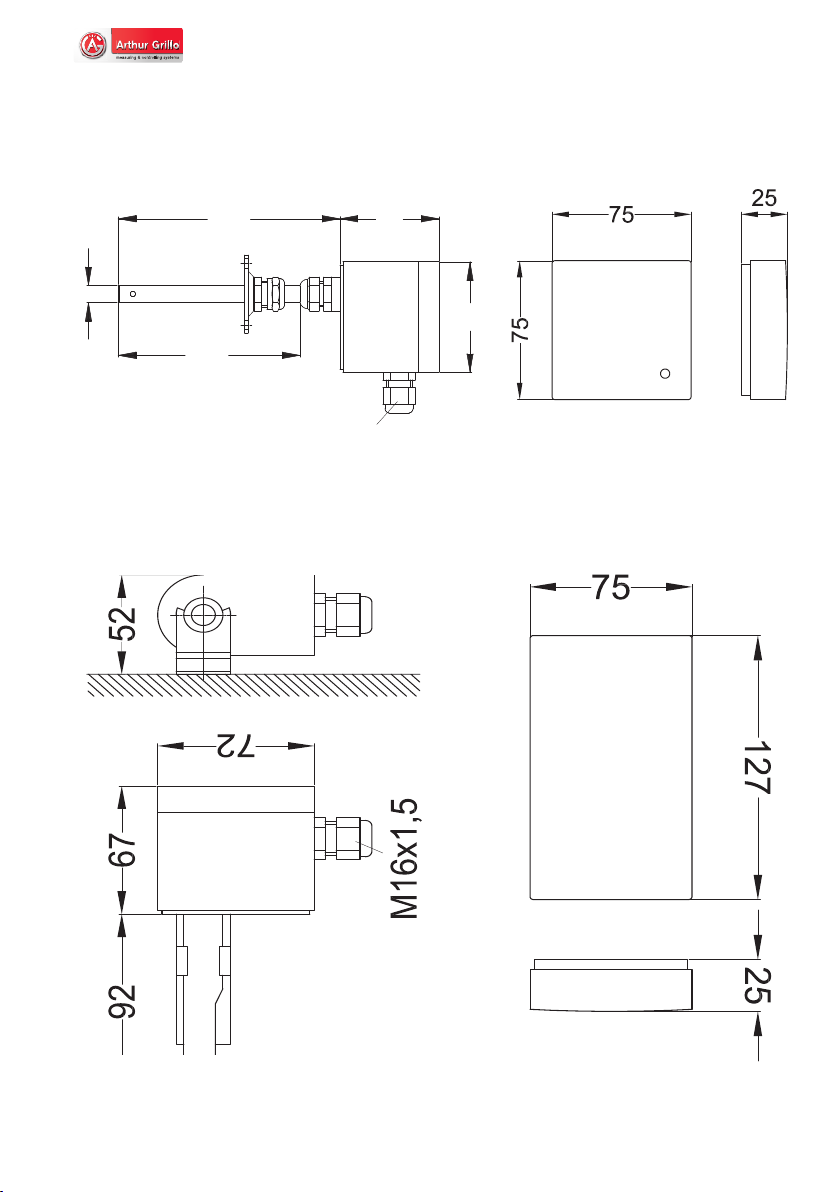
For the application areas of sewer / pipe systems, indoor area or in the outdoor and wet
area, we provide various special designed housings.
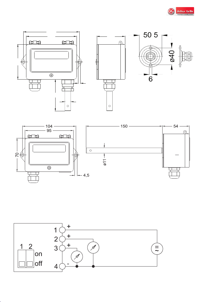
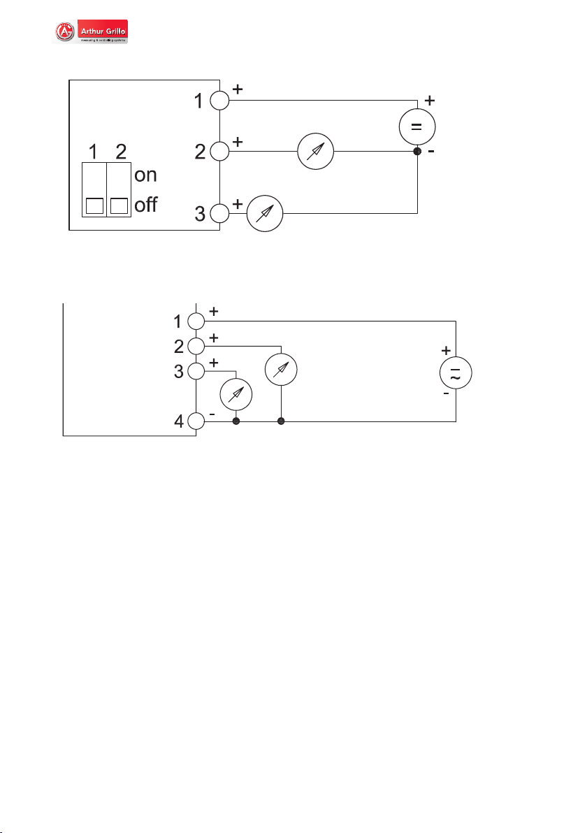
Our PFT22 and PFT25 are both designed as two-wire technology with two output signals
of 4...20 mA or as three-wire technology with two outputs of 0...10V. The supply voltage
of the two-wire technology is 15...30 Vdc, in three-wire technology it is 24 Vdc or 24Vac.
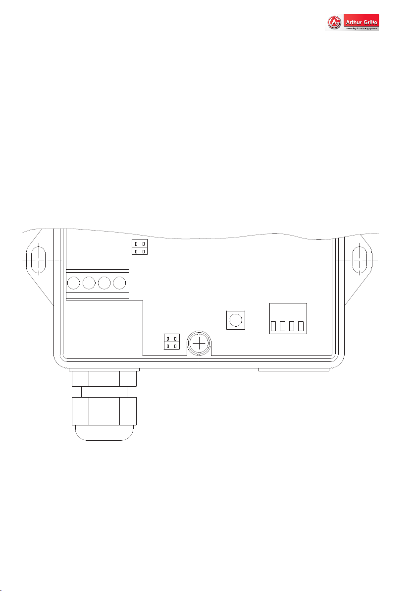
As PFT28 it is supplied with 15...30Vdc or 24 Vac, with a jumper the output signals can be
switched from 0/2...10 V to 0/4...20 mA.
2.1 Intended use
The combined transducers of the PFT series are used for measuring / signal transmission
of relative humidity and temperature in the application area of heating and air-conditioning.
2.2 Functional description
Our PFT devices are equipped with a single-chip sensor for an optimal measurement of
relative humidity and temperature. Depending on the application the sensor chip is located
in a stainless steel probe tube or is housed directly in an ABS plastic housing.The signi-
cant parts of sensors are: Two sensor units (capacitive measuring principle for relative
humidity and semiconductor principle for temperature), a signal amplication, a 14-bit
A / D converter and a digital two-wire interface. Furthermore, there is a OTP memory
located on this chip, which stores the calibration data of both capturing principles. The
signal transmission from sensor to evaluation electronics takes place digitally.The sensor
- Two analog outputs:
1.Temperature -30...+50 °C
2. relative humidity, dew point temperature, enthalpy;
Special version: Absolute humidity
PFT25
- Two analog outputs:
1.Temperature with four switchables measuring ranges
2. relative humidity.
PFT22
- Display
- Selectable analog output: 0/2...10 V or 0/4...20 mA
- Two analog outputs:
1.Temperature -30...+50 °C
2. relative humidity, dew point temperature, enthalpy;
Special version: Absolute humidity
PFT28

6Doc.-no.: PFT_01_EN Issue: 05/2017
INSTALLATION
itself can be exchanged without any problems, since readjustment of the electronics are
not necessary after the replacement.
2.3 Measures values at output 2 for PFT25 / PFT28
Relative humidity (% rh)
The relative humidity is the percentage, which is present between the available moisture
and the maximum possible humidity at this temperature.
Dew point temperature (°C)
The dew point temperature is the temperature at which the cooling of moist air leads to
condensation.
Wet bulb temperature (°C)
The wet bulb temperature indicates the temperature at which a thermometer can be
cooled, which is provided with a damp coating and anti-corrosion protection.
Enthalpy (kJ / kg)
The enthalpy (heat content) is the heat energy that the humid air has stored. It is propor-
tional to the temperature of the humid air, and also depends on the water vapor content.
Absolute humidity (g / m³) (optional)
The absolute humidity is a direct measure for the quantity of water vapor contained in a
given air volume.
3. Installation
The outdoor sensor version is equipped with a short double-walled sensor tube as a ra-
diation and rain protection. Included in the delivery are a mounting ange for installation
in a duct and a wall mount for an installation at a wall.
The room sensor for indoor measurements can be mounted on a wall or directly on a
ush-mounted switch box. The position „top“ (within the housing) must be observed
during assembly.
Material damage
Read the manual carefully before installation and oper-
ation. Only experienced staff may connect the device
and bring it into operation.
CAUTION

7
Doc.-no.: PFT_01_EN Issue: 05/2017
INSTALLATION
3.1 Dimensions
All gures in mm.
(L1)
115
M16x1,5
72
ø11
15067
PFT22K / PFT25K
PFT22A / PFT25A
PFT22R / PFT25R
mit 0...10 V output
PFT22R / PFT25R
mit 4...20 mA output

8Doc.-no.: PFT_01_EN Issue: 05/2017
ELECTRICAL CONNECTION
rel. Feuchte
0...10 V
Temperatur
0...10 V
15...30
Vdc
output 2
0...10 V
output 1
0...10 V
15...30 Vdc
or 24 Vac
4.5
70
95 54
104
ø11
65
Baumaße PFT28R as room sensor
PFT28K as duct sensor
MountingangeMF-M90
2 x voltage output PFT22 / PFT25 - 0...10 V output
4. Electrical connection
.

9
Doc.-no.: PFT_01_EN Issue: 05/2017
OPERATION
output 2: 4...20 mA
output 1:
4...20 mA
13...30 Vdc
rel. Feuchte 4...20 mA
Temperatur
4...20 mA
13...30
Vdc
Ausgang 1:
Temperatur
Ausgang 2:
gewählte Messgröße
Output 1:
temperature
Output 2:
selected variable
15...30 Vdc
oder 24 Vac
15...30 Vdc
or 24 Vac
2 x current output PFT22 / PFT25 - 4...20mA output
2 x voltage output PFT28
Connection terminals:
1+ 4- Supply voltage 15...30 Vdc or 24 Vac (±15%)
2+ 4- Output 1: 0/2...10V or 0/4...20 mA
3+ 4- Output 2: 0/2...10 V or 0/4...20 mA
5. Operation
5.1 Starting up
To start up the device you have to set the nal conguration. Please remove the cover and
congure your nal setting via DIP switch and jumper.
5.1.1 PFT28 - Selecting the measured values
Please select the measured values via the DIP switches no. 3 and 4.Your selection is vie-
wable at the second line of the display.

10 Doc.-no.: PFT_01_EN Issue: 05/2017
OPERATION
4
3
2
1T
0/4...20mA
0/2...10V
0/4...20mA
0/2...10V
jumper 1
jumper 2
DIP switch
on
off
4
3
2
1
Signal range of the analog outputs:
voltage output: current output:
DIP no. 1 off 0...10 V 0...20 mA
DIP no. 1 on 2...10 V 4...20 mA
Selecting the analog output:
Both analog outputs can be switched from voltage 0/2...10 V) to current (0/4...20 mA) via
the jumper (see below).
DIP no. 3
off
on
off
on
DIP no. 4
off
off
on
on
Measured values:
relative humidity
dew point temperature
wet bulb temperature
enthalpy
= 0...100% rF
= -30...+50 °C
= -30...+50 °C
= 0...200 kJ/kg
rh
td
tf
E
jumper 1
up
down
- output 2
- 0/4...20 mA
- 0/2...10 V
- output 1
- 0/4...20 mA
- 0/2...10 V
jumper 2
up
down

11
Doc.-no.: PFT_01_EN Issue: 05/2017
OPERATION
5.1.2 PFT22 - Selection of measured values
The selection of the temperature measuring range at output 1
Special measuring ranges are possible!
5.1.3 PFT25 - Selection of measured values
The selection of the temperature measuring range at output 2
The absolute humidity measurement is possible on customer request (0...50.0 g/m³)
5.3 Selection options via the T-button (PFT28)
With the T-button (see Fig. 1), the various measured values can be switched through.
Therstdisplay-linealwaysshowsthetemperaturet(°C).
The DIP-switches No. 3 and No. 4 are used to select the measured value for the analog
output 2 and your selection is shown on the LCD displays second line.Via theT-button it is
possible to switch the second line of the LCD separately from the analog output. Holding
down the T-button changes the measured value on the LCD every second.
You can switch between:
1.) relative humidity 2.) dew point temperature
3.) wet bulb temperature 4.) enthalpy
As long as the T-button is pressed, this sequence is repeated continuously. To conrm a
measured value, please release theT-button, when the desired measured variable is shown.
After selecting a measured variable the displayed measured value does not change even
the DIP-switches No. 3 and No. 4. are shifted. Your selection is retained as long as the
voltage supply is maintained.
DIP no. 1
off
on
off
on
DIP no. 2
off
off
on
on
range:
-40...+120°C
-30...+70°C
0...+100°C
0...+50°C
DIP-switch
DIP no. 1
off
on
off
on
DIP no. 2
off
off
on
on
measuring range:
relative humidity
dew point temperature
wet bulb temperature
enthalpy
= 0...100 % rh
= -30...+50 °C
= -30...+50 °C
= 0...200 kJ/kg
rh
td
tf
E
DIP-switch

12 Doc.-no.: PFT_01_EN Issue: 05/2017
OPERATION
5.4 Protection function at high humidity (PFT28)
The PFT28 has a special sensor protection function, which will be activated at a high hu-
midity range.
In case a relative humidity rises to 98% an additional heating element will be activated.The
heating element heats up the sensor, till the humidity drops below 93% of relative humi-
dity. At this point the heating element switchs off automatically. Due to higher current
consumption, we recommmend a voltage supply of minimum 22 Vdc.
6. Maintenance
The PFT series contains no wearing or consumable parts. Servicing is not required. On
request, Arthur Grillo GmbH offers an annual calibration with factory certicate.
For information, please contact:
Arthur Grillo GmbH Phone: 0 21 02 - 47 10 22
Am Sandbach 7 Fax: 0 21 02 - 47 58 82

13
Doc.-no.: PFT_01_EN Issue: 05/2017
OPERATION
Single-chip sensor for relative humidity and temperature with
digital signal transmission and calibration memory on the chip.
Sensor tip on the sensor element with a lter made of sintered
bronze for protection against direct moisture and dust (lter
class CA75)
12 bits
linear (digital linearization)
approx. 4 seconds (63% time, slightly moving air)
typical <1% rh per year
Standard sensor: Sensor with restricted tolerance:
±0.1% rh
±3.5% rh at 30...70% rh
±5.0% rh at 0...29% rh
±5.0% rh at 71...100% rh
9. Disposal
Dispose of parts so as not to endanger human health or the environment. Follow the laws
in the country of use for disposing of electronic components and devices during disposal.
10. Technical details
Sensor:
Optional
sensor protection:
(Order no.: 72194)
Relative humidity:
Resolution:
Characteristics:
Reaction time:
Long term stability:
Reproducibility:
Tolerance:
Description Maßnahme
Display does not show anything Check electrical connection
Measurement stays zero Check the sensor element
Measuring error Contact manufacturer
7. Warranty
Warranty and liability claims for personal and property damage are excluded if they are
caused by one or more of the following reasons:
• Improper use of the device.
• Improper installation, commissioning, operation and maintenance of the device.
• Unauthorized modications to the device beyond the intended use.
• Disasters due to external inuences and force majeure.
8. Troubleshooting
±0.1% rh
±2.0% rh at 10...90 % rh
±4.0% rh at 0...9% rh
±4.0% rh at 91...100% rh

14 Doc.-no.: PFT_01_EN Issue: 05/2017
WARRANTY & SUPPORT
14 bits
linear
approx. 20 seconds
atandard sensor: Sensor with embedded tolerance:
±0.1°C ±0.1°C
±0.5°C at 25°C ±0.3°C at 25°C
±2.0°C at -40°C ±1.5°C at -40°C
±3.0°C at +120°C ±2.0°C at +120°C
ultramid with hinged lid of ABS
mounted sensor tube for receiving the sensor
IP 54 according to EN 60529; UL 94 HB
95 x 70 x 54 [mm] (w x h x d)
-25...+ 60 °C
approx. 300 g
15...30 Vdc; 24 Vac (±15%)
approx. 14 mA @ 24 Vac at 0...10 V output
two-line alphanumeric LCD, 2x16 characters
0/2...10 V or 0/4...20 mA with DIP switch and jumper
temperature -30...+50°C (other measuring ranges possible)
four selectable measured variables (DIP switches):
relative humidity:
dew point temperature:
wet bulb temperature:
enthalpy:
absolute humidity:
test according to EN 61000-6-2, EN 61000-6-3, CE mark
Temperature:
Resolution:
Characteristics:
Response time:
Reproducibility:
Tolerance:
PFT28:
Housing:
Protection class:
Dimensions:
Storage temperature:
Weight:
Power supply:
Power consumption:
Display:
Outputs:
Output 1:
Output 2:
Special
measuring range:
EMC:
=
=
=
=
=
0...100 %
-30...+50 °C
-30...+50 °C
0...200 kJ/kg
0...50 g/kg
rh
td
tf
E
ah
Duct:
Assembly:
Temperature range:
sensor tube made of stainless steel, 11 mm Ø at the back
mounting ange for attachment to the duct
sensor: -40...+120 °C
electronics: -10...+50 °C
Room:
Assembly:
Temperature range:
sensor tube made of stainless steel, 11 mm Ø at the front
mounting on the wall
sensor: -40...+120 °C
electronics: -10...+50 °C
Cable:
Assembly:
sensor tube made of stainless steel, 11mm Ø with 2m cable xed
mounting the housing on the wall, mounting ange for the sensor
tube

15
Doc.-no.: PFT_01_EN Issue: 05/2017
SPECIFICATIONS
linear
four selectable measuring ranges (DIP switches):
-40...+120 °C; -30...+70 °C; 0...100 °C; 0 to 50 °C
in the range from -40...+120 °C to customer specication
relative humidity 0...100% rh
2 x 0...10 V in three-wire circuit 4 connection terminals
2 x 4... 20 mA in two-wire circuit three connection terminals
15...30 Vdc or 24 Vac at three-wire circuit
13...30 Vdc at two-wire circuit
linear
temperature -30...+50 °C
four selectable measured variables (DIP switches):
relative humidity:
dew point temperature:
wet bulb temperature:
enthalpy:
absolute humidity:
2 x 0...10 V in three-wire circuit 4 connection terminals
2 x 4... 20 mA in two-wire circuit three connection terminals
15...30 Vdc or 24 Vac at three-wire circuit
13...30 Vdc at two-wire circuit
PFT22:
Characteristics:
Output 1:
Special
measuring range:
Output 2:
Supply voltage:
PFT25:
Characteristics:
Output 1:
Output 2:
Special measuring
range:
Output current:
Supply voltage:
PFT Versions:
Duct: stainless steel sensor tube, 11 mm Ø; Connection plastic ABS plastic;
Cable gland M16x1.5
Outside: double-walled sensor tube with wall bracket; Connection plastic ABS
plastic; Cable gland M16x1.5
Room: plastic housing for mounting on a ush-mounted switch box or surface-
mounted wall mounting
Cable:
stainless steel sensor tube, 11 mm Ø xed with 2 m cable; Mounting
ange for the sensor tube; Connection head plastic ABS with wall
bracket; Cable gland M16x1.5
=
=
=
=
=
0...100 %
-30...+50 °C
-30...+50 °C
0...200 kJ/kg
0...50 g/kg
rh
td
tf
E
ah

16 Doc.-no.: PFT_01_EN Issue: 05/2017
CE-LABELLING
10.1 CE-labelling
As an electric device the PFTs falls within the scope of the directive 2004/108/EG (EMV-di-
rective). In the scope of the EMV-directive the following norms were applied:
DIN EN 61000-6-2:2006-03
correction 1:2011-06
Electromagnetic compatibility (EMC) - Part 6-2: Generic
standards - Immunity for industrial environments
DIN EN 61000-6-3:2011-09
Electromagnetic compatibility (EMC) - Part 6-3: Generic
standards - Emission standard for residential, commer-
cial and light industrial environments
You can order the Declaration of Conformity at:
Arthur Grillo GmbH
Am Sandbach 7
40878 Ratingen
Phone: 0 21 02 - 47 10 22
Fax: 0 21 02 - 47 58 82
E-mail: [email protected]
This manual suits for next models
3
Table of contents
Other Arthur Grillo Transmitter manuals
Popular Transmitter manuals by other brands

RKI Instruments
RKI Instruments 65-2649XL-HC-04 Operator's manual

Lightware
Lightware DVI-HDCP-TPS-TX210 quick start guide

Radio Shack
Radio Shack Six-Element Triple-Drive FM Antenna owner's manual

Baker Hughes
Baker Hughes Panametrics DigitalFlow XGM868i Startup guide

Invisible
Invisible QC0144 installation manual

evertz
evertz 7700 Series manual