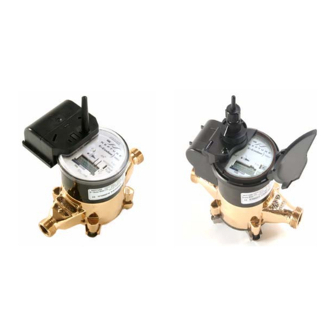
Neptune TRICON E Product manual

TRICON®/E/E2/E3 Transmitter
Installation and Maintenance Guide


TRICON®/E/E2/E3 Transmitter
Installation and Maintenance Guide

Copyright
This manual is an unpublished work and contains the trade secrets and
confidential information of Neptune Technology Group Inc., which are not to be
divulged to third parties and may not be reproduced or transmitted in whole or
part, in any form or by any means, electronic or mechanical for any purpose,
without the express written permission of Neptune Technology Group Inc.
All rights to designs or inventions disclosed herein, including the right to
manufacture, are reserved to Neptune Technology Group Inc.
The information contained in this document is subject to change without notice.
Neptune reserves the right to change the product specifications at any time
without incurring any obligations.
Trademarks Used in This Manual
The following are registered trademarks of Neptune Technology Group Inc.:
lE-CODER
lE-CODER)R900i
lE-CODER)R450i
lProCoder
lProCoder)R900i
lR900
lTRICON
Other brands or product names are the trademarks or registered trademarks of
their respective holders.
FCC Notice
This device complies with Part 15 of the FCC Rules. Operation is subject to the
following two conditions: (1) this device may not cause harmful interference, and
(2) this device must accept any interference received, including interference that
may cause undesired operation.
NOTE: This equipment has been tested and found to comply with the limits for a
Class B digital device, pursuant to Part 15 of the FCC Rules. These limits are
designed to provide reasonable protection against harmful interference in a
residential installation. This equipment generates, uses, and can radiate radio
frequency energy and, if not installed and used in accordance with the
instructions, may cause harmful interference to radio communications.
However, there is no guarantee that interference will not occur in a particular
installation. If this equipment does cause harmful interference to radio or
television reception, which can be determined by turning the equipment off and
on, the user is encouraged to try to correct the interference by one or more of
the following measures:

lReorient or relocate the receiving antenna.
lIncrease the separation between the equipment and receiver.
lConnect the equipment into an outlet on a circuit different from that to which
the receiver is connected.
lConsult the dealer or an experienced radio / TV technician for help.
RF Exposure Information
This equipment complies with the FCC RF radiation requirements for
uncontrolled environments. To maintain compliance with these requirements,
the antenna and any radiating elements should be installed to ensure that a
minimum separation distance of 20 cm is maintained from the general
population.
Professional Installation
In accordance with section 15.203 of the FCC rules and regulations, the MIU
must be professionally installed by trained meter installers.
Changes or modifications not expressly approved by the party responsible for
compliance could void the user's authority to operate the equipment.
Industry Canada (IC) Statements
Section 8.4 of RSS-GEN
This device complies with Industry Canada License-exempt RSS standard(s).
Operation is subject to the following two conditions:
lThis device may not cause harmful interference.
lThis device must accept any interference received, including interference that
may cause undesired operation.
Cet appareil est conforme aux normes RSS exonérées de licence d'Industrie
Canada. L'opération est soumise aux deux conditions suivantes: 1) cet appareil
ne doit pas provoquer d'interférence, et 2) cet appareil doit accepter toute
interférence, y compris les interférences pouvant entraîner un fonctionnement
indésirable de l'appareil.
Section 8.3 of RSS-GEN
Under Industry Canada regulations, this radio transmitter may only operate
using an antenna of a type and maximum (or lesser) gain approved for the
transmitter by Industry Canada. To reduce potential radio interference to other
users, the antenna type and its gain should be so chosen that the equivalent
isotropically radiated power (e.i.r.p.) is not more than that necessary for
successful communication.
This radio transmitter IC: 4171B-L900M has been approved by Industry Canada
to operate with the antenna types listed below with the maximum permissible

gain and required antenna impedance for each antenna type indicated.
Antenna types not included in this list, having a gain greater than the maximum
gain indicated for that type, are strictly prohibited for use with this device.
lMaximum permissible gain of +1 dBi and required impedance of 75 ohm.
lApproved Antenna types:
lR900®Pit Antenna, part number 12527-XXX.
lHigh Gain R900®Pit Antenna, part number 13586-XXX.
lR900®Wall Antenna, part number 13717-000.
lWire monopole, part number 12641-XXX.
En vertu de la réglementation d'Industrie Canada, cet émetteur radio ne peut
fonctionner qu'avec une antenne d'un type et un gain maximal (ou inférieur)
approuvé pour l'émetteur par Industrie Canada. Pour réduire les interférences
radio potentielles avec d'autres utilisateurs, le type d'antenne et son gain
devraient être choisis de manière à ce que la puissance rayonnée
isotropiquement équivalente (e.i.r.p.) ne soit pas supérieure à celle nécessaire à
une communication.
Cet émetteur radio IC: 4171B-L900M a été approuvé par Industrie Canada pour
fonctionner avec les types d'antennes énumérés ci-dessous avec le gain maximal
admissible et l'impédance d'antenne requise pour chaque type d'antenne
indiqué. Les types d'antenne non inclus dans cette liste, ayant un gain supérieur
au gain maximal indiqué pour ce type, sont strictement interdits pour être
utilisés avec ce périphérique.
lGain maximal admissible de +1 dBi et impédance requise de 75 ohms.
lTypes d'antenne approuvé
lAntenne de puits R900®, numéro de pièce 12527-XXX
lAntenne de puits à gain élevé R900®, référence 13586-XXX
lAntenne murale R900®, numéro d'article 13717-00
lFil monopôle, numéro d'article 12641-XXX
TRICON®/E/E2/E3 Transmitter
Installation and Maintenance Guide
Literature No. IM TRICON /E/E2/E3 05.2020
Part No. 13505-011
Neptune Technology Group Inc.
1600 Alabama Highway 229
Tallassee, AL 36078
Tel: (800) 633-8754
Fax: (334) 283-7293
Copyright © 2015 - 2020
Neptune Technology Group Inc.
All Rights Reserved.

Contents
Chapter 1: Product Description 1
Transmitter Styles 1
Digital Pulse 1
Analog 4-20mA 1
Usage 2
Chapter 2: Specifications 3
3
Environmental Conditions
Electrical Specifications (TRICON®/E3 Model) 3
Performance Data 5
Chapter 3: Installing the Transmitter 9
Tools and Materials 9
Preparation 9
Inspection and Storage 9
Safety and Preliminary Checks 9
Installation 10
Wiring the Transmitter 10
Testing the Wires 13
Final Assembly 13
Mounting the Transmitter 13
Chapter 4: Maintaining the TRICON®
System 15
Troubleshooting 15
Contact Information 15
By Phone 15
By Email 16
Glossary 17
Index 19
TRICON®E/E2/E3 Installation and Maintenance Guide vii

This page intentionally left blank.
viii TRICON®E/E2/E3 Installation and Maintenance Guide
Contents

This page intentionally left blank.
xTRICON®E/E2/E3 Installation and Maintenance Guide
Figures

Tables
3
4
4
5
5
6
6
7
8
8
12
Table 1 – Pulse Outputs (over 0-70° C Operating Temperature)
Table 2 – 4-20mA Model (Over 0-50° C Operating Temperature )
Table 3 – HF and UP / DN Models (Over 0-70° C Operating Temperature)
Table 4 – All Models Absolute Limits*
Table 5 – T-10® Disc Meters
Table 6 – T-8 Disc Meters
Table 7 – Trident® Turbine (TT) Meters
Table 8 – High Performance Turbine (HPT) Meters
Table 9 – Compound Meters
Table 10 – 4”, 6”, 8”, and 10” HP PROTECTUS® III Turbine Elements Performance Specifications
Table 11 – TRICON® E/E2/E3 Wiring Codes
Table 12 – Troubleshooting the TRICON®15
TRICON®E/E2/E3 Installation and Maintenance Guide xi

This page intentionally left blank.
xii TRICON®E/E2/E3 Installation and Maintenance Guide
Tables

TRICON®E/E2/E3 Installation and Maintenance Guide 1
Chapter 1: Product Description
The TRICON®/E/E2/E3 Transmitter provides an electronic interface to Neptune®water
meters, enabling customers to monitor their water usage and control various processes
based on that usage.
The TRICON transmitter is available in two styles:
lDigital Pulse.
lAnalog 4-20mA.
The TRICON/E3 Transmitter is not intended for pit applications.
Transmitter Styles
This section describes the two different TRICON transmitter styles.
Digital Pulse
The original Digital Pulse model is a three-terminal transmitter that outputs electrical pulses
at a rate corresponding to the rate of flow through the meter. It requires 12-24VDC operating
power and is intended for use in applications requiring only a digital signal.
The TRICON/E2 and TRICON/E3 Digital Pulse models are five-terminal transmitters that have
the same features as the original Digital Pulse model, plus two additional terminals (High
Resolution Output and Count Direction) for connection to a high-speed, bi-directional
counter. It requires 12-24VDC operating power, and is intended for use in applications
requiring a high resolution digital signal.
Neptune produces the Digital Pulse model TRICON/E transmitters in only two styles for use
with ALL Neptune disc meters or ALL Neptune turbine meters, respectively:
lDisc.
lTurbine.
However, the Analog 4-20mA model TRICON/E transmitters are manufactured specifically for
the size and type of meter with which they should be used. For this reason, take special care
to ensure that you have the proper Analog 4-20mA model TRICON/E required for your
application. Contact Neptune for technical assistance.
Analog 4-20mA
The Analog 4-20mA model is a five-terminal transmitter that has the same features as the
original Digital Pulse model, plus two additional terminals for a 4-20mA output that is
proportional to the rate of flow through the meter. It requires 24VDC operating power, and is
intended for use in applications requiring analog and digital signals.

Usage
All TRICON transmitter models are designed to be mounted between the meter maincase
and a totalizing register, and they do not affect the normal operation of either the meter or
the register. When used with a SmartTrol®controller or other third-party instrumentation
equipment, both the Digital Pulse and Analog models allow monitoring and controlling
complex metering systems.
2 TRICON®E/E2/E3 Installation and Maintenance Guide
Chapter 1: Product Description

TRICON®E/E2/E3 Installation and Maintenance Guide 3
Chapter 2: Specifications
This chapter provides the electrical specifications and the performance data for all models of
the TRICON®transmitter.
The TRICON/E3 is not submersible. Neptune does not recommend installing the
TRICON/E3 in a pit environment.
Environmental Conditions
lOperating Temperature: 32° to +158° F (0° to +70° C)
lStorage Temperature: –40° to +185° F (–40° to +85° C)
lOperating Humidity: 0 to 95% RH, non-condensing
Electrical Specifications (TRICON®/E3 Model)
The following tables define the electrical specifications for the TRICON/E3 model.
Parameter Description Minimum Typical Maximum Units
Vol Low Digital Pulse Output Voltage N/A 0.4 N/A V
Voh High Digital Pulse Output Voltage 8.5 VDCIN–1.0V 12 V
Iol Current @ Vol N/A –10 N/A mA
Ioh Current @ Voh N/A +10 N/A mA
*trl-h Output Rise Time N/A N/A 2 uS
*tfh-l Output Fall Time N/A N/A 2 uS
Table 1 – Pulse Outputs (over 0-70° C Operating Temperature)
*Measured with RL=2.4KΩ and CL=50pF.

Parameter Description Minimum Typical Maximum Units
Vcc Power Supply Voltage 22.5 N/A 26.5 V
IS Power Supply Current 20 N/A 80 mA
RLLoop Resistance 0 N/A 600 Ω
Gain Scaling Accuracy N/A N/A 0.5 %FS
Zero Offset Accuracy N/A N/A 0.2 %FS
Vol Low Digital Pulse Output Voltage N/A 0.4 N/A V
Voh High Digital Pulse Output Voltage 8.5 N/A 12 V
Iol Current @ Vol N/A –10 N/A mA
Ioh Current @ Voh N/A 10 N/A mA
*trl-h Output Rise Time N/A N/A 2 uS
*tfh-l Output Fall Time N/A N/A 2 uS
Table 2 – 4-20mA Model (Over 0-50° C Operating Temperature )
*Measured with RL=2.4KΩ and CL=50pF
Parameter Description Minimum Typical Maximum Units
Vcc Power Supply Voltage 11.5 N/A 26.5 V
IS Power Supply Current 20 N/A 50 mA
Vol Low Digital Pulse Output
Voltage
0 N/A N/A V
Voh High Digital Pulse Output
Voltage
N/A 24 26.5 V
Iol Current @ Vol –1.0 N/A N/A A
Ioh Current @ Voh N/A 0.04 +1.0 W/Voh A
*trl-h Output Rise Time N/A N/A 2 uS
*tfh-l Output Fall Time N/A N/A 2 uS
Table 3 – HF and UP / DN Models (Over 0-70° C Operating Temperature)
*Measured with RL=2.4KΩ and CL=50pF
4 TRICON®E/E2/E3 Installation and Maintenance Guide
Chapter 2: Specifications

Parameter Description Minimum Maximum Units
T (op) Operating Temperature 0 85 °C
T (stg) Storage Temperature –40 85 °C
Vcc Power Supply Voltage –30 30 V
RLOutput Load (pulse output) 1200 N/A KΩ
Iout Output Current (pulse output) N/A 10 mA
Table 4 – All Models Absolute Limits*
*These limits cannot be exceeded without possible damage.
Performance Data
The following tables define the performance data for all TRICON models.
Meter
Size
(In)
Maximum
Flow Rate
(gpm)
Maximum
Continuous Flow
Rate (gpm)
Minimum
Flow Rate
(gpm)
Number of
Pulses per
Gallon*
Pulse Output
@ Maximum
Flow Rate (Hz)*
Flow Range of
4-20MA
Output (gpm)
⅝ 20 10 ¼ 578.10 192.70 0–20
¾ 30 15 ½ 322.60 161.30 0–30
1 50 25 ¾ 150.80 125.67 0–50
1½ 100 50 1½ 67.57 112.62 0–100
2 160 80 2 37.30 100.00 0–160
Table 5 – T-10® Disc Meters
*For the High Resolution Output of TRICON/E2 transmitters, multiply these values by 36, and for the
TRICON/E3, multiply by 40.
TRICON®E/E2/E3 Installation and Maintenance Guide 5
Chapter 2: Specifications

Meter
Size
(In)
Maximum
Flow Rate
(gpm)
Maximum
Continuous
Flow Rate
(gpm)
Minimum Flow
Rate (gpm)
Number of
Pulses per
Gallon*
Pulse Output @
Maximum Flow
Rate (Hz)*
Flow Range of 4-
20MA Output
(gpm)
⅝ 20 10 ¼ 473.60 157.87 0–24.411
¾ 30 15 ½ 329.14 164.57 0–29.40
1 50 25 ¾ 126.55 105.46 0–59.581
1½ 100 50 1½ 47.86 79.77 0–141.181
2 160 80 2 25.60 68.27 0–234.371
Table 6 – T-8 Disc Meters
Meter Size (In)
Maximum
Continuous
Flow Rate
(gpm)
Minimum
Flow Rate
(gpm)
Number of
Pulses per
Gallon*
Pulse Output @
Maximum Flow
Rate (Hz)*
Flow Range of
4-20MA
Output (gpm)
2 200 3 4.6080 15.36 0–200
3 450 5 2.8900 21.68 0–450
4 1,000 10 1.5900 26.50 0–1,000
6 2,000 20 0.4640 15.47 0–2,000
8 (through S/N 31918014) 3,500 35 0.2493 14.54 0–3,500
8 (from S/N 31918274) 3,500 35 0.2253 13.14 0–3,873
10 (through S/N 31919282) 5,500 50 0.1600 14.67 0–5,500
10 (from S/N 31919300) 5,500 50 0.1472 13.49 0–5,981
*For the High Resolution Output of TRICON/E2 transmitters, multiply these values by 36, and for the
TRICON/E3, multiply by 40.
1T-8 disc meters are no longer manufactured, so all TRICON/E transmitters manufactured for disc meters are
the T-10 type. In most cases, the newer T-10 meter chamber is smaller than its corresponding T-8 meter
chamber, which results in the TRICON/E having a theoretical “Flow Rate at 20mA Output” that is greater than
the Maximum Flow Rate allowed for the meter. This means that the T-10 type TRICON/E running on a
T-8 meter will never actually reach the 20mA output level during normal operation. The calculated flow rate
required to produce a 20mA output is a reference for calibrating the 4-20mA receiving instrument.
Table 7 – Trident® Turbine (TT) Meters
*For the High Resolution Output of the TRICON/E2 transmitters, multiply these values by 9 and for the
TRICON/E3, multiply these values by 10.
6 TRICON®E/E2/E3 Installation and Maintenance Guide
Chapter 2: Specifications

Meter Size (In)
Maximum
Continuous
Flow Rate
(gpm)
Minimum Flow
Rate (gpm)
Number of Pulses per
Gallon*
Pulse Output @
Maximum Flow
Rate (Hz)*
Flow Range of
4-20MA
Output (gpm)
1½ 160 4 6.09500 16.25 0–160
2 200 4 6.09500 20.32 0–200
3 450 5 11.20000 84.00 0–450
4 1,200 10 7.55600 151.1 0–1,200
6 2,500 20 0.72730 30.30 0–3,000
8 4,000 35 0.75560 50.37 0–4,000
10 6,500 50 0.75560 81.86 0–6,500
12 8,000 120 0.75560 100.75 0–8,000
16 13,500 200 0.07556 17.00 0–13,500
20 22,000 300 0.07556 27.71 0–22,000
Table 8 – High Performance Turbine (HPT) Meters
*For the High Resolution Output of the TRICON/E2 transmitters, multiply these values by 9 and for the
TRICON/E3, multiply these values by 10.
TRICON®E/E2/E3 Installation and Maintenance Guide 7
Chapter 2: Specifications

Compound Meter* Size and Type Turbine Element Disc Element
3” TRU/FLO 3” TT ⅝” T-10
4” TRU/FLO 4” TT ¾” T-10
6” TRU/FLO 6” TT T-10
2” HP TRU/FLO 2” HPT ⅝” T-10
4” PROTECTUS III 4” TT 1” T-10
6” PROTECTUS III 6” TT 1½” T-10
8” PROTECTUS III 8” TT 2” T-10
10” PROTECTUS III 10” TT 2” T-10
4” HP PROTECTUS III 11” T-10
6” HP PROTECTUS III 11½” T-10
8” HP PROTECTUS III 12” T-10
10” HP PROTECTUS III 12” T-10
Table 9 – Compound Meters
*For TRICON/E Performance Specifications of Compound Meters, refer to the specification information of
each respective meter element.
1Refer to the following table for the performance specifications of the 4”, 6”, 8”, and 10” HP PROTECTUS III
Turbine Elements.
Meter Size (In) Maximum Continuous
Flow Rate (gpm)
Number of Pulses
per Gallon*
Pulse Output @
Maximum Flow Rate
(Hz)1
Flow Range of
4-20MA Output
(gpm)
4 1,200 7.5560 151.2 0–1,200
6 2,500 0.7556 37.78 0–2,888
8 4,000 0.6095 40.63 0–4,959
10 6,500 0.5333 57.78 0–9,209
Table 10 – 4”, 6”, 8”, and 10” HP PROTECTUS®
III Turbine Elements Performance Specifications
*For the High Resolution Output of the TRICON/E2 transmitters, multiply these values by 9 and for the
TRICON/E3, multiply these values by 10.
1Note: This table is based on mounting the HPT TRICON/E3 on the same size HP PROTECTUS III Turbine
Element.
8 TRICON®E/E2/E3 Installation and Maintenance Guide
Chapter 2: Specifications
Other manuals for TRICON E
2
This manual suits for next models
2
Table of contents
Other Neptune Transmitter manuals
Popular Transmitter manuals by other brands

R.V.R. Elettronica
R.V.R. Elettronica TEX3500LCD user manual

Omnitronic
Omnitronic TM-100 user manual

Inovonics
Inovonics EN1216 installation instructions

Xanboo
Xanboo XBX200 user manual

Endress+Hauser
Endress+Hauser Liquisys M CLM 223 operating instructions

Technical Materiel Corporation
Technical Materiel Corporation GPT-10K Technical manual