Artillian 1RMTB Operating instructions

1 of 7
INSTALLATION & OWNER’S MANUAL
Rev. A, 04/30/2020 p/n: IM-1RMTB
The contents of this envelope are the property of the owner. Leave with the owner when installation is complete.
ARTILLIAN ROPS MOUNTED TOOL BAR
P/N: 1RMTB
Approximate Installation Time
Experienced Dealer Technician – 15 Minutes
Average Dealer Technician – 25 Minutes
Do-It-Yourself – 45 Minutes
Approximate Product Specifications
Mounting Bar Width: 42 inches
Weight: 9.76 lbs. (not including accessories)
Capacity: 100 lbs. (including accessories)
The Artillian ROPS Mounted Tool Bar is an innovative system for attaching
accessories to your 2-Post tractor ROPS. It attaches to most rectangular
ROPS profiles in minutes. At 42” wide, it adjusts to fit many different ROPS
widths, without overhanging the rear tires on sub-compact models. Simple,
yet elegant mounting brackets provide limitless adjustability,
accommodating nearly any ROPS angle in either direction.
The proprietary Cam Lever Latching feature found on the many optional
accessories allows for installation and removal of a given accessory in
seconds.
CAUTION Do not exceed the rated capacity for the Tool Bar or its accessories.
Doing so may result in damage to the Tool Bar and will void the warranty.

2 of 7
This kit is designed to accommodate many
sizes and shapes of vehicle ROPS (Roll-Over
Protective Structures). Per the illustrations on
this page, the brackets may face inward or
outward, and may be attached to the inside or
outside face of your ROPS.
Before installation, hold a ROPS bracket up to
the vehicle ROPS and determine the desired
orientation of the bracket. Some considerations
are: ROPS width, ROPS angle, features on
ROPS (ex.: lights, hinges, etc.), and the width of
the user’s implement (s).
It is the user’s responsibility to ensure that
installation of this product does not affect the
functionality of the vehicle ROPS or any other
safety feature of the vehicle. Failure to do so
may result in injury or death.
1. Figure 1 shows a ROPS bracket mounted to the
inside surface of a vehicle ROPS with the bar
mounting surface facing outwards. The bracket can
be flipped so that the bar mounting surface is
facing inwards.
2. Figure 2 shows a ROPS bracket mounted to the
outside surface of a vehicle ROPS with the bar
mounting surface facing inwards. The bracket can
be flipped so that the bar mounting surface is
facing outwards.
3. Figure 3 shows a full-width illustration of ROPS
brackets mounted to the outside surface of a ROPS
with the bar mounting surfaces facing inwards. The
ROPS brackets could also be mounted to the
inside surface of the ROPS (not shown) or flipped
so that the bar mounting surfaces are facing
outwards (not shown).
4. Figure 4 shows a completed installation on an
angled ROPS with the ROPS brackets mounted to
the inside surface of the ROPS. The ROPS
brackets could also be mounted to the outside
surface of the ROPS (not shown).
Fig. 1 (Bracket on inside of ROPS, facing outwards)
Fig. 2 (Bracket on outside of ROPS, facing inwards)
Fig. 4 (Angled ROPS, Brackets shown inside of ROPS)
Fig. 3 (Brackets shown outside of ROPS)
MOUNTING CONFIGURATION OVERVIEW
WARNING

3 of 7
KIT INSTALLATION
1. Park the vehicle on a flat, level surface.
2. Once a mounting configuration has been decided
upon, make a temporary mark of some kind on the
ROPS tubing for locating where to fasten the
ROPS brackets. It is recommended that you take
measurements off of a common feature on the
ROPS so that the brackets will be in line with each
other.
3. Cut the supplied 4-inch long piece of adhesive
backed foam rubber in half. Per figures 3 and 4,
adhere one of the 2-inch long pieces of foam
rubber to the face of the ROPS bracket that will be
against the vehicle ROPS. Select either the inside
or outside surface. Position the foam rubber
between the 4 guide notches provided in the
bracket. Repeat for second bracket.
In order to accommodate various sized ROPS profiles,
two different lengths of U-bolt have been provided.
Please select the most appropriate size for your ROPS
and discard the other two.
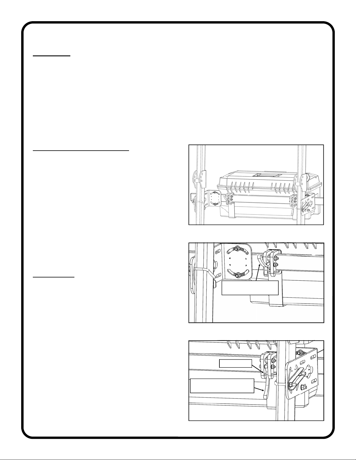
4. See figures 4a, 4b, and 4c. Attach the ROPS
bracket to the ROPS with the bent flange facing
rearward of the vehicle, using one U-bolt, one U-
bolt clamp, and 2 locknuts. The U-bolt clamp
should sit flat on the outside face of the ROPS
bracket. The U-bolt should be rotated in the curved
slots in the ROPS bracket so that the legs of the U-
bolt contact each side of the ROPS tube. Leave
locknuts loose, but snug. Repeat for the second
ROPS bracket.
5. Using a level and/or a tape measure, confirm that
the straightness is good and the desired height was
achieved for both brackets. The mounting bar/tube
from this kit may be used along with a level to
make sure the two brackets are even. Tighten all 4
locknuts in an alternating pattern. NOTE: It is
recommended to use a C-clamp to clamp the
ROPS bracket to the ROPS tube prior to tightening
the fasteners. This helps to prevent bracket rotation
while tightening.
TIP: If it is anticipated that very heavy accessories
(exceeding 50 lbs.) will be used on this mounting
bar, then it is suggested to orient the mounting
brackets with a slight upward pitch to
accommodate any sagging or settling that may
occur due to the weight.
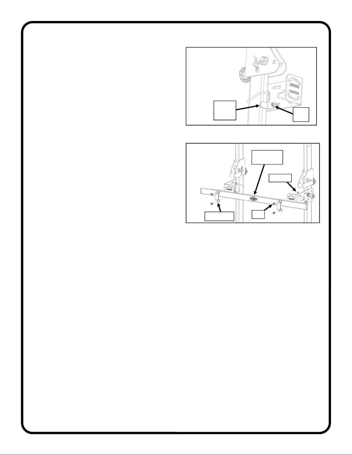
Fig. 3 (Adhere foam rubber to one surface)
Fig. 4c (U-bolt clamp fully assembled)
Fig. 4a (Example of bracket assembly)
Fig. 4b (Orientation of U-bolt clamp)
In this example, the foam
will be on the inside
surface of the bracket
Flat surfaces
against each other
U-bolt clamp
Inside
surface
Outside
surface
U-bolt
clamp
Guide
notches

4 of 7
KIT INSTALLATION
6. Per fig. 6, install the ROPS stabilizer bracket using
one bolt and one locknut as shown. Make sure the
bracket is tight up against the ROPS tubing before
tightening the bolt in the slot. It is recommended to
use a C-clamp to clamp the stabilizer bracket to the
ROPS tube prior to tightening the fastener.
7. Attach the mounting bar to the ROPS brackets,
oriented so the Artillian logo is away from the seat
as shown in fig. 7. Use a tube clamp, two bolts, and
two locknuts per bracket. Center the mounting bar
to the ROPS and tighten bolts.
8. Check the mounting bar for levelness. Adjust if
necessary. Fig. 6 (Install ROPS stabilizer bracket)
Bolt
head
ROPS
stabilizer
bracket
Fig. 7 (Attach mounting bar)
Logo on
mounting bar
Locknut
Tube clamp Bolt

5 of 7
Fig. 1 (example of attaching a tool box)
ATTACHING ACCESSORIES:
1. Figure 1 shows an example of a toolbox installed
on a Tool Bar.
2. To install an accessory, have both cam levers
rotated UP, then place onto the Tool Bar. See fig.
2.
3. To secure the accessory to the mounting bar,
rotate both cam levers DOWN until they cam over.
See fig. 3.
NOTE: The accessory can be locked to the Tool Bar by
inserting a padlock through the holes in the mounting bracket
where shown.
4. To remove an accessory, rotate both cam levers
UP and lift the unit off of the Tool Bar.
OPERATION
1. Due to the excessive vibrations generated by a tractor,
the ROPS Mounted Tool Bar fasteners may loosen up
over time. It is recommended that the fasteners are
checked and retightened, as required, regularly.
2. Depending on space availability on a give ROPS, a
second Tool Bar can be added to allow for even more
accessories to be attached at a time.
FEATURES AND OPERATION
Fig. 2 (cam lever in the open position)
Fig. 3 (cam lever in the closed position)
rotate both cam levers up
to install an accessory
padlock holes
rotate both cam levers down
to secure the accessory
FEATURES
The Artillian ROPS Mounted Tool Bar allows for one or more Artillian ROPS Mounted Accessories to be
attached to the vehicle ROPS. Additional Tool Bars allow for additional accessories.
The innovation of the design is that any of the compatible accessories can be installed or removed from the Tool
Bar in seconds, without the use of tools.
One job may require a toolbox filled with various hand tools. Another might necessitate a tool rack holding
assorted long-handle yard tools or maybe a chainsaw mount and fuel can holder.
With the effortless installation and removal of each accessory, you won’t waste any time setting up your tractor
to carry the specific tool required for the job!

6 of 7
MOUNTING BAR ASSEMBLY
P/N: 8SV-113-00186 (QTY.: ONE)
ROPS BRACKET ASSEMBLY
P/N: 8SV-110-00069 (QTY.: ONE)
TUBE CLAMP ASSEMBLY
P/N: 8SV-110-00068 (QTY.: ONE)
U-BOLT CLAMP PLATE
P/N: 8SV-SM-01592 (QTY.: ONE)
ROPS STABILIZER BRACKET ASSEMBLY
P/N: 8SV-110-00073 (QTY.: ONE)
SERVICE PARTS:
1/2” V-GROOVE WEATHERSEAL
P/N: 9SV-PR20-10 (QTY.: 10 FEET)
FOAM SEAL, 1” X 1/8”
P/N: 9SV-PR39-5 (QTY.: 5 FEET)
PLASTIC TREE CLIPS
P/N: 9SV-CP01 (QTY.: 12)

7 of 7
ROPS MOUNTED TOOLBOX, SMALL
P/N: 1RMTBXS
ROPS MOUNTED TOOLBOX, LARGE
P/N: 1RMTBXL
ROPS MOUNTED TOOL RACK
P/N: 1RMTRK
ROPS MOUNTED CHAINSAW MOUNT
P/N: 1RMCSM
(chainsaw shown for illustration purposes)
ROPS MOUNTED FUEL CAN HOLDER
P/N: 1RMFCH
ROPS MOUNTED TOOL BASKET
P/N: 1RMTBSK
AVAILABLE ACCESSORIES:
MORE ACCESSORIES COMING SOON!
Table of contents
Popular Tractor Accessories manuals by other brands

Grouser Products
Grouser Products 770HD Steiger Quad 550 Owner's manual and parts book

Land Pride
Land Pride SPL0548 Operator's manual

MK Martin
MK Martin Pulsar Wing Operator's & parts manual

Raven
Raven AccuBoom installation manual

Meyer
Meyer Power Box 58 Operation and maintenance manual

Toro
Toro Greensmaster 04654 Series Operator's manual