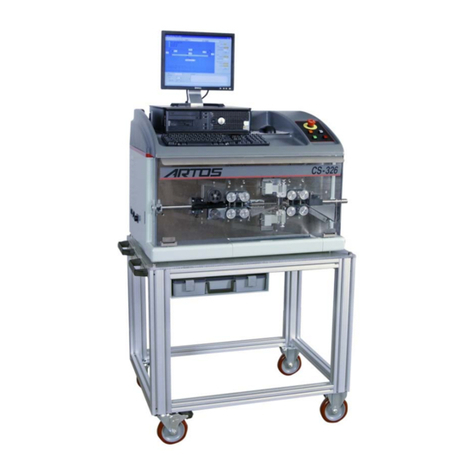
Artos CS-327 User manual

1
Machine Model CS-327 Owners Manual
P/N 6-119886A Rev. 3.18 Date 09 Sept 2015
Artos Engineering Company
21605 Gateway Court
Brookfield, WI 53045
Phone 262-252-4545 Fax 262-252-4544
www.artosnet.com

2
TABLE OF CONTENTS
CUSTOMER SAFETY NOTICE............................................................................6
SAFETY INTERLOCKS..........................................................................................................................6
SAFETY WARNINGS!! ..........................................................................................................................7
MACHINE DESCRIPTION....................................................................................8
SPECIFICATIONS...................................................................................................................................8
INSTALLATION....................................................................................................9
Machine power up...................................................................................................................................11
OPERATION.......................................................................................................12
RUN SCREEN ....................................................................................................12
PUSH BUTTON LEGENDS..................................................................................................................14
GETTING STARTED ............................................................................................................................14
WIRE AND STRIP LENGTH SETTINGS............................................................................................16
STRIP STROKE (FULL OR PARTIAL)...............................................................................................16
STRIP METHOD SELECTION.............................................................................................................17
STRIP DIAMETER................................................................................................................................18
PROGRAM QUANTITIES....................................................................................................................18
TotalParts..........................................................................................................................................18
BatchParts .........................................................................................................................................18
CYCLE MODES ....................................................................................................................................18
AutoMode..........................................................................................................................................19
SingleMode........................................................................................................................................19
StepMode...........................................................................................................................................19
Speed%..............................................................................................................................................19
SETTINGS ..........................................................................................................19
PART PROPERTIES..............................................................................................................................19
Processtab.........................................................................................................................................19
LabelTab............................................................................................................................................20
OtherTab ...........................................................................................................................................21
WIRE PROPERTIES..............................................................................................................................22
PrimaryStripDiameter.....................................................................................................................23
SecondaryStripDiameter.................................................................................................................23
StripVelocity......................................................................................................................................23
StripAcceleration. .............................................................................................................................23
CutterWayBack ................................................................................................................................24
CutterReady ......................................................................................................................................24
CutterHome.......................................................................................................................................24
StripDelay..........................................................................................................................................24

3
FeedRate............................................................................................................................................24
Acceleration. ......................................................................................................................................24
OutfeedRollerStop ...........................................................................................................................24
FeedRollerPressure .........................................................................................................................25
WireLengthCalibration....................................................................................................................25
SlipSensitivity. ..................................................................................................................................26
MaxSlug ..............................................................................................................................................26
Color ...................................................................................................................................................26
Largewirecheckbox .........................................................................................................................26
FILE MANAGEMENT .........................................................................................27
CREATING AND EDITING PARTS....................................................................................................27
CREATING AND EDITING JOB PROGRAMS...................................................................................27
Creating a New Job Program..............................................................................................................28
Programming for Batch Mode ............................................................................................................29
Programming for Harness Mode.........................................................................................................29
FOLDERS...............................................................................................................................................30
DATA STORAGE IN CS327.................................................................................................................31
Data Backup........................................................................................................................................31
Data Restore........................................................................................................................................32
Data Export.........................................................................................................................................33
Data Import.........................................................................................................................................35
DATA ORGANIZER .............................................................................................................................36
Selecting items....................................................................................................................................36
Copying or moving items....................................................................................................................36
Deleting items.....................................................................................................................................38
Using the Library for wires, instead of the current folder...................................................................38
Using a common folder on a network drive........................................................................................39
MAIN MENU SELECTIONS................................................................................39
File ......................................................................................................................................................39
View....................................................................................................................................................40
Maintenance.......................................................................................................................................41
Controller ...........................................................................................................................................41
Tools ...................................................................................................................................................42
Help .....................................................................................................................................................42
BAR CODE SCANNING.....................................................................................42
Part Selection..........................................................................................................................................42
Material Validation.................................................................................................................................44
CONFIGURATION................................................................................................46
ProgrammingMachineOptions .......................................................................................................46
StripModeProgramming .................................................................................................................47
PreProcessConfiguration ................................................................................................................48

4
PostProcessConfiguration...............................................................................................................49
LabelConfiguration...........................................................................................................................50
LANGUAGE CONFIGURATION AND TRANSLATION.....................................51
Configuring the machine for a language.................................................................................................51
Translated text files.............................................................................................................................55
changing the translation for a text string in the software........................................................................55
OPTIONS............................................................................................................58
PREPROCESS PROGRAMMING ......................................................................64
SLITTING (slitter)..................................................................................................................................64
SlitterSetUp ......................................................................................................................................64
WINDOW STRIPPING (SLITTER+PERF) ..........................................................................................65
SLITTER TOOLING SET UP................................................................................................................66
WIRE MARKING..................................................................................................................................67
MarkerPhysicalSetup ......................................................................................................................67
HOT STAMP MARKER (HOT STAMP)..............................................................................................67
WM6 ...................................................................................................................................................68
ContinuousStamp(EvenStep).........................................................................................................68
2‐EndStamp.......................................................................................................................................68
TableStamping(Individual).............................................................................................................69
HOT STAMP MARKER (CONTINUOUS II).......................................................................................69
INK JET PRINTING (INK JET)............................................................................................................70
UV CURING LIGHT OR SPARK TESTER (STEADY-ON/OTHER).................................................75
BRADY WIRE WRAPTOR LABELER (WRAPTOR).........................................................................75
LABEL PRINTING OPTION ...............................................................................76
CONFIGURING THE COMPUTER......................................................................................................76
CONFURING THE LINK TO THE NICELABEL SOFTWARE .........................................................77
SELECTING THE PRINTER ................................................................................................................79
CREATING A LABEL...........................................................................................................................80
PRINT TIMING......................................................................................................................................87
Variable List........................................................................................................................................87
BLADE REPLACEMENT....................................................................................89
STRIPPING BLADE REPLACEMENT................................................................................................90
CUTOFF BLADE REPLACEMENT.....................................................................................................90
INSTALLING THE PINCH BLADE.....................................................................................................91
PINCH BLADE CALIBRATION..........................................................................................................92
INSTALLING THE CARBIDE BLADE ...............................................................................................93
BLADE SELECTION ..........................................................................................95
MAINTENANCE..................................................................................................95
PREVENTIVE MAINTENANCE..........................................................................................................95

5
DailyMaintenace ...............................................................................................................................95
Semi‐AnnualMaintenance................................................................................................................95
CABINET ACCESS...............................................................................................................................96
wire feed BELT ADJUSTMENTS .........................................................................................................97
Feeddrivebeltsreplacementandadjustment................................................................................97
CUTTERHEAD CALIBRATION AND BELT REPLACEMENT .......................................................99
Mechanical – Motor Index Mark Alignment......................................................................................99
Procedure to install the cutterhead timing belt..................................................................................101
Settingthe“ServoReferenceCalibration” .......................................................................................102
FEED TUBE ADJUSTMENTS............................................................................................................104
Feedtubelowerpositionadjustment............................................................................................104
TROUBLESHOOTING GUIDE .........................................................................105
SLUG NOT PULLING OFF THE WIRE.............................................................................................105
INCONSISTANT STRIP LENGTH.....................................................................................................110
WIRE LENGTH NOT CONSISTANT ................................................................................................112
LEAD END STRIP FOLDS BACK.....................................................................................................112
SYSTEM LOGIN / PASSWORD.......................................................................113
WindowsLogin................................................................................................................................113
MachineSoftwareLogin .................................................................................................................114
AddingUsersAndPasswords........................................................................................................116
SettingPasswordAccessLevels .....................................................................................................116
MACHINE START UP SEQUENCE..................................................................117
I/O STATES ......................................................................................................119
MACHINE STATES LISTING............................................................................................................120
DIGITAL I/O........................................................................................................................................122
SERVO MOTOR POSTION................................................................................................................124
IMAJE TEST.....................................................................................................124
APPENDIX........................................................................................................130
APPENDIX A.......................................................................................................................................130
GuardInterlockandEmergencyStopSystem...............................................................................130
APPENDIX B.......................................................................................................................................131
Troubleshootingtheservodrive...................................................................................................131
APPENDIX C.......................................................................................................................................132
PushButtonFunctionDescription.................................................................................................132

6
ARTOS CS 327
CUSTOMER SAFETYNOTICE
The CS 327 as supplied to you must only be used with all the guards and safety
devices in place and secure to meet the intended requirements. The safety
interlocks must not be tampered with or overridden in any way. Should any
guards, interlock, or other safety device be found to be damaged or non-operative
the machine cannot be used until appropriate repairs have been effected.
All safety guards and interlocks should be tested daily or at the beginning of each shift change. It
is recommended that these checks be documented.
SAFETY INTERLOCKS
FRONT GUARD: Opening the front guard will stop the machine and display the warning
“Front Guard Open”. The same message will appear if the MASTER START is press with the
guard open.
SCRAP DRAWER: Opening the scrap drawer will stop the machine and display the warning
“Scrap Drawer Open”. The same message will appear if the MASTER START is press with the
scrap drawer open.
SEE APPENDIX “A” FOR MORE DETAILS OF THE GUARD INTERLOCK AND
EMERGENCY STOP SYSTEM.
All electrical enclosures must be kept closed and secured. Only authorized persons with
appropriate training should access these enclosures. In the event that it is required to access
electrical enclosures with main power on, only persons properly trained and familiar with
acceptable Safety Regulations may do so.
When performing routine maintenance, adjusting, or cleaning the machine must be electrically
isolated from the power supply.
Above all else “Think Safety” and insure that the machine is in fact safe.

7
SAFETY WARNINGS!!
The following explicit directions apply in this manual. Do not disregard these
directions.
WARNING: personal injury may occur-Do not disregard.
CAUTION: Equipment damage may occur.
NOTE: Inconvenience only if disregarded. No immediate danger
of damage or personal injury.
WARNING!! The CS 327 Uses sharp cutting tools to perform its function. Great
care must be taken to protect the operator and others from harm.
WARNING!!
Never attempt in any way to operate this machine with the guards
removed.
Never attempt in any way to operate this machine with the guards open.
Never attempt in any way to disable the safety guard switches.

8
MACHINE DESCRIPTION
The Artos CS 327 is a compact, electronic control linear feed wire processing machine that is designed
to process a wide variety of cables. The CS 327 can accept flat or round material. A rugged machine
intended for long continuous operation, the CS 327 uses a precise electronic measuring system and the
latest in wire processing technology to quickly and accurately process your material.
SPECIFICATIONS
A. WIRE CUT LENGTHS:
Maximum: 12598 inches (320M)
Minimum: .25” (6,4 mm)
B. WIRE SIZE: (WIRE DEPENDENT)
The copper diameter this machine can cut is dependent on the stranding of the copper.
The cutterhead can produce 2000lbs of cutting force. Low strand counts mean that it
takes more force therefore the wire diameters are smaller as compared to a finely
stranded cable.
Two blade cutterhead
Machine with standard wire guide kit
Maximum OD 1.18” (30.0mm)
The maximum ID (inside diameter) of the guides is 1.25 inches (31.8mm)
Minimum: 12 AWG (3.3mm2), Wires that are more stiff like steel cable
can go to smaller sizes.
The minimum ID of the guides is 0.12 inches (3.05mm)
Machine with large wire guide kit
Maximum OD 1.43” (36.2mm)
The maximum ID of the guides is 1.50 inches (38.1mm)
Minimum: 12 AWG (3.3mm2) , Wires that are more stiff like steel cable
can go to smaller sizes.
The minimum ID of the guides is 0.12 inches (3.05mm)
Three blade cutterhead.
Maximum OD Up to 0.80 inches (20mm), Larger diameters may be possible
depending on depending on the wire.
Minimum: 12 AWG (3.3mm2) , Wires that are more stiff like steel cable can go to
smaller sizes.
C. STRIPLENGTHS:
Two blade cutter head
Maximum: 39"(999 mm) Leading end 39”(999 mm).
Three blade cutter head
Maximum: 1.3"(33 mm) Leading end 1.3”(33 mm).

9
D. MACHINE SIZE:
Length: 50” (1520 mm)
Width: 24” (605 mm)
Height: 57” (1453 mm)
E. MACHINE WEIGHT:
2200 lbs. (998 Kg.) packed weight
F. Electrical
230±10% VAC 47-63 Hz. Single Phase 3 kW (Nominal)
Protection Against Electric Shock: Grounded metal enclosure
G. Environmental
Temperature: Operating 0°C to +45°C, Storage -25°C to +55°C
Relative Humidity: 30% to 95% (non- condensing)
Altitude: Up to 4000 ft. MSL (1200 m MSL)
Sound Level: 54 dbA quiescent 73 dbA automatic cycle
Other:This equipment is designed for normal operation in a dry location where it is not likely to be
subjected to drip, splash or spray of water or other liquid.
INSTALLATION
A. Once you have received your CS 327,un-crate the unit and make a thorough inspection to determine
if any loss of contents, or damage, has occurred during shipping. Any shipping related damage must
be reported to the carrier immediately.
B. This equipment is designed for normal operation in a dry location where it is not likely to be subjected
to drip, splash or spray of water or other liquids. Select a suitable location for which allows adequate
perimeter access for maintenance.
C. Un-pack the LCD screen and mount it on the monitor bracket.
D. Un-pack the keyboard and mouse. Along with the computer you will find the manual and operating
system disks for the PC. (Store these items along with the carton in a safe location. In the event of a
computer failure it will be necessary to return it along with the operating system disks in the original
carton.) Set the keyboard and mouse on the operator station if they are not already installed. The two
devices route into the operator station and plug into the monitor.
E. The PC is placed in the compartment at the left end of the lower cabinet. Use the provided foot to
stand the PC vertically. Connect the cables as marked and slide it in place.

10
F. The connecting cables are routed through the tube and in along the mounting bracket. The cables are
joined just inside cabinet. See below,
Monitor, Keyboard and Mouse PC compartment
Monitor, mouse, and keyboard cable connections
G. Connect to a 220 50/60/1 electrical supply.
CAUTION: Before connecting the main electrical supply, ensure that the voltage and frequency are
within the specified limits for the nominal values shown on the name plate.
H. Set-up and attach optional equipment in the appropriate locations in relation to the main unit.
I. Connect an air supply of 80 PSI nominal Volume 10 CFM
The CS 327 is ready to start.

11
MACHINE POWER UP
Turn on the main switch on the back of the electrical cabinet. Press the button on the UPS. It will beep
when it is on. The Operator interface (PC) will boot-up and initialize the Windows and ARTOS CS 327
GUI programs.
If communications are working these two screens will appear and automatically close.
Close the guard and release the E-Stop button. Pressing the Master Start button will energize the power
system in the machine. Pressing the Cycle Start will initialize the start up sequence (a series of beeps will
start). The Feed system will open and the cutterhead will reference. When the start up reference is
complete, the beeping will stop. Click the check boxes to clear the dialog windows.
Note: When shutting the machine down follow these steps.
Close the CS 327 software
Shut down the computer by clicking start - shutdown.
When the computer is off turn off power to the machine
Press the button on the UPS to turn off the UPS.

12
OPERATION
The following information will allow you to put your CS 327 into production in a minimum amount of time.
Additional features and maintenance functions will be discussed in future sections
RUN SCREEN
The RUN SCREEN is the primary screen the operator will use to run and program the CS 327.
SCREEN LEGEND
THE FOLLOWING ITEM NUMBERS WILL BE REFERRED TO THOUGHOUT THIS
MANUAL
1. Enter – Wire length tip to tip. (See page 16 )
14 15 16
13
17/18
10
11
20
1
4
5 6
9 2 3
7
8 19
24
25
26
27

13
2. Enter – Strip length (typical both ends) (See page 16)
3. Enter - Strip pull length (values the same or larger then Strip Length will remove the strip. Values smaller
will leave the strip on by the differential) (See page 16)
4. Enter - Blade opening distance corresponds with approximate conductor diameter. (See page 18)
5. Wire: This will open the Wire Properties window where the wire characteristics are set up (see page 22)
6. Drop down menu to select previous qualified wires. Selection will be displayed in adjacent window.
7. Mode: Allows selection of Auto, Single, or Step modes of operation. (see page18)
8. This allows the control of the global speed of the machine in the selected mode. (5 to 100%)
9. This selects the stripping method: Short mode, Center Stripping, and Double Strip.
10. Total Parts/ / Programmed: Enter – Total number of parts desired. (See page 18)
11. Batch Parts/ / Programmed: Enter – Number of parts desired in a batch. (See page 18)
12. Click on Ruler Icon to switch between Inch and Metric measuring mode.
13. Click on the Wire Icon to set up or modify the part properties.(see page 19)
14. Drop down menu to select previous programmed parts. Selection will be displayed in adjacent
window.
15. Click on the Wire Array Icon to set up or modify the Job properties.(see page 27)
16. Drop down menu to select previous programmed Jobs.
17. Click on the Folder Icon to set up or modify data folders.(see page 30)
18. Drop down menu to select previous established folders. Selection will be displayed in adjacent
window.
19. Operator instructions programmed with the part.
20. Shows current and real time production rates.
21. Saves all changes made to current programs.
22. Opens Maintenance I/O statues screen (Including machine states, I/O data, and servo data)
23. Opens the Machine Configuration Window. (See page46)
24. Preprocess-Marking / Slitting ### indicates a preprocess is selected (see page 64)

14
25. Remake. As you make batches of parts you may need to make an extra part. By pressing the remake
button, one part extra will be made for the current batch. When running in job/batch mode, this
button will be inactive as the machine changes over from one part to the next. The button is always
inactive for in Job/Harness mode.
26. Bar code scan. For selecting part name by scanning a bar code.
27. Material. Opens a window for verifying the wire via bar code scan.
PUSH BUTTON LEGENDS
MASTER START: Activates the main contactor. Must be on for any action to occur.
CYCLE START: Activates the cycle function that is selected. AUTO, SINGLE, or STEP MODES
CYCLE STOP: Will stop the current cycle at the end of the cycle.
FEED BELTS: Will alternately open and close the feed system. (Master Start must be on)
EMERGENCY STOP (The red mushroom button) will stop all motion immediately.
GETTING STARTED
To put your CS 327 into production follow these easy steps:
1. Insure the proper blades are installed in the cutterhead. (See 89)
2. Select the measuring mode desired, inch or metric, by clicking on “Ruler Icon” at the top of the
screen (#12). The selection will toggle between inch and metric.
3. Click on “Wire” (#5) to setup a new wire or click on Drop down button (#6) to select from
existing wires. For more information configuring the wire properties see section WIRE
PROPERTIES page 22.
4. Click on Drop down button (#14) to select part, select MDI (Manual Data Input).
5. Enter data in #’s 1, 2, and 3. Select Preprocess if required.
6. Now to save this information as a Part to be used again click on the “Part Icon” (#13) the Parts
Properties dialog window will appear. Click on the “New” button and enter the name you wish to
use in the window that appears. Click on the green check box. For more information on
configuring the part properties see section PART PROPERTIES page 19.
Master Cycle Cycle Belts Jog Feed Emergency
Start Start Stop Open/ Close Stop

15
7. Insert the proper size wire guides. (See document ” CS-327 Guide Selection.pdf”)
A. Wire straightened guides. Use the proper guide based on wire size before the wire
straightener . (Not shown)
B. Select infeed guide based on wire size.(2 places}
C. Select feed tube based on wire size
D. Select outfeed guide based on wire size.
E. Select discharge guide based on wire size
B
C D E

16
8. To open the feed belts press the “Feed Rollers” button.
The feed belt tension is set via the regulator on the front panel.
40 to 60 PSI is a nominal pressure to start with. The
general rule is to use the min pressure need to do the job.
Excessive pressure or insufficient pressure will accelerate
belt wear.
The EMERGENCY STOP button must be released, the guard closed and MASTER
START pressed before the Feed Roller button will function To release the
Emergency Stop button rotate the button clockwise until the button pops up.
9. Insert the wire though the guides and position the leading end of the wire at the
left end of the infeed belts about 2” on to the belt. Jog the feed about 3 inches
twice then jog it to the end of the feed tube. Do not feed it into the outfeed guide. The CS 327 will
feed a predetermined length of wire and cut it off to qualify the end of the wire for first piece
accuracy. This piece must be free to drop in the scrap tray .This will happen each time the Feed
belts are opened and closed or the Emergency Stop button is used.
Close the feed belts by pressing the “MasterStart and Feed Rollers” buttons.
10. Select the “Single” mode (#7) and press the “Cycle Start” Button. This will produce one sample
piece. Examine the part, make necessary adjustments, and repeat as necessary. When results are
satisfactory select “Auto” mode press “Cycle Start” to commence production.
Pieces made In Single or Step are not counted as part of the total quantity
WIRE AND STRIP LENGTH SETTINGS
Wire (#1) and strip (#2) length are entered by double clicking on the appropriate window; the field
will turn blue, enter the desired values and press ENTER.
STRIP STROKE (FULL OR PARTIAL)
Strip Stroke (#3) length is entered by double clicking on the appropriate window. The field will turn
blue, enter the desired values and press ENTER. If the value is the same as or longer than the strip
length the slug will be pulled of completely. If the value is less than the strip length value the slug will
C D
E
A
&B
SPARE BLADES
LOWER MACHINE DRAWER

17
only be that far leaving it on the end of the wire. Elasticity of the insulation may determine the pull
required to break the slug free from the wire.
STRIP METHOD SELECTION
The strip method option (#9) allows the ability to select several types of stripping methods.
Short Wire This is for wires that need to have both ends stripped but are too short to reach the
out feed belts. In this mode the machine strips a length of insulation off the lead that is the
total length of both the lead and tail strip. It then slides down the wire the length of insulation
that should be left in the center of the wire. Then it cuts the wire off to the correct length.
NOTE: It is very important that the body length of insulation is able to slide on the
conductor. For insulation lengths that cannot be slide along the wire without damage or
slipping the wire in the belts this mode will not work. You may need to enter values
program values different on the screen to get the measured values you need. This is
because of the flexibility of various insulations.
Lead /Tail Center Stripping This mode will allow you to program a Center (window) strip
near the end of the wire.
To accomplish a leading or trailing Center Strip select one or both in the upper left corner of
the screen.
Then program the over all wire length and the “T” and “L” strip lengths as usual.
Enter the desired center strip length value in the “C” field (Center Strip) and the distance
between the end of the wire and the near edge of the center strip in the “O” field (Off Set).
Above is an example of a wire with a .25 in center strip 5 inches from the end of the wire.
C O
O C

18
NOTE: It is very important that the body length of insulation is able to slide on the
conductor. If the insulation is difficult to slide, it may be necessary to adjust values to
accomplish a center strip successfully.
Lead / Tail Double Strip gives the ability to strip a wire that requires a 2 step strip such as
coax cable. When this is selected the wire image will change. Entry fields for the window strip
position and length will appear. The normal strip values are the Primary values. (smaller
diameter) The added windows are the Secondary values. (larger diameter) The Strip
Diameter for the Secondary strip is found in the Wires Properties (#5) The order of the
stripping, inner conductor first or outer conductor first, is selectable through the Machine
Configuration (#23)
STRIP DIAMETER
Strip Diameter is entered by double clicking on the appropriate window (#4), the field will turn blue,
enter the desired values and press ENTER. (Secondary Strip Diameter is found in Wire Properties)
PROGRAM QUANTITIES
TotalParts
Click on “Programmed” window, Enter the total number of pieces to be produced. Press Enter. The
value in “Complete” window will increase until it matches Programmed the value. Then the CS
327 will stop cycling.
BatchParts
Click on “Programmed” window, Enter the total number of pieces to be in a batch. Press Enter. The
value in “Complete” window will increase until it matches the Programmed value. Then the CS 327
will stop cycling.
CYCLE MODES
NOTE: The MASTER START button must be on to activate any cycle mode.

19
All the machine cycling functions are controlled by the CYCLE START button. To select which
mode is used (AUTO, SINGLE, or STEP) click on the drop down button (#7) and select.
AutoMode
When the AUTO mode is selected the CS 327 will start producing the desired wires in the quantities
programmed in the Total Parts field, divided into the amounts programmed in the Batch Parts field
using the selected Batch Control mode.
SingleMode
When the SINGLE mode is selected the CS 327 will produce one complete wire. This is usually
used to check the quality of the piece. This piece is not counted by the CS 327.
StepMode
When the STEP mode is selected the CS 327 will produce one wire at a time progressing through the
process step by step. With each press of the CYCLE START button the process will advance one
step. This will allow the operator to view each step of the process. This piece is not counted by the CS
327.
Speed%
The value in these windows is the percentage of the total speeds the machine will run in the selected
mode.
SETTINGS
PART PROPERTIES
Processtab
Preprocess dropdown Select the name of the pre-process you would like to perform on the wire (see section
PRE PROCESS PROGRAMMING page 64). Leave blank if no pre-process.
Adjust pre-process to fit – If this box is checked the software will automatically change the programmed
lengths of the pre-process so it will fit on the programmed length of wire. For example you may have
programmed a Hot Stamp pre-process that has a mark 6 inches from each end of the wire. Then you

20
programmed a length of wire to be 10 inches. The software will automatically change the mark to be 4 inches
from each end of the wire so it will fit.
Post Process drop down Select the name of the post process device connected to the machine (see
section Post Process Config page 49)
Auto Outfeed – If this box is checked the machine will feed each part completely clear of the machine before
it start processing the next part. This is sometimes necessary depending on the type of post process that is
selected or in the way in is necessary for the operator to handle the parts. Having this box checked will reduce
the parts per hour.
LabelTab
The label feature can only be used if the Nicelabel software and printer are installed on the machine. See
section Label printing option (page 76) for more details.
Click the browse button . Select the name of that label and click the green check. For information on
creating and editing labels see section CREATING A LABEL on page80.
Select the Print Timing you want to use,
User Select (The label will print whenever you click on the label icon )
At each part completion (print a label after each part)
At batch completion (print a label after each batch)
At program completion (print a label after special stripping)
For more information see section PRINT TIMING on page 87.
Table of contents
Other Artos Computer Hardware manuals
Popular Computer Hardware manuals by other brands

Asus
Asus USB-BT211 Mini Bluetooth Dongle user manual

Panasonic
Panasonic UP0KG8D Specification sheet

Freescale Semiconductor
Freescale Semiconductor MC68HC908MR16 datasheet

Mylex
Mylex eXtremeRAID 1100 installation guide

Tektronix
Tektronix Socket 7 TMS109A instruction manual

StarTech.com
StarTech.com 1P3FFCB-USB-SERIAL quick start guide