AS MOTOR AS 600 MultiPro User manual

Operator's Manual
Device carrier and attachments
AS600MultiPro
From serial number: 036320070001
Issued: 19 January 2021, V1.0
en-Translation of the Original Operator's Manual

Notes on the operating manual
2
dummy
Notes on the operating manual
Dear customer,
Congratulations on your purchase. You have acquired a reli-
able quality product by ”AS-Motor Germany”.
This product has been manufactured according to modern
manufacturing methods and comprehensive quality assur-
ance measures. Only when you are satisfied with your device
have we attained our goal.
These operating instructions contain important information to
help you avoid hazards and to increase the reliability and the
life span of the device.
Read the operator’s manual before using the
device. Share this operator’s manual and the oper-
ator’s manual of the engine manufacturer with
other users of the device.
Contact
If you have questions about your device, please contact your
customer service.
For international AS partners, please see: www.as‑mo-
tor.com.
Device data
Please fill in all data referring to your device. When ordering
spare parts, provide your dealer with the serial and engine
numbers.
Serial number (see manufacturer’s certificate or type plate):
Engine number:
Date of purchase:
Address of dealer:
Intended use
The device is only intended for operation with attachments
that have been approved by "AS-Motor Germany".
Observe the information on intended use in the chapter of the
respective attachment.
Any other use exceeding this purpose is inadmissible.
Follow the instructions in the chapter Maintenance of the at-
tachment carrier and the respective attachment. Otherwise,
operational safety is endangered.
The user of the device is responsible for accidents or dam-
age that can happen to other persons or their property!
In particular, the device must not be used
– Observe the information in the chapter of the respective at-
tachment
– for transporting people, loads or towing trailers.
– as drive unit for work tools and any type of tool sets that
are not authorised by “AS-Motor Germany”.
The device is not licensed for driving on public roads.

Contents
Notes on the operating manual.................................. 2
Contact ......................................................................... 2
Device data................................................................... 2
Intended use................................................................. 2
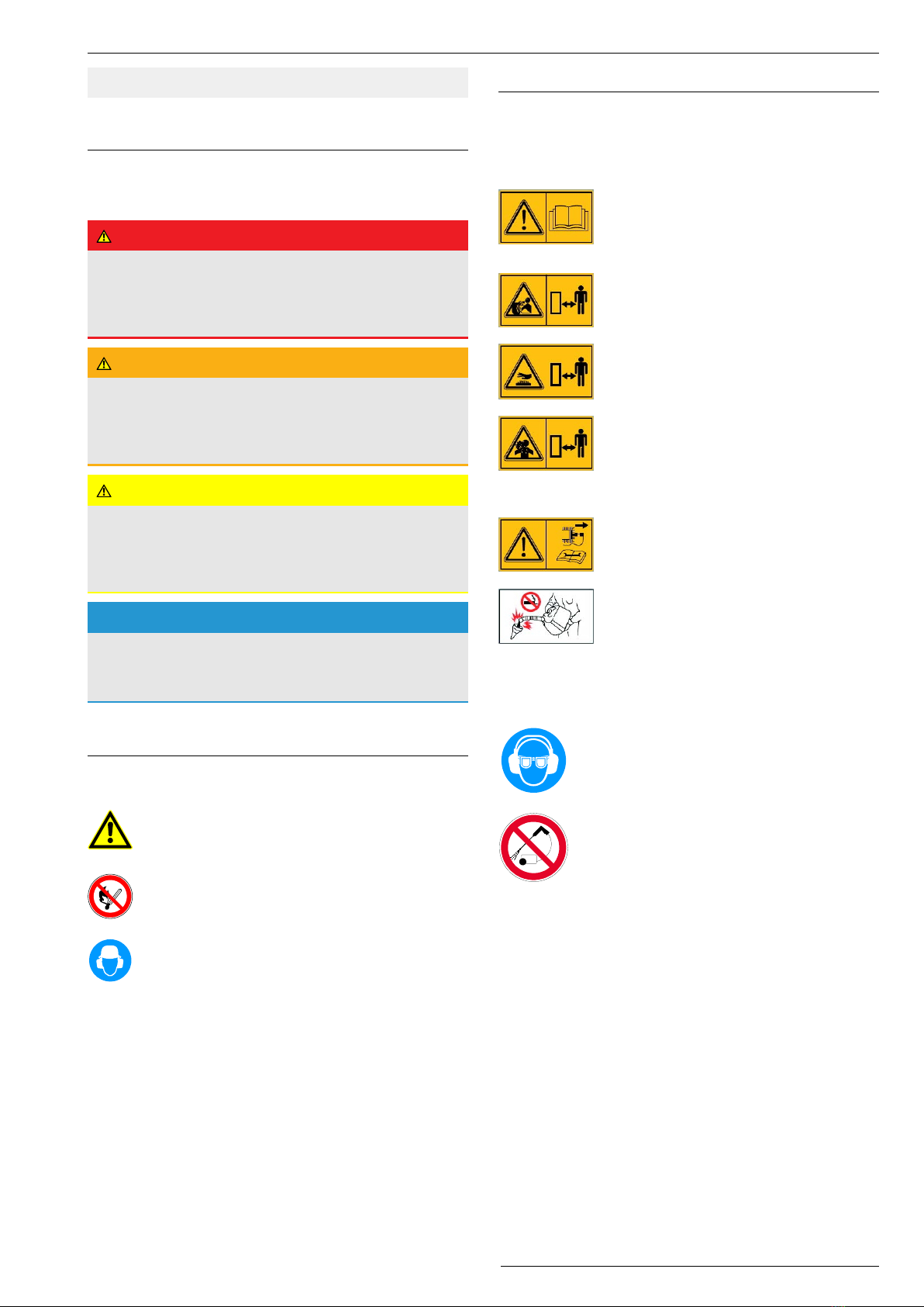
Explanation of the symbols........................................ 5
Warnings...................................................................... 5
Symbols in the instructions........................................... 5
Signs on the device...................................................... 5
Safety instructions ...................................................... 6
Get informed!................................................................ 6
User restrictions and hours of operation....................... 6
Safe handling of fuel..................................................... 6
Check the device prior to use....................................... 7
Use of attachments....................................................... 7
Danger area.................................................................. 7
Use caution during operation........................................ 8
Before you start working............................................... 8
Caution during working................................................. 9
Caution when mowing slopes....................................... 9
When work is completed.............................................. 10
Use caution during maintenance and repair................. 10
Device description....................................................... 11
Control elements ......................................................... 12
Information on how to work........................................ 13
Prior to starting............................................................ 13
Fuel............................................................................... 13
Tanking up.................................................................... 13
Checking the engine oil level........................................ 13
Starting......................................................................... 14
Starting the device........................................................ 14
Setting the maximum permissible engine speed.......... 14
Driving .......................................................................... 14
Driving.......................................................................... 14
Reverse gear................................................................ 15
Steering and turning..................................................... 15
Pushing......................................................................... 15
Switching the working tool on and off........................... 15
Switching off and parking........................................... 15
Mounting the attachments.......................................... 16
Preparing the attachment carrier for the attachment.... 16
Mounting the attachment.............................................. 16
Dismounting the attachment......................................... 16
Attachment cutter bar ................................................. 17
Intended use (cutter bar).............................................. 17
Safety instructions (cutter bar)...................................... 17
Information on mowing................................................. 17
Device description ESM cutter bar G90900102........... 18
Device description LOSI cutter bar G90900103........... 18
Setting the cutting height.............................................. 19
Attachment flail bar G90900104 ................................. 19
Intended use................................................................. 19
Signs on the device...................................................... 19
Safety instructions (attachment flail bar)...................... 20
Information on mowing................................................. 20
Device description........................................................ 20
Adjusting cutting height................................................ 20
Locking steerable front wheel....................................... 20
Attachment sweeping brush G90900105................... 21
Intended use................................................................. 21
Signs on the device...................................................... 21
Safety instructions (sweeping brush)............................ 21
Information on how to work.......................................... 21
Device description........................................................ 22
Sweeping brush side adjustment.................................. 22
Adjusting the contact pressure of the brush................. 22
Transport...................................................................... 23
Loading......................................................................... 23
Unloading the device.................................................... 24
Maintenance................................................................. 25
Maintenance and cleaning position.............................. 25
Maintenance overview.................................................. 26
Cleaning the device carrier and attachment................. 29
General inspection........................................................ 29
Maintenance device carrier......................................... 29
Hydrostatic transmission.............................................. 29
Maintaining the engine................................................. 29
Checking the engine oil level........................................ 29
Checking the spark plugs............................................. 29
Maintaining the air filter................................................ 30
Checking the drive........................................................ 30
Checking coupling for working tool............................... 30
Checking the parking brake.......................................... 30
Assembly...................................................................... 31
Maintenance ESM cutter bar....................................... 31
Cleaning the cutter bar................................................. 31
General inspection........................................................ 31
Checking the blade....................................................... 31
Servicing the cutter bar................................................. 31
Checking the blade driver............................................. 32
Adjusting the blade guide plates................................... 32
Resharpening the blades.............................................. 32
Changing the blades..................................................... 32
Checking coupling for working tool............................... 32
Checking the oil level of the blade drive....................... 32
Grease lubrication........................................................ 33
Assembly...................................................................... 33
3
Contents

Maintenance LOSI cutter bar...................................... 33
Cleaning the cutter bar................................................. 33
General inspection........................................................ 33
Checking the blade....................................................... 33
Servicing the cutter bar................................................. 33
Checking, adjusting and greasing the blade drivers..... 34
Setting the lower blade guide....................................... 34
Changing the blades..................................................... 34
Checking coupling for working tool............................... 34
Checking the oil level of the blade drive....................... 34
Grease lubrication........................................................ 34
Assembly...................................................................... 35
Maintenance attachment flail bar............................... 35
Cleaning the flail bar..................................................... 35
General inspection........................................................ 35
Grease lubrication........................................................ 36
Checking the blade and flail shaft................................. 36
Assembly...................................................................... 37
Maintenance attachment sweeping brush ................ 37
Cleaning the device...................................................... 37
General inspection........................................................ 37
Grease lubrication........................................................ 37
Checking the brushes................................................... 38
Changing the brushes.................................................. 38
Assembly...................................................................... 38
Storage ......................................................................... 39
Storing the device......................................................... 39
Longer storage............................................................. 39
Restarting..................................................................... 39
Spare parts................................................................... 39
Wear parts.................................................................... 39
Disposal........................................................................ 39
Warranty....................................................................... 39
Troubleshooting .......................................................... 40
Accessories.................................................................. 43
Technical data – Device carrier.................................. 44
Technical data - ESM cutter bar................................. 45
Technical data - LOSI cutter bar................................. 46
Technical data - Attachment flail cutter bar.............. 47
Technical data - Attachment sweeping brush .......... 48
Declaration of conformity........................................... 49
4
Contents

Explanation of the symbols
5
dummy Inhaltsverzeichnis
Explanation of the symbols
Warnings
In these operating instructions, warning instructions are
marked with signal words. The signal words are used to in-
dicate the following hazards and potential consequences.
Danger
Imminent danger
Indicates an imminently hazardous situation with a high
level of risk that, if not avoided, will result in minor or
moderate injury.
Warning
Hazardous situation
Indicates a possibly hazardous situation with a medium
level of risk that, if not avoided, could result in minor or
moderate injury.
Caution
Hazardous situation
Indicates a possibly hazardous situation with a low level
of risk that, if not avoided, could result in minor or moder-
ate injury.
Notice
Danger of property damage
Indicates a possible risk of damage of the device and its
surroundings.
Symbols in the instructions
In these operating instructions, the following symbols are
used to denote special dangers.
Warning.
These symbols denote special dangers.
Prohibition sign.
These symbols denote inadmissible procedures.
Directive sign.
These symbols denote required protective meas-
ures.
Symbols in the text
1. A numbered text requests you to act or shows a process
sequence.
ðAn indented arrow marks the result of a step.
ðAn arrow that is not indented refers to the result of a se-
quence of actions.
Notice: An additional piece of information is marked by the
work "Notice" written in bold letters.
Signs on the device
The following signs are attached to the device to provide a
reminder that during use of the device, you will have to be
careful and attentive:
Working with the device requires extreme
cautiousness.
Read the operating instructions before you
use the device.
Danger of bursting while tires are inflated.
Observe the admissible tire pressure (see
Technical data).
Hot surfaces or components. Do not touch
the engine or the silencer.
The device generates poisonous exhaust
fumes as soon as the engine is running.
Some of these gases are odourless and in-
visible. Never let the engine run in closed
rooms.
Prior to any repair and maintenance work,
pull off the spark plug connector.
Explosion hazard!
Keep the fuel away from ignition sources
and do not smoke while handling the
device.
Observe the safety instructions regarding
the fuel!
Noise is causing health problems. Use per-
sonal ear protection to avoid hearing damage.
Wear safety glasses.
Do not clean the device with water spray or
high-pressure cleaner!

Safety instructions
6
Type plate
The type plate on the device provides you with informa-
tion on the device type and the technical data.
1 Name and address of the manufacturer
2 Device designation
3 Type designation
4 Rates power output in kW / engine speed
5 Weight
6 Year of manufacture
7 Serial number
8 CE marking
Safety instructions
Get informed!
For your safety, read these operating instructions carefully.
Familiarize yourself with the control elements and the proper
use of the device. Share these operating instructions with
other users of the device.
Have skilled personnel who were trained by AS-Motor show
you the safe handling of the device before you work with it for
the first time.
Get familiar with the device in a wide, open and flat terrain
first.
When working on or adjacent to public roads, observe the
local regulations, if necessary.
On our homepage www.as-motor.com you will find further in-
formation, especially on the ecologically oriented mainten-
ance of green spaces.
User restrictions and hours of operation
Never allow children or persons who are not familiar with the
operator’s manual to use the device. Persons under 18 years
of age may operate the device only under proper supervision.
Local regulations determine the minimum age of the operator
and the operating times.
Unsuitable for operation of the device are persons who
– are under the influence of alcohol, drugs or reaction delay-
ing medications.
– have physical and mental/emotional impairments.
– are tired or sick.
Persons with pace makers must not touch live
parts of the ignition system.
Safe handling of fuel
Fuel is toxic and highly flammable. There is a burn and explo-
sion hazard!
Keep fuel away from ignition sources and do not smoke dur-
ing handling.
Do not inhale fuel vapours, they are dangerous to your
health.
Use gloves and avoid skin contact with the fuel.
Always refuel outdoors when the engine is cold and stopped
completely. When doing so, always use a filler spout or a fun-
nel.
Do not spill any fuel or do not let fuel enter canalisation or
drain away.
When fuel has overflown, do not start the device until the fuel
vapours have evaporated (wipe dry). Move the device away
from the spilled fuel.
Always close the tank cap tightly and do not open it while the
engine is running or the device is still hot.
Empty the fuel only when outdoors. Use the approved con-
tainer for this or run the fuel tank empty.

Safety instructions
7
Store the fuel away from children and keep it in a suitable
container in a dark, cool and dry place.
Never store the device when there is fuel in the tank inside a
building where fuel vapours might come into contact with
open fire or sparks.
Immediately replace the fuel tank or tank cap if they are dam-
aged (authorised service centre).
First aid
When swallowing fuel or inhaling fuel vapours, do not force
vomiting and immediately consult a doctor.
In case of skin contact, immediately wash with water and
soap. Change your soiled clothing as soon as you can.
Measures in case of a fire
In case of a fire, use foam, dry powder extinguisher, or car-
bon dioxide (CO2). Never douse with water!
Check the device prior to use
Prior to use, check the work tools, protection skirt, drive and
fastening parts, cables and cable connections, hoses, hose
connections and containers for proper working condition and
firm seating by visual inspection.
Never use the device with defective or missing protective
devices, covers, protection skirt or bar.
Do not remove, change or override any safety devices or
control elements.
Observe the maintenance instructions (see chapter Mainten-
ance).
Have an authorised service centre check the device if the
work tools do not stop within a few seconds after being
switched off
Use of attachments
Read the chapter of the attachments before attaching and us-
ing the attachment.
Switch off the engine of the attachment carrier before attach-
ing and detaching an attachment.
Prior to each operation, check the device for completeness,
proper function, and cleanliness.
There is a risk of injury when attaching and detaching attach-
ments. Wear protective gloves, safety shoes and use suitable
tools.
Secure the attachment carrier and attachments to prevent
them from rolling away.
Support the attachment carrier and attachments with suitable
aids during mounting and dismounting.
Attach the attachments as described in the chapter Mounting
the attachments.
Switch off the attachment when driving on surfaces other
than the working area.
Danger area
Fig.1:
Within the danger area of the device, there is a risk of injury.
The tool of the attachment cause injuries and objects can be
thrown out. The area in front of and next to the device is es-
pecially dangerous.
On slopes, the device can topple over and slide towards per-
sons or run them over.
Make sure
– that nobody else besides the user is on the work area.
– that people are never positioned in the direction of travel in
front of the device.
– that nobody is positioned on the slope below the device.
– that you have a complete overview of the danger area at all
times.
– that you do not bring your hands and feet close to moving
parts, especially the working tools.

Safety instructions
8
A
B
B
The size of the danger zone depends on the attachment
used.
Attachment Front (A) Side (B)
ESM cutter bar G90900102 10m 5m
LOSI cutter bar G90900103 10m 5m
Attachment flail cutter
G90900104
20m 5m
Attachment sweeping brush
G90900105
50m 5m
Use caution during operation
Danger of injury during motor start
Do not start the engine
– if fuel was spilled.
– in closed or poorly ventilated rooms (danger of poisoning!).
– if there are other persons nearby.
Only start the device when your feet are at a safe distance to
the working tools.
When the engine is started, the device must not be tilted.
Risk of injury when the attachment is running
Switch off the attachment and wait until the attachment stops,
– when you drive on surfaces other than the working area.
Risk of injury when the engine is running
Switch off the engine and wait until the engine and the at-
tachment stop
– before you tilt or transport the device.
– before you step away from the device, even for just a short
time.
– before you adjust the working height.
– before you refuel.
Switch off the engine, wait for the working tools to stop and
remove the spark plug connector
– before you clean or check the device or before you carry
out work on the device.
– before you remove and clear blockages.
Risk of burns
Do not touch the engine or the silencer. These parts become
very hot during operation and you can get burned. If a jumpy
movement occurs, the risk of additional injuries can result.
Before you start working
Personal protective measures
Always wear safety shoes with good grip and
long trousers. Do not work with open sandals
or while shoeless.
Wear safety gloves to protect yourself against
injuries and vibrations.
Noise is causing health problems. Use per-
sonal ear protection to avoid hearing damage.
Wear safety glasses and headgear.
In case of high dust development, wear a dust
mask.
Ask your specialised dealer about suitable protective equip-
ment.
Preparing working area
Examine the working area carefully before working. Remove
rocks, pieces of wood, bones, wires, cords and other objects
that could be thrown away, wound up or whirled around by
the device.
Remove live cables from the working area. These can be
damaged during work and cause an electric shock or short
circuit.

Safety instructions
9
Caution during working
Risk of injury
Risk of injury caused by ejected objects. Never work when
persons, children, pets, or objects are in the danger area.
Keep your hands and feet away from moving and rotating
parts. Keep a distance to the working tools while working with
the device.
Make sure that help can be provided in case of an emer-
gency.
Only work during daylight or with adequate artificial lighting.
Never work in the event of uncertain weather conditions and
risk of lightning.
Be especially careful when working on soft ground, nearby
landfills, ditches, dikes and water edges.
Fig.2:
Avoid mowing damp grass, there is a sliding risk!
Avoid working on slippery working areas.
Be extremely cautious when turning the device round or
pulling it toward you and when moving in reverse.
Always walk slowly!
Never lift or carry the device when the engine is running.
Pay attention to traffic when working close to roads.
Vibrations
When the device is used over a longer period of time, vibra-
tions can cause disturbances in the blood supply of the
hands. A generally accepted usage time cannot be determ-
ined.
– Use gloves.
– Take breaks on time.
Have an authorised service centre check the device
– when the working tool has hit an object.
– if the device starts to vibrate unusually severely.
Working on surfaces with a fire hazard
– Carry a sufficient amount of suitable extinguishing media.
– If the device leans too much to the side, fuel can leak from
the carburetor or the tank. This presents a fire hazard!
– Observe the working area even after working to make sure
that no fire breaks out.
To prevent a fire hazard, always keep the following compon-
ents free of dirt, grass, hay, leaking oil, grease, etc.:
– Engine
– Silencer (manifold, protection, spaces)
– area around the fuel tank
Caution when mowing slopes
Fig.3:
There is a risk of injury during driving on slopes due to tipping
over or sliding.
– Drive on steep terrain only when safe operation can be
guaranteed.
– Do not drive on excessively steep slopes.
– Take suitable precautions on steep slopes, e.g. by using
step irons.
– If possible, always drive across the slope, avoid driving up
or downhill.
– Always make sure that you step safely, use non-slip safety
shoes.
– Be extremely cautious when changing the direction.
– Drive only when the ground is dry and has a good grip.
– When driving on the slope, make sure the steerable front
wheel is locked (if existing).
When facing downhill, the device can roll away. Park the
device on level ground only and secure against rolling away
with the parking brake.

Safety instructions
10
When work is completed
After working, always close the fuel valve.
Prior to leaving the device, wait until the motor comes to a
standstill and pull off the spark plug connector.
After switching it off, let the device cool down for at least 20
minutes before you store it in a dry, closed, sufficiently ventil-
ated room.
Never place the device with petrol in the tank inside a build-
ing where petrol vapours may come into contact with open
flames or sparks.
Secure the attachment carrier and the attachment against un-
authorised use before leaving the device.
Use caution during maintenance and
repair
Only carry out work as described in these operating instruc-
tions. Have an authorised service centre perform all other
work.
Prior to all maintenance work, wait until the engine comes to
a standstill and pull off the spark plug connector.
We explicitly point out that, in accordance with the Product Li-
ability Act, we are not liable for damages that were caused by
our devices if
– worn or damaged parts were not repaired or replaced on
time.
– these damages were caused by improper repair.
– when changing a part, our original parts or parts authorised
by us were not used.
– the repair work was not carried out by an authorised ser-
vice station.
The same applies for spare parts and accessories.

Device description
11
Device description
1
3
5
2
9
64 7
10
11
8
14
12
13
1Support foot
2Oil dipstick
3Frame
4Parking brake
5Ventilation grid
6Starter grip
7Fuel valve
8Choke
9Tank filler spout
10 Air filter
11 Spark plug connector
12 Silencer
13 Type plate
14 PTO shaft

Control elements
12
Control elements
D
A
G
C
F
HB
F
E
Engine stop switch with accelerator lever (A)
Use the engine stop switch with accelerator lever to switch
the ignition off or on and change the engine speed.
0: Engine off / engine cannot be
started.
1: Use the accelerator lever to set
the permissible engine speed (see
Setting the maximum permissible
engine speed)
Rev counter(B)
When the engine is running, the engine speed is displayed.
When the engine is switched off, the operating hours are dis-
played.
Drive speed lever (C)
Use the drive speed lever to select continuously between id-
ling (STOP) and forward and reverse travel.
In idling (STOP), the device does not move.
The further you push the lever forward, the faster the device
moves forward.
The further you pull the lever back, the faster the device
moves backwards.
1
2
3
1: Moving forward
2: STOP: Stopping (idling)
3: Moving in reverse
Safety lever (D)
The safety lever is a guard device.
With the safety lever, you switch the drive
on and off.
The working tool can only be switched on
when the safety lever is actuated. When
you release the safety lever, the drive and
the working tool are switched off.
1
2
STOP (1):
Switching off drive and
working tool
ON (2):
Switch on drive. The
working tool can be
switched on
Clutch lever working tool (E)
With the clutch lever, you switch the working tool on and off.
1
2
STOP (1):
Switch off working tool. Flip the clutch
lever forward.
ON (2):
Switch on working tool. Flip the clutch
lever backward.
Steering arm (F)
Use the two steering arms to control the
direction of travel of the device.
Steering to the right:
press the right lever to-
wards the handlebar.
Steering to the left:
press the left lever to-
wards the handlebar.
Lateral adjustment handlebar(G)
The handlebar can be locked in 3 positions.
1. Press detent lever towards the handlebar.
2. Swivel the handlebar to the side to the desired position.
3. Release the detent lever and engage the handlebar in
the desired position.

Information on how to work
13
Height adjustment of handlebar(H)
The handlebar can be locked in 3 positions.
1. Press detent lever down.
2. Move the handlebar to the desired position.
3. Release the detent lever and engage the handlebar in
the desired position.
Choke (8)
Close the choke during cold start of the
engine.
Open the choke:
Push the lever inwards.
Close the choke:
Push the lever out-
wards.
Fuel valve (7)
2
1
1: Closed
2: Open
Information on how to work
Check the device for completeness, proper function, and
cleanliness before each operation. A dirty ventilation grid
causes overheating of the engine which can result in engine
damage. A dirty protective grid at the silencer poses a fire
hazard.
Frequent engagement and disengagement leads to in-
creased wear of the drive belt and components of the drive.
Especially engaging under load, e.g. in high grass, leads to
overload.
You will find further information on working in the respective
chapters of the attachment tools.
Special information, e.g. on ecological mowing and available
attachments, can be found on our homepage www.as-mo-
tor.com.
Prior to starting
Fuel
As fuel, use unleaded petrol (see operating instructions of the
engine manufacturer).
You can use E10 petrol. Do not store E10 petrol longer than
30 days.
Tanking up
Warning
Fuel is ignited by hot engine parts.
► Prior to filling up, switch off the engine and wait for at
least 20minutes until the engine has cooled down. Ob-
serve the safety instructions regarding the fuel!
Filling up with fuel
1. For filling, use a canister with filler spout or a funnel.
2. Open the canister carefully so that existing excess pres-
sure is slowly reduced.
3. Open the tank cap carefully so that existing excess pres-
sure is slowly reduced and no fuel sprays out.
4. Fill the fuel tank.
5. Tightly close the tank cap again.
Checking the engine oil level
Attention! Prior to each use, check the engine oil level (see
operating instructions of the engine manufacturer).

Starting
14
Starting
Danger
Danger of poisoning due to poisonous exhaust gases.
► Do not operate the engine in closed or insufficiently
ventilated rooms.
► Please observe the safety instruction regarding the
poisoning risk.
Danger
Danger of electric shock from live cables on the working
area. Live cables can be damaged during work and cause
an electric shock or short circuit.
► Make sure that the working area is free of live cables.
Warning
During startup, there is a risk of injury due to the running
working tool.
► Make sure that nobody is in the danger area of the
working tool. Do not tilt the device when starting.
Warning
If after startup the carburetor does not close properly, fuel
will overflow and a fire hazard occurs.
► Close the fuel valve and contact an authorised service
centre.
Starting the device
1. Place the device on even terrain, not in high grass.
2. Open the fuel valve.
3. Plug in the plug connector.
4. With cold start, close the choke.
5. Turn the accelerator lever to medium engine speed.
6. Pull the starter rope slowly out until you feel resistance
and then pull out quickly – engine starts to run.
7. Slowly release the starter rope.
8. Open the choke again.
Setting the maximum permissible engine
speed
The engine speed must be set according to the attachment.
By setting the maximum permissible engine speed
– the specified emissions are complied with.
– a better work result is achieved.
– the strain on the operator and the environment is reduced.
– the stresses on the device are minimized and the service
life of the device is increased.
Use the accelerator lever to set the maximum permissible
speed for the for the attachment in question. The current
speed can be read off the rev counter.
For the maximum permissible engine speeds, see the
chapter "Technical data" of the respective attachment. At-
tachments for which the setting of the maximum permissible
engine speed is particularly important, are additionally
marked with a sign on the device.
Depending on the work task, the engine speed can be further
reduced.
Reducing the engine speed additionally reduces the load on
the for the operator, the environment and the device.
Notice
Damage to the attachment due to the engine speed being
set too high.
► Observe the information of the attachment.
► Set the engine speed to the maximum permissible en-
gine speed (see chapter "Technical data" of the attach-
ment).
Driving
Driving
Warning
Risk of injury caused by unintended movement of the
device.
► Set the speed lever to STOP before operating the
safety lever to prevent unintentional movement of the
device.
Warning
Risk of injury due to driving speed set too high.
► Select a low driving speed before operating the safety
lever, especially when reversing.
► Only drive fast enough to control the machine safely at
all times.
► Always set the speed lever to STOP when stopping.
Use the drive speed lever to select between idling (STOP)
and continuously adjustable forward and reverse speed.
You can set the driving speed before driving or while driving.
The further you push the lever forward, the faster the device
moves forward. The further you pull the lever back, the faster
the device moves backwards.
Adjust the driving speed to the work task and the working
conditions. Always start slowly and only increase the speed if
you can control the device safely at all times.
In case of a hazardous situation, switch off the drive working
tool.
Drive on
1. Select a low speed.
2. Press the safety lever towards the handlebar – device
starts moving.
3. If necessary, adjust the speed.

Switching off and parking
15
Drive off
1. Release the safety lever and set the speed lever to STOP.
Reverse gear
Warning
Risk of injury due to tripping or slipping when driving in re-
verse and when turning.
► Prior to switching on the reverse gear, make sure that
your path is clear of obstacles.
1. Release the drive lever.
2. Set the speed lever to a low reverse speed.
3. Push the safety lever back towards the handlebar –
device starts moving backwards.
Steering and turning
Warning
When the steering lever is operated on a slope, the device
may roll away or move unexpectedly.
► Operate the steering leer carefully on slopes.
► Only operate one steering lever at a time on a slope.
► Release the steering levers when the device rolls away.
In order to steer while driving, a steering clutch is installed for
each drive wheel. When the steering lever is operated, the
steering clutch is disengaged, resulting in a steering move-
ment. The disengaged wheel is free to move and unbraked.
The steering clutch can also be used in reverse.
Steering to the right:
– Pull the right steering lever - the device moves to the right.
Steering to the left:
– Pull the left steering lever - the device moves to the left.
Turning on level ground:
– Pull both steering levers - both wheels are free to move
and unbraked, the device can be moved or turned freely.
Pushing
1. Release the drive lever.
2. Push both steering levers towards the handlebar – device
can be pushed or rolls.
Switching the working tool on and off
Switch on working tool
1. Push the safety lever towards the handlebar.
2. Pull the clutch lever backwards - the working tool starts
up.
Switch off working tool
1. Flip the clutch lever forward or release the safety lever.
Always switch off the working tool when you do not need it,
e.g. when driving outside the working area.
Switching off and parking
Warning
When facing downhill, the device can roll away.
► Park the device on level ground only and secure against
rolling away with the parking brake.
1. Release the drive lever.
2. Set the speed lever to STOP.
3. Turn the engine stop switch to "0".
4. Activate the parking brake.
5. Wait for the engine to stop completely before you step
away from the device.
6. Close the fuel valve.
7. Pull off the plug connector.

Mounting the attachments
16
Mounting the attachments
The attachments are mounted on the stud bolts of the front of
the attachment carrier.
2 3 1 4
Preparing the attachment carrier for the
attachment
The stud bolts(1) can be fitted in two positions on the bolt-on
plate(4). Depending on the position other attachments from
AS-Motor can be fitted.
1. To loosen the stud bolts, screw both nuts(2) onto one
stud bolt.
2. Tighten the nuts against each other (lock).
3. Unscrew the stud bolt with the rear nut.
4. Insert the stud bolt in the appropriate position.
5. Tighten the stud bolt with the front nut as far as it will go.
6. Repeat steps 1-5 with the second stud bolt.
Attachment Inner
position
Outer
position
ESM cutter bar G90900102 - x
LOSI cutter bar G90900103 x -
Attachment flail bar G90900104 x -
Attachment sweeping brush
G90900105
x x
Mounting the attachment
6
5
Notice
Risk of damage due to incorrect mounting of the attach-
ment.
► When mounting, make sure that you do not damage the
threads.
1. Place the attachment carrier on the support leg.
When doing so, ensure the correct height setting. The
coupling flange on the attachment(5) and the bolt-onplate
of the attachment carrier(4) must be at the same height
and parallel to each other.
2. Remove the nuts(2) and the washers(3).
3. Push the attachments with the coupling flange carefully
onto the stud bolts (1).
4. Screw the washers(3) with the nuts(2).
5. When screwing on, make sure that the centring ring(6)
slides into the bolt-on plate(4) and that the coupling
flange(5) lies flat against the bolt-on plate.
The claw coupling slides back when it is screwed on and en-
gages during operation.
Dismounting the attachment
1. Remove the nuts(2) and the washers(3).
2. Remove the attachment.
3. Screw the nuts(2) and the washers(3)onto the stud bolts.

Attachment cutter bar
17
Attachment cutter bar
Intended use (cutter bar)
The device is intended only for cutting grass or similar veget-
ation in well-maintained grounds in agriculture, forestry and
preservation of the countryside that are cut at least once a
year.
The device is only intended for operation with attachment
carriers that have been approved by “AS-Motor Germany”.
Any other use exceeding this purpose is inadmissible.
Observe the information in chapters Maintenance of device
carriers and Attachment. Otherwise, operational safety is en-
dangered.
The user of the device is responsible for accidents or dam-
age that can happen to other persons or their property!
In particular, the device must not be used:
– Observe the instructions in chapter of the device carrier.
– to cut hard objects, stones, rubble, or pieces of wood.
– to trim bushes, hedges, and shrubbery.
– to cut plants in balcony boxes or containers or on roofs.
– as shredder for shredding tree and hedge cuttings.
Safety instructions (cutter bar)
Risk of injury from sharp blades on the cutter bar! Always fit
the protective bar when the cutter bar is not in use.
If the device is used for mowing food or fodder, all parts that
come into contact with it may only be lubricated with oils or
greases that are suitable / approved for this purpose.
Information on mowing
Observe the working instructions in the chapter of the device
carrier.
Set the engine speed to the maximum permissible speed for
the attachment (see chapter “Setting the maximum permiss-
ible engine speed“). Higher speeds result in higher emis-
sions.
Only mow with a sharp and undamaged blade.
Have the blade sharpened regularly (authorised service
centre).
You can obtain a well-maintained area by mowing regularly.
Areas that are not mown regularly, e.g. interspersed with per-
ennial grass, woody shoots, shrubs, etc., cannot be mown
without difficulty.
Adjust the driving speed to the mowing conditions so that the
grass is cut evenly.
Avoid mowing areas where grass has already been cut to
prevent blockages.
Beware! The cutter bar can be damaged by collision with
obstacles.
– Keep a lateral distance from obstacles.
– Do not mow into obstacles.
Remove the clippings after mowing.
Recycle or dispose of the clippings properly or in accordance
with local regulations.
A dirty ventilation grid causes overheating of the engine
which can result in engine damage. A dirty protective grid at
the silencer poses a fire hazard.
Frequent engagement and disengagement leads to in-
creased wear of the drive belt and components of the drive.
Especially engaging under load, e.g. in high grass, leads to
overload.
In order to cut the grass on level ground and lay it down
evenly, we recommend following the mowing patterns shown
above.
In order to cut the grass on the slope and lay it down evenly,
we recommend following the mowing patterns shown above.
or safety reasons, always mow across the slope if possible.
If possible, always turn uphill.
On our homepage www.as-motor.com you will find further in-
formation, especially on the ecologically oriented mainten-
ance of green spaces.

Attachment cutter bar
18
Device description ESM cutter bar
G90900102
9
2
7
7
5
8
3
10
1
6
4
1Blade guard
2Upper blade
3Lower blade
4Cutter bar
5Cover
6Coupling sleeve
7Skids / cutting height adjustment
8Upper blade guide arms
9Lower blade guide arms
10 Cover cap for grease nipple drive lever bearing
Signs on the device (ESM cutter bar)
The following signs are attached to the device to provide a
reminder that during use of the device, you will have to be
careful and attentive:
Working with the device requires extreme
cautiousness.
Read the operating instructions before you
use the device.
The quickly moving blade can cause lift-
threatening injuries or major property dam-
age! Make sure to especially keep hands
and feet away from the blades when the
device is in operation.
Risk of injury from sharp blades! Only re-
move the protective bar for mowing.
Maximum permissible engine speed when
using the attachment.
Set the maximum permissible engine
speed on the accelerator lever.
Device description LOSI cutter bar
G90900103
1
6
2
3
10
11
7
7
8 4
14
12
13
9
5
15
1Blade guard
2Upper blade
3Lower blade
4Cutter bar
5Cover
6Coupling sleeve
7Skids / cutting height adjustment
8Upper blade guide arms
9Head plate lower blade
10 Driver sleeves
11 Adjusting screw upper blade driver
12 Clamping screw of the adjusting screw
13 Screw plug for oil level check
14 Lever for lifting the guide arms
15 Template for adjusting the lower blade guide
Signs on the device (LOSI cutter bar)
The following signs are attached to the device to provide a
reminder that during use of the device, you will have to be
careful and attentive:
Working with the device requires extreme
cautiousness.
Read the operating instructions before you
use the device.
The quickly moving blade can cause lift-
threatening injuries or major property dam-
age! Make sure to especially keep hands
and feet away from the blades when the
device is in operation.
Risk of injury from sharp blades! Only re-
move the protective bar for mowing.
Maximum permissible engine speed when
using the attachment.
Set the maximum permissible engine
speed on the accelerator lever.

Attachment flail bar G90900104
19
Setting the cutting height
Warning
Risk of injury from sharp working tools.
► Only adjust the cutting height when the engine is
switched off.
► Wear protective gloves.
Set the cutting height high enough so that the blade does not
touch the ground even if the terrain is uneven.
Set the cutting height to the same height on both sides to ob-
tain an even cutting pattern.
The adjustment of the cutting height is stepless.
1. Place the device on a level surface.
2. Switch off the engine and wait until the attachment comes
to a standstill.
21
3. Carefully lift the cutter bar.
Place e.g. wooden blocks under the cutter bar at the de-
sired cutting height.
4. Slacken the nuts (1).
5. Swivel the skids(2) until the desired cutting height is
reached.
6. Tighten the nuts(1).
Attachment flail bar G90900104
Intended use
The device is intended only for cutting grass or similar veget-
ation in well-maintained grounds in agriculture, forestry and
preservation of the countryside that are cut at least once a
year. Woody growth must not be older than maximally one
year.
The device is only intended for operation with attachment
carriers that have been approved by “AS-Motor Germany”.
Any other use exceeding this purpose is inadmissible.
Observe the information in chapters Maintenance of device
carriers and Attachment. Otherwise, operational safety is en-
dangered.
The user of the device is responsible for accidents or dam-
age that can happen to other persons or their property!
In particular, the device must not be used:
– Observe the instructions in chapter of the device carrier.
– to cut hard objects, stones, rubble, or pieces of wood.
– to trim bushes, hedges, and shrubbery.
– to cut plants in balcony boxes or containers or on roofs.
– as shredder for shredding tree and hedge cuttings.
Signs on the device
The following signs are attached to the device to provide a
reminder that during use of the device, you will have to be
careful and attentive:
Risk of injury!
Make sure that no one is within the danger
zone of the device. Objects may be ejec-
ted.
The rapidly rotating tool can cause life-
threatening injuries or significant damage!
Pay special attention to keeping your
hands and feet away from the tool when
the device has been put into operation.
The quickly rotating blade can cause life
threatening injuries or immense property
damage! Be especially careful to keep your
hands and feet away from the blade when
the device is put into operation.

Attachment flail bar G90900104
20
Safety instructions (attachment flail bar)
Observe the safety instructions at the beginning of these op-
erating instructions.
Information on mowing
Observe the working instructions in the chapter of the device
carrier.
Set the engine speed to the maximum permissible speed for
the attachment (see chapter “Setting the maximum permiss-
ible engine speed“). Higher speeds result in higher emis-
sions.
Frequent engagement and disengagement of the clutch in-
creases wear of the blade drive belt and the blade brake. Es-
pecially in case of high grass, clutch engagement leads to
overload.
To keep the area well maintained, mow frequently and keep
the grass short.
For mowing, always turn the accelerator lever to full throttle
to achieve the best mowing performance.
To avoid blockage during the ejection of grass, we recom-
mend, for flat terrain, to proceed according to the mowing
patterns. Mulch is shredded into much smaller pieces when
you mow the terrain once again in the opposite direction.
If the grass is extremely high, mow twice at different cutting
height settings.
In order to cut the grass on the slope and lay it down evenly,
we recommend following the mowing patterns shown above.
On our homepage www.as-motor.com you will find further in-
formation, especially on the ecologically oriented mainten-
ance of green spaces.
Device description
41
5
6
56
32
7
9
8
1Support foot
2Coupling
3Cutting height adjustment
4Protection bow
5Interlock steerable front wheel
6Steerable front wheel
7Protective flaps
8Maintenance stand
9Support for maintenance position
Adjusting cutting height
Set the cutting height high enough so that the blade does not
touch the ground even if the terrain is uneven.
The adjustment of the cutting height is stepless.
1. Switch off the engine and wait until the attachment comes
to a standstill.
1
2
2. Swing the safety bar(1) upwards.
3. Turn the crank(2) until the desired cutting height is
reached.
4. Swing the safety bar(1) down to prevent unintentional ad-
justment of the crank when working.
Locking steerable front wheel
It is more comfortable on an even surface to let the front
wheels swivel. If you move crossways to the slope, make
sure the wheels are locked.
Table of contents
Other AS MOTOR Lawn And Garden Equipment manuals
Popular Lawn And Garden Equipment manuals by other brands

ETT
ETT 1971195 Reference manual

SKOTTE GARDEN
SKOTTE GARDEN 102102 installation guide

Smithco
Smithco 45-205 Parts & Service

Black & Decker
Black & Decker BDSTGA9701 Assembly instructions

Precision Products
Precision Products PLR1836 Assembly instructions

Recycled Furniture
Recycled Furniture RFPY1220 Assembly guide