Asahi/America 57P User manual

Butterfly Valve Type-57P
Butterfly_Valve_Type57P_Install Rev. B
Parts Identification
Installation Procedure
Caution
Item
Qty
Description
1
1
Body
2
1
Disc
3
1
Seat
6
1
O-ring ( C )
7
1
Stem
8
1
Stem Retainer
16
1
Handle
17
1
Handle Lever
18
1
Pin
19
1
Spring
21
1
Bolt
22
1
Indicator Plate
23
4
Screw
24
1
Cap
25
1
Plasgear™
28
4
Bolt
157
4
Screw
158
1
Gasket
183
1
Seat Bushing
184
1
Seat Bushing
185
4
O-ring
186
1
Washer
1) The valve disc is set in the position indicated by the solid lines in Fig. 1 prior to
shipment from the factory. If the valve is opened or closed after unpacking, it
must be reset in this position before installation. Failure to do so may result in
damage to the surface of the valve seat during handling and installation.
2) The valve must not be dropped or come in contact with other objects, as the
sealing surfaces of the disc and or valve seat may be damaged.
3) Care must be used during piping installation to ensure that pipe or flanges are
properly aligned so that the valve disc does not come in contact with them.
Misalignment as shown in Fig. 2 will result in damage to the valve.
4) The installed valve must never be opened or closed when foreign matter such
as sand is present in the pipeline.
Fig. 1
Fig. 2

Butterfly Valve Type-57P
Butterfly_Valve_Type57P_Install Rev. B
Installation Procedure
To avoid interference the piping ID must be equal to or larger than the D dimension shown in the following
chart. If Pipe interference is evident spacers or chamfering of the pipe or fitting is required. Fig. 3
Nominal Size
Diameter D
1-1/2” (40mm)
1.22” (31mm)
2” (50mm)
1.69” (43mm)
2-1/2” (65mm)
2.24” (57mm)
3” (80mm)
2.64” (67mm)
4” (100mm
3.58” (91mm)
5” (125mm)
4.53” 115mm
6” (150mm)
5.39” (137mm)
8” (200mm)
7.05” (179mm)
10” (250mm)
9.09” (231mm)
12” (300mm)
11.02” (280mm)
14” (350mm)
13.11” (333mm)
Procedure
1) Install the valve between flanges with valve slightly open. Fig. 4
2) Insert bolts, nuts, washers and tighten the bolts and nuts temporarily by hand.
3) Open the valve fully to check for pipe interference before fully tightening
the bolts.
The parallelism and axial misalignment of the flange surface should be under
The values shown in the below table to prevent damage to the valve.
4) Tighten the bolts and nuts gradually using a torque wrench to the specified torque value in a diagonal
manner. Fig. 6
Recommended torque value Unit:Inch-lbs
Nominal Size
1-1/2” (40mm)
2”, 2-1/2” (50, 65mm)
3”, 4” (80, 100mm)
Torque Value
177
200
266
Nominal Size
5”, 6” (125, 150mm)
8”, 10” (200, 250mm)
12”, 14” (300, 350mm)
Torque Value
355
488
532
Caution : Avoid excessive tightening. (The valve can be damaged.)
Nom. Size
Axial Misalignment
Parallelism (a – b)
1-1/2”-3”
0.04
0.03
4”-6”
0.04
0.04
8” – 14”
0.06
0.04
Fig. 3
(Axial Misalignment) (Parallelism)
Fig. 4
Unit: Inch
Fig. 5
Refer to Fig. 5
Fig. 6

Butterfly Valve Type-57P
Butterfly_Valve_Type57P_Install Rev. B
Installation Procedure for Handle
Install the handle on the valve stem. Set the direction to correspond with the indication line at the top of
the stem, which should agree with the disc position.
1) Secure the handle at the top of the stem with the enclosed bolt and washer
using a socket wrench.
2) Set the cap on top of the handle, aligning the marks and gently strike with a
plastic hammer until seated.
Nominal Size
1-1/2” – 4”
5”- 8”
Bolt size
M6 X 15mm Long
M8 X 15mm Long
Socket size
10mm
13mm
Removal Procedure
1) To remove cap, insert a flat head screwdriver into the indentation and pry up
2) Remove the bolt and washer using a socket wrench, then remove handle.
Adjustment for the travel stop Gear type
The adjustments for Full Open and Full Closed positions are preset at the
factory. If adjustment is required refer to the following procedure:
Adjustment for Full Closed (Open)
1) Remove protective rubber caps
2) Loosen stop bolt with allen key
3) Adjust disc to desired position
4) Tighten stop bolts at end positions
5) Replace protective rubber caps
Note: You can only adjust 1 stop bolt at a time at the
end of travel in each position. If stop bolt is hard to
turn, rotate hand wheel 1 turn in opposite direction to
relieve pressure on gear, then reset disc position and
tighten stop bolt.
Full Open position
Full Shut (Closed) position
Full Closed Full open

Butterfly Valve Type-57P
Butterfly_Valve_Type57P_Install Rev. B
Operating procedure
- Open and Close the valve by turning handle slowly. Turn clockwise to Close, counterclockwise to
Open.
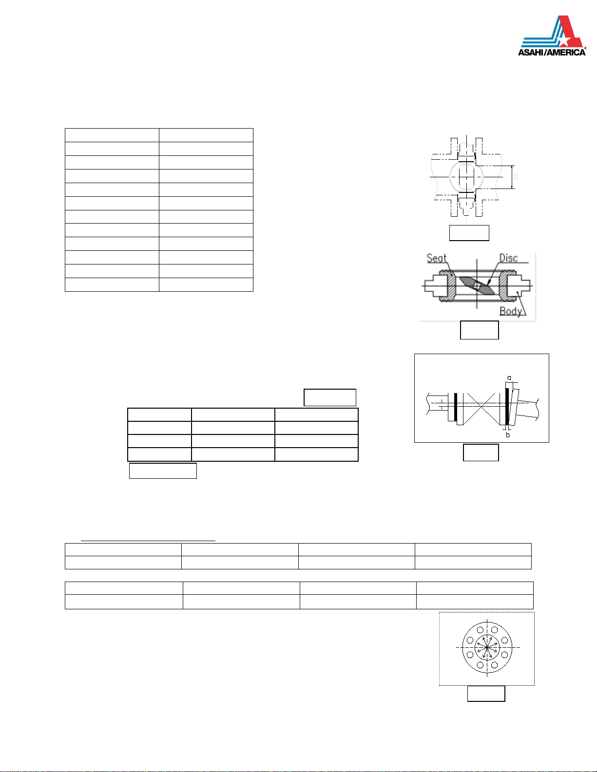
- Lever Type – The direction of the handle is the same as the disc
For full Closed position, the handle is perpendicular to the piping
For Full Open position, the lever handle is parallel to the piping system.
- Gear type
For full Closed, the indicator shows Shut.
For full Open, the indicator shows Open.
General operating Instructions
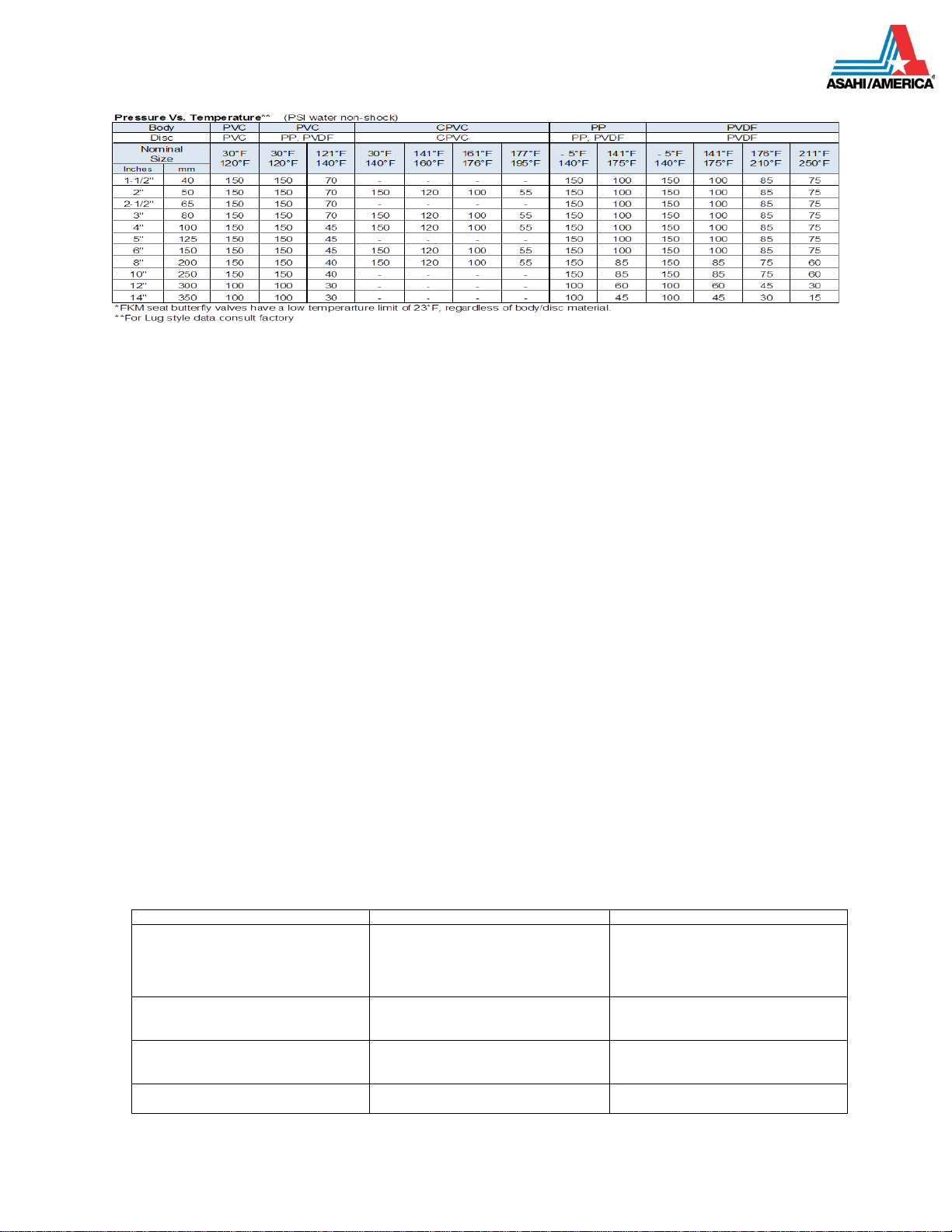
- Operate the valve within the pressure vs. Temperature range as per table below, otherwise the
valve can be damaged
- Select a valve material that is suitable for the media. (Refer to Chemical Resistance on AV Valve)
- Do not step on valve or apply excessive weight (the valve can be damaged)
- Allow sufficient space for maintenance and inspection
- Keep the valve away from excessive heat or fire. (Valve can become deformed or destroyed)
- Make sure to properly dispose of used valves. (Poisonous gas is generated when burned
improperly)
Caution: Do not attempt to repair or replace parts while valve is under pressure.
Refer to Asahi/America Type-57P Operation and Maintenance manual for Disassembly/Assembly or valve
repair.
General Instructions for Transportation, Unpacking and Storage
- Keep the valve packed in original carton box as delivered until installation
- Keep the valve away from any coal, tar, creosote (antiseptic for wood) termite insecticide,
vermicides and paint. (Could cause swelling and damage to the valve)
- Do not impact or drop the valve (It can be damaged)
Visual Maintenance Inspection
1) Check for flaws, cracks, or deformation of the valve.
2) Check for any leaks to the outside of the valve.
3) Check for seat/disc deformation due to improper installation of the valve.
4) Check for smoothness of handle operation.
Troubleshooting
Problem
Cause
Treatment
Fluid leaks in the closed Position
1) Travel stop is not properly set
2) The seat is damaged or worn
3) Foreign materials are trapped
4) the disc is damaged or worn
5) Flange bolt torque uneven/wrong
Adjust the stop
Replace the seat
Remove material
Replace the disc
Adjust and retighten
Fluid leaks to the outside
1) The seat is damaged or worn
2) Flange bolts are not tight or
unevenly torqued
Replace the seat
Properly torque flange bolts
The Handle does not operate
smoothly
1) Foreign materials on disc/seat
2) Gear-op is damaged
3) Flange bolts are overtightened
Remove the materials
Repair and Replace
Adjust and Torque bolts
Valves do not operate
1) The gear-operator is damaged
2) The stem is damaged
Replace Gear operator
Replace the stem
Other Asahi/America Control Unit manuals