manuals.online logo
Brands
  1. Home
  2. •
  3. Brands
  4. •
  5. Asante
  6. •
  7. Chassis
  8. •
  9. Asante AsanteHub 2072RPU User manual

Asante AsanteHub 2072RPU User manual

AsantéHub 2072RPU
Chassis Installation
Guide
• Introducing the Asanté 2072RPU Chassis
on page 3
• Installation on page 6
• Replacing a Power Supply on page 8
• Technical Specifications on page 9
Page 2
AsantéHub 2072RPU Chassis Installation Guide
Technical Support
AsantéTechnologies is committed to providing you with reliable
products and excellent technical support.Please contact us with
any questions,concerns,or suggestions.You can reach us by
phone,letter,or electronic mail,from 6:00AM to 6:00 PM,PST at:
Technical Support
Asanté Technologies, Inc.
821 Fox Lane
San Jose, CA 95131
(800) 622-7464
AppleLink address: ASANTE.TECH
Internet address: [email protected]
Please have the model number prior to contacting technical sup-
port.
Tell us What you Think
There’s always room for improvement andAsantéTechnologies is
always interested in your comments and suggestions about our
product documentation.If you take the time to make suggestions,
we will take the time to read and consider them for new docu-
mentation releases.
Do us a favor and read through this Installation Guide and think
about these questions:
1
What do you like best about this Guide?
2
What do you think is the least valuable or weakest part of
this Guide?
3
What is the most needed improvement you would make to
this Guide?
Think about your answers and then give us a ring.
You can fax your comments and suggestions to:
Asanté Technologies
Attn: Technical Publications
(408) 432-1117
or E-mail us through Internet to:
[email protected]
Page 3
Introducing the Asanté 2072RPU Chassis
Introducing
the Asanté
2072RPU
Chassis
TheAsantéHub 2072RPU (Redundant Power Supply) Chassis is a
dual segment,departmental Ethernet concentrator configured
with two load-sharing power supplies,either of which can assume
the total power budget for the device should one fail.If a failure
occurs in one power supply,the remaining power supply will
automatically take up the additional load.From the viewpoint of
network operations,
there is no delay in switching to a single
power supply
.No packets are dropped and there is no glitch in
network service.
The hub,designed with enterprise-level features,offers a seven-
slot architecture,enabling you to add a variety of multiport
repeater modules with several cabling options,as well as an
SNMP-based network management module (NMM).Some mod-
ules,which fill two slots,provide twice as many ports for connect-
ing to other devices.In complete compliance with the IEEE
specifications for Ethernet,the chassis can be incorporated easily
into an enterprise network orestablish a solid platform for depart-
mental growth.
Figure 1 Asanté 2072RPU Chassis
Power
Off
Green
Red
Stat
= No 
= Norma
= Fail
!
A
SANTE
H
UB
Power
Off
Green
Red
Status
= No AC
= Normal
= Fail
!
Edge of power supply card
Card guide
Page 4
AsantéHub 2072RPU Chassis Installation Guide
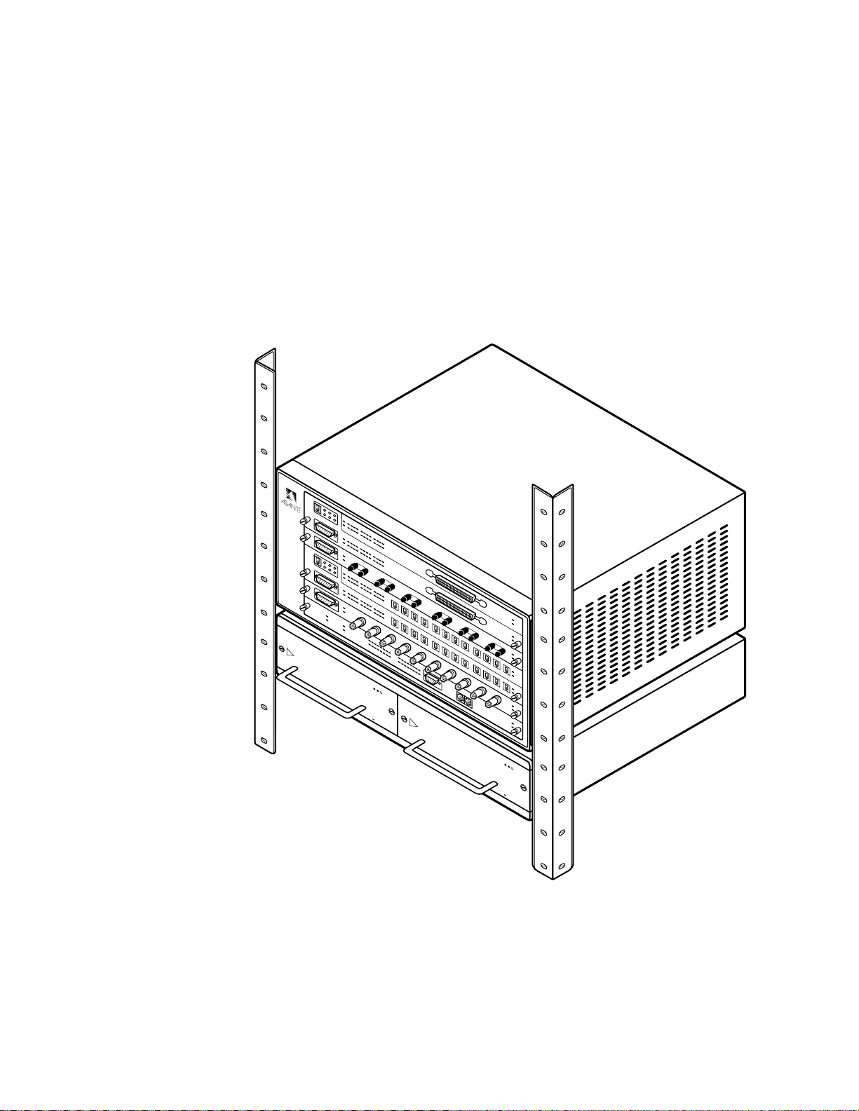
TheAsanté 2072RPU chassis has the following features:
❏
Seven slots to accept a variety of multiport repeater
modules,allowing you to add nodes when needed.
❏
Dual-segment backplane lets you assign any repeater
module in any slot to either of two segments (either Seg-
ment 1 or Segment 2) and create two separate networks
❏
UniversalAC-input switching power supply,thermal pro-
tection scheme and dual-fan architecture
❏
Redundant power supply provides added security in mis-
sion critical applications.
❏
Complete compliance with IEEE 802.3 specifications for
Ethernet
❏
In-band and out-of-band management capabilities using
AsantéView network management software from Macin-
tosh andWindows PC platforms,or from aVT100 termi-
nal
❏
Hot-swappable modules
The 2072RPU chassis accommodates seven slots for single or dou-
ble-slotted multiport repeater modules and a network manage-
ment module.Since all cables attach to the front of the modules,
you can easily access the connections in both rack mount and
desktop installations.
Segment control lets you create separate Ethernet networks using
the chassis’s dual backplane.Using the NMM’s Segment Control
buttons or usingAsantéView software,you can isolate a repeater
module or assign it to one of the two segments.You may choose
to do this to help balance traffic or to separate a module from thje
rest of the network when testing network equipment.
Each of the two power supplies can singularly support the sys-
tem’s full power requirements.This feature is particularly useful
for networks where uptime is extremely critical.
Modules are hot swappable.This means you can make changes or
repairs,without powering down or without interrupting the
whole network.
For detailed information concerning the modules,see the module
installation guides that are shipped with each module.
Page 5
Installation
Installation
This section explains how to install the 2072RPU chassis into a
rack or onto a desk.
TheAsanté 2072RPU chassis package includes the following
items:
❏
Chassis in protective plastic packaging,including two
modular power supplies
❏
TwoAC power cables
❏
Two mounting brackets and ten screws for rack mount-
ing
❏
This installation guide
❏
Warranty card
Required Work Area
Before unpacking the chassis,make sure that you have a large,
dust-free,clean,and electrostatically safe work area.
Positioning the
2072RPU Chassis
To correctly position the chassis,make sure you:
❏
Place the chassis near twoAC outlets,preferably on sepa-
rate circuits
❏
Place the chassis within 100 meters if you are using
twisted pair cable (10BaseT);185 meters for thin Ether-
net cable (10Base2),two kilometers for fiber optic cable
(10BaseF)
❏
Leave a two-inch clearance around the ventilation grills.
❖
Note:Do not place the chassis near sources of electrical
interferences,such as motors or heavy current switches.
❖
Normal office temperature and humidity generally suit this type of
equipment (operating temperature:0
°
to 40
°
C ambient).
Desk Mounting the
Chassis
To desk mount the chassis,do the following steps:
1
Peel the protective strips from the self-adhesive feet and
apply the feet in the four corners of the base of the chassis.
❖
Note:Make sure your desk or table can support approxi-
mately 40 lbs for a fully loaded chassis.
❖
2
Place the chassis on a flat,stable surface.
Page 6
AsantéHub 2072RPU Chassis Installation Guide
Rack Mounting the
Chassis
To rack mount the chassis,do the following steps:
1
Mark the desired location on the rack.
2
Fasten the brackets to the chassis,using the hardware pro-
vided.
3
Fasten the chassis to the rack,(get an assistant to hold it in
place if necessary),using the screws provided.
Figure 2 Rack-Mounting the Chassis
Power
Off
Green
Red
Status
= No AC
= Normal
= Fail
!
Power
Off
Green
Red
Status
= No AC
= Normal
= Fail
!
A
SANTE
H
UB
Page 7
Installation
Powering Up the Hub
This section explains how to power up the hub for functionality.
If you are installing more than one hub,you may want to repeat
this procedure for each hub before attaching any device or net
work connections.
To power up the hub,do the following steps:
1
Make sure the power toggle switch is in the
off
position on
the back panel.
❖
Note:Never remove or insert the power cords with the
power switch turned
on
.
❖
2
Attach the power cords to the sockets on the backpanel
and connect them to anAC outlet.
3
Turn
on
the power switch.
Checking the Fuse
A blown fuse usually indicates a serious problem in the power
supply.Contact technical support to help you determine the
cause and whether you should replace the fuse,or return the orig-
inal for testing and servicing.
To check the fuse,do the following steps:
1
Make sure the power is turned
off
and unplug the hub.
2
Insert a small screwdriver under the fuse faceplate located
on the hub’s front panel and lift if off.
3
Check the fuse to see if it has blown.
A back-up fuse is stored in the fuse holder (small black
box) that is attached to the visible fuse.
❖
Note:Always use the same type of fuse (4A/250V) that
came with the chassis.Failure to do so may result in
damage to the hub.
Page 8
AsantéHub 2072RPU Chassis Installation Guide
Replacing a
Power Supply
TheAsantéHub 2072RPU is powered by two identical power sup-
plies.Replacing either one of the units can be done with power
on the hub.There is no need to shut down the hub and remove it
from network service.To replace a power supply,follow these
simple instructions and refer to the accompanying illustration.
Figure 3 Changing a Power Supply
1
Unscrew the two power supply retaining screws located
on the power supply face plate.
2
Grasp the handle on the front of the power supply and pull
straight out,removing the unit from the chassis.
3
Insert the new unit into the chassis,being careful to align
the edges of the power supply card with the card guide in
the chassis.Push straight in on the handle until the edge
connector at the rear of the power supply seats in its slot.
4
Tighten the two retaining screws.The new unit comes on
line automatically and begins load sharing..
Power
Off
Green
Red
Stat
= No 
= Norma
= Fail
!
A
SANTE
H
UB
Power
Off
Green
Red
Status
= No AC
= Normal
= Fail
!
Edge of power supply card
Card guide
Page 9
Technical Specifications
Technical
Specifications
The technical specifications for theAsanté 2072RPU Chassis are as
follows:
Power Requirements:
InputVoltage:100-240VAC,50-60Hz Single phase;continuous
voltage input range
Input Current: 3A @ 100 VAC (max.)
1.5A @ 220V
5A/250V Fast Blow Fuse
Electromagnetic Emissions:
Meets FCC/VDE ClassA requirement
Safety:
Designed in accordance with UL 1950,CSA 22.2 No.220,IEC
950,TUV andVDE requirements.
Physical Dimensions:
17”W x 10/25”H x 12”L
Weight:
Approximately 25 lbs.(without modules)
Environmental:
OperatingTemperature:0°to 40°C ambient
Operating Humidity:5 to 85% noncondensing
OperatingAltitude:10,000 ft.(3,048m) maximum
StorageTemperature:-30°to 80°C
Storage Humidity:5 to 90% noncondensing
StorageAltitude:25,000 ft.(7,620m) maximum
Warranty:
1 year
Page 10
AsantéHub 2072RPU Chassis Installation Guide
Manual P/N 06-00118-00

Popular Chassis manuals by other brands

THORLABS TXP5016 Operation manual

THORLABS

THORLABS TXP5016 Operation manual

Philips LC8.1E Service manual

Philips

Philips LC8.1E Service manual

National Instruments 9155 user manual

National Instruments

National Instruments 9155 user manual

Racal Instruments 1264C user manual

Racal Instruments

Racal Instruments 1264C user manual

Cisco 6160 Installation and Replacement Notes

Cisco

Cisco 6160 Installation and Replacement Notes

HPE StoreEver MSL4048 instructions

HPE

HPE StoreEver MSL4048 instructions

Lindsay Broadband LB-1000 user manual

Lindsay Broadband

Lindsay Broadband LB-1000 user manual

Chenbro RM245 Series user manual

Chenbro

Chenbro RM245 Series user manual

NXP Semiconductors AFD4400-RDB quick start

NXP Semiconductors

NXP Semiconductors AFD4400-RDB quick start

TP-Link TL-MC1400 user guide

TP-Link

TP-Link TL-MC1400 user guide

Gooxi RMC2108-670-HS user manual

Gooxi

Gooxi RMC2108-670-HS user manual

HPE Apollo 4510 Gen9 Setup and installation guide

HPE

HPE Apollo 4510 Gen9 Setup and installation guide

Anritsu MT1810A installation guide

Anritsu

Anritsu MT1810A installation guide

SilverStone MILO 10 installation guide

SilverStone

SilverStone MILO 10 installation guide

Thinklogical Q-Series product manual

Thinklogical

Thinklogical Q-Series product manual

Advantech HPC-7484 user manual

Advantech

Advantech HPC-7484 user manual

Advantech IPC-3026 user manual

Advantech

Advantech IPC-3026 user manual

ADC Migration Modules DSX-3 installation guide

ADC

ADC Migration Modules DSX-3 installation guide

manuals.online logo
manuals.online logoBrands
  • About & Mission
  • Contact us
  • Privacy Policy
  • Terms and Conditions

Copyright 2025 Manuals.Online. All Rights Reserved.