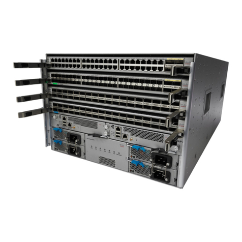
DEV 5072 User manual

User Manual
DEV 5072
Managed Power Supply Chassis
DEV Systemtechnik GmbH
Grüner Weg 4A
61169 Friedberg
GERMANY
Tel: +49 6031 6975 100
Fax: +49 6031 6975 114
support@dev-systemtechnik.com
www.dev-systemtechnik.com
Revision: 2016-11-28
DEV 91-0123-E

User Manual DEV 5072
2 Copyright DEV Systemtechnik GmbH 2016-2017
Table of Contents
1Revision History----------------------------------------------------------- 5
2Introduction---------------------------------------------------------------- 5
2.1 Warranty---------------------------------------------------------------------------------- 5
2.2 Limitation of Warranty---------------------------------------------------------------- 6
2.3 Warnings---------------------------------------------------------------------------------- 6
3Product Description ------------------------------------------------------ 8
3.1 Features and Options------------------------------------------------------------------ 8
3.1.1 Communication Features ------------------------------------------------------------- 8
3.1.2 Power Supply Modules ---------------------------------------------------------------- 8
3.1.3 Other Options---------------------------------------------------------------------------- 9
3.2 Product Drawings--------------------------------------------------------------------- 10
4Installation Instructions------------------------------------------------11
4.1 Scope of Delivery --------------------------------------------------------------------- 11
4.2 Installation of the Product --------------------------------------------------------- 11
4.2.1 Mechanical Assembly of the Product -------------------------------------------- 11
4.2.2 Grounding, Data Cables, and Power Connection ------------------------------ 11
4.2.3 Installation and Exchange of Power Supply Modules ------------------------ 13
4.2.4 Reset of the Device and the Restore of Factory Defaults ------------------- 14
4.3 Device Factory Settings ------------------------------------------------------------- 15
4.3.1 Factory Settings for the DEV 5072 Chassis-------------------------------------- 15
4.3.2 Factory Network Settings ----------------------------------------------------------- 16
4.3.3 Factory SNMP Settings--------------------------------------------------------------- 16
4.4 Communication Interface Configuration --------------------------------------- 17
4.4.1 Serial Interface------------------------------------------------------------------------- 17
4.4.2 Ethernet Interface -------------------------------------------------------------------- 17
4.4.2.1 Ethernet Connection----------------------------------------------------------------------------17
4.4.2.2 Network Setup via the Serial Interface-----------------------------------------------------18
4.4.2.2.1 Start and Termination of the Configuration Program ----------------------------------------------19
4.4.2.2.2 1 set IP address -----------------------------------------------------------------------------------------------20
4.4.2.2.3 2 set netmask -------------------------------------------------------------------------------------------------20
4.4.2.2.4 3 set gateway--------------------------------------------------------------------------------------------------20
4.5 Maintenance Of the Product ------------------------------------------------------ 20
5Operation of the Product ----------------------------------------------21
5.1 Modes of Operation ----------------------------------------------------------------- 21
5.1.1 Local Mode ----------------------------------------------------------------------------- 21
5.1.2 Remote Mode ------------------------------------------------------------------------- 21
5.2 Initialization of the Device --------------------------------------------------------- 21
5.3 Operation at the Device ------------------------------------------------------------ 21

User Manual DEV 5072
Copyright DEV Systemtechnik GmbH 2016-2017 3
5.4 Operation via Web Interface ------------------------------------------------------ 22
5.4.1 Start of the Web Interface---------------------------------------------------------- 22
5.4.2 The Main Window and Common Features of the Main Tabs--------------- 24
5.4.3 Status Tab------------------------------------------------------------------------------- 25
5.4.3.1 Status Tab with UPS-----------------------------------------------------------------------------26
5.4.4 Control Tab ----------------------------------------------------------------------------- 27
5.4.4.1 Power Supply Module--------------------------------------------------------------------------28
5.4.4.2 Control Tab with UPS ---------------------------------------------------------------------------29
5.4.5 Events Tab ------------------------------------------------------------------------------ 33
5.4.6 Setup Tab ------------------------------------------------------------------------------- 35
5.4.6.1 User Setup-----------------------------------------------------------------------------------------36
5.4.6.1.1 Authorization--------------------------------------------------------------------------------------------------36
5.4.6.1.2 Password and Language------------------------------------------------------------------------------------39
5.4.6.1.3 User Management -------------------------------------------------------------------------------------------39
5.4.6.2 System Setup -------------------------------------------------------------------------------------41
5.4.6.2.1 Network---------------------------------------------------------------------------------------------------------41
5.4.6.2.2 SNMP ------------------------------------------------------------------------------------------------------------42
5.4.6.2.3 HTTPS/FTPS ----------------------------------------------------------------------------------------------------43
5.4.6.3 Feature Setup-------------------------------------------------------------------------------------44
5.4.6.3.1 Power Supply Settings --------------------------------------------------------------------------------------44
5.4.6.4 Software Service ---------------------------------------------------------------------------------45
5.4.6.4.1 Restore Factory Defaults -----------------------------------------------------------------------------------45
5.4.6.4.2 Firmware Update---------------------------------------------------------------------------------------------46
5.4.7 Info Tab---------------------------------------------------------------------------------- 47
5.5 Control via Remote Interface: SNMP-------------------------------------------- 48
5.5.1 SNMP Overview ----------------------------------------------------------------------- 48
5.5.2 Private Enterprise Number, Device Index Number --------------------------- 48
5.5.3 The dev-5071 MIB Tree-------------------------------------------------------------- 49
5.5.4 MIB Objects ---------------------------------------------------------------------------- 49
5.5.4.1 .devPowerTraps----------------------------------------------------------------------------------50
5.5.4.1.1 .devPowerTraps.trapAlarmText --------------------------------------------------------------------------50
5.5.4.1.2 .devPowerTraps.trapAlarm--------------------------------------------------------------------------------50
5.5.4.1.3 .devPowerTraps.trapModeChange ----------------------------------------------------------------------50
5.5.4.2 .instrument----------------------------------------------------------------------------------------51
5.5.4.2.1 .instrument.controllerMac --------------------------------------------------------------------------------51
5.5.4.2.2 .instrument.firmwareRevision ----------------------------------------------------------------------------51
5.5.4.2.3 .instrument.instrumentType ------------------------------------------------------------------------------51
5.5.4.2.4 .instrument.mibRevision -----------------------------------------------------------------------------------51
5.5.4.3 .application----------------------------------------------------------------------------------------52
5.5.4.3.1 .application.controlMode----------------------------------------------------------------------------------53
5.5.4.3.2 .application.outputVoltage --------------------------------------------------------------------------------53
5.5.4.3.3 .application.outputCurrent --------------------------------------------------------------------------------53
5.5.4.3.4 .application.numberOfChannels -------------------------------------------------------------------------53
5.5.4.3.5 .application.channelTable ---------------------------------------------------------------------------------53
5.5.4.3.5.1 .application.channelTable.channelEntry.channelIndex--------------------------------------------53
5.5.4.3.5.2 .application.channelTable.channelEntry.channelOn -----------------------------------------------54
5.5.4.3.5.3 .application.channelTable.channelEntry.channelAcInputStatus --------------------------------54
5.5.4.3.5.4 .application.channelTable.channelEntry.channelTempWarning --------------------------------54
5.5.4.3.5.5 .application.channelTable.channelEntry.channelFanStatus --------------------------------------54
5.5.4.3.5.6 .application.channelTable.channelEntry.channelOutVoltageSet--------------------------------55

User Manual DEV 5072
4 Copyright DEV Systemtechnik GmbH 2016-2017
5.5.4.3.5.7 .application.channelTable.channelEntry.channelOutVoltage ------------------------------------55
5.5.4.3.5.8 .application.channelTable.channelEntry.channelOutCurrentSet--------------------------------55
5.5.4.3.5.9 .application.channelTable.channelEntry.channelOutCurrent------------------------------------55
5.5.4.3.5.10 .application.channelTable.channelEntry.channelModuleStatus --------------------------------56
5.5.4.3.5.11 .application.channelTable.channelEntry.channelEnable ------------------------------------------56
5.5.4.3.6 .application.outputVoltageSet----------------------------------------------------------------------------56
5.5.4.3.7 .application.outputCurrentLim ---------------------------------------------------------------------------56
5.5.4.3.8 .application.upsAvailable ----------------------------------------------------------------------------------57
5.5.4.3.9 .application.upsStatus --------------------------------------------------------------------------------------57
5.5.4.3.10 .application.upsLoadVoltage------------------------------------------------------------------------------57
5.5.4.3.11 .application.upsBatteryVoltage --------------------------------------------------------------------------57
5.5.4.3.12 .application.upsBatteryChargeCurrent -----------------------------------------------------------------57
5.5.4.3.13 .application.upsBatteryTemperature -------------------------------------------------------------------58
5.5.4.3.14 .application.upsBatteryTest -------------------------------------------------------------------------------58
5.5.4.4 .surveillance---------------------------------------------------------------------------------------58
5.5.4.4.1 .surveillance.trapEnableMask-----------------------------------------------------------------------------59
5.5.4.4.2 .surveillance.errorEnableMask ---------------------------------------------------------------------------59
5.5.4.4.3 .surveillance.numberOfErrors ----------------------------------------------------------------------------60
5.5.4.4.4 .surveillance.errorTable ------------------------------------------------------------------------------------60
5.5.4.4.4.1 .surveillance.errorTable.errorEntry.errorIndex ------------------------------------------------------60
5.5.4.4.4.2 .surveillance.errorTable.errorEntry.errorNr ----------------------------------------------------------60
5.5.4.4.4.3 .surveillance.errorTable.errorEntry.errorCount------------------------------------------------------60
5.5.4.4.4.4 .surveillance.errorTable.errorEntry.errorDateTime-------------------------------------------------60
5.5.4.4.4.5 .surveillance.errorTable.errorEntry.errorPending---------------------------------------------------61
5.5.4.4.4.6 .surveillance.errorTable.errorEntry.errorAcknowledge--------------------------------------------61
5.5.4.4.4.7 .surveillance.errorTable.errorEntry.errorChassisNumber-----------------------------------------61
5.5.4.4.5 .surveillance.errorDescription ----------------------------------------------------------------------------61
5.6 FTP/FTPS-Server ---------------------------------------------------------------------- 61
6Error Indication-----------------------------------------------------------63
6.1 Software Error Indication ---------------------------------------------------------- 63
6.1.1 Power Errors --------------------------------------------------------------------------- 63
6.1.2 UPS Errors ------------------------------------------------------------------------------ 64
6.1.3 Fan Errors ------------------------------------------------------------------------------- 64
6.1.4 Other Errors ---------------------------------------------------------------------------- 64
7Connectors ----------------------------------------------------------------65
8Technical Data and Options -------------------------------------------65
9Spare Parts ----------------------------------------------------------------65
10 Conformance Declarations --------------------------------------------66
10.1 Certificate of Conformance -------------------------------------------------------- 66
10.2 EU Declaration of Conformity ----------------------------------------------------- 69
11 Glossary --------------------------------------------------------------------70
12 Notes------------------------------------------------------------------------71

User Manual DEV 5072
Copyright DEV Systemtechnik GmbH 2016-2017 5
1Revision History
Revision (Date)
Author
Short Description
A (15-Mar-2016)
WP
First version
B (16-Mar-2016)
MH
Minor corrections
C (16-Jun-2016)
WP
Supplementation of SNMP chapter
D (05-Oct-2016)
WP
Inclusion of UPS functionality
E (28-Nov-2017)
WP
Reworked document format
2Introduction
Thank you for purchasing a DEV 5072 Managed Power Supply Chassis.
This user manual is intended to familiarize you with the installation and operation
of the DEV 5072.
For 48 V applications, this product equipped with 48 V power supply modules can
be combined with the DEV 5101 Online UPS for DEV 5072. As far as this has impact
on the operation of the DEV 5072 this is explained within this documentation, for
all other issues directly related to the DEV 5101 product, please refer to the
corresponding user manual.
The DEV 5072 chassis for professional use can be equipped with one to four power
supply modules, thus realizing a reliable, powerful, and usually redundant source
for DC loads. Naturally, redundancy is provided only if the DEV 5072 is equipped
with more than one power supply module.
DEV Systemtechnik GmbH declares that this equipment meets all relevant
standards and rules. The unit carries a CE mark.
Please read all instructions before installation or usage of the product!
2.1 Warranty
The product has a warranty against defects in material and workmanship for a
period of two years from the date of shipment.
During the warranty period DEV Systemtechnik will, at its option, either repair or
replace the product if it turns out to be defective.
For warranty, service, or repair, the product must be returned to DEV System-
technik. The customer has to pay shipping charges to DEV Systemtechnik and
DEV Systemtechnik will pay shipping charges to return the product to the customer.
However, the customer is obliged to pay all duties, all taxes, and all other additional
costs arising from the shipment of the product.
DEV Systemtechnik warrants that the software and firmware designated by
DEV Systemtechnik for use with the product will execute its programming
instructions if installed properly. DEV Systemtechnik does not warrant that the
operation of the product, software, or firmware will be uninterrupted or error-free.

User Manual DEV 5072
6 Copyright DEV Systemtechnik GmbH 2016-2017
2.2 Limitation of Warranty
The preceding warranty does not apply to defects resulting from:
improper site preparation or site maintenance
improper or inadequate interfacing of the product
unauthorized modification or misuse of the product
the application of software supplied by the customer
improper or inadequate maintenance of the product
operation beyond the environmental conditions specified for the product
2.3 Warnings
The warnings in this chapter apply to the DEV 5072 Managed Power Supply
Chassis.
In combination with the DEV 5101 Online UPS for DEV 5072 there are additional
warnings stated in the DEV 5101 user manual!
The following safety measures must be observed during all phases of operation,
service, and repair of this equipment. Failure to comply with the safety precautions
or warnings in this document violates safety standards of design, manufacturing,
and intended use of this equipment and may affect the built-in protections.
DEV Systemtechnik shall not be liable for the failure of users to comply with these
requirements.
Disconnect the device from any external power line before opening of the housing.
In any case, the device is to be opened by trained service staff, only.
Environmental Conditions
The equipment is designed for indoor use and for an ambient temperature range of
-10…+50 °C (14…122 °F) at 100 % load. The maximum operational altitude is
3000 m (3280 yds.) above sea level.
Mechanical Integration
It is not permitted to fix the chassis on the rack mount flanges, only.
Balanced weight distribution of the chassis has to be ensured by placing it on a solid
surface or by using rack rails.
Sufficient airflow through the DEV 5072 must be ensured to achieve best cooling
results. Do not block or obstruct the airflow through the chassis at the front and at
the rear side, e.g. by placing large components close to the front side.
It is recommended to provide 1 RU space in the rack above and below the chassis
to ensure a good air circulation.
Heat Hazard
Top, bottom, and side surfaces may become hot when operating the unit
continuously. To reduce the risk of injury from a hot surface, allow the surface
(particularly of a power supply module) to cool before touching.
Grounding, AC Connection, Cables
To minimize shock hazard the chassis must be connected to an electrical ground via
a ground wire, please refer to chapter 4.2.2. For the AC power connection, the
device must be connected to the AC power supply mains through a power cable
with three conductors per each installed power supply module and with the ground
wire firmly connected to an electrical ground (safety ground) at the power outlet.

User Manual DEV 5072
Copyright DEV Systemtechnik GmbH 2016-2017 7
Any interruption of the protective ground conductor will cause a potential shock
hazard that might cause personal injury.
Risk of electrical shock and energy hazard:
Disconnecting one power supply line disconnects only one power supply module.
To isolate the DEV 5072 completely, disconnect all power supply lines!
Do not connect the DEV 5072 to mains supply exceeding the specifications for input
voltage (100…240 V AC ±10 %) and frequency (50…60 Hz).
The recommended AC cables to be applied are standard high temperature power
cables with type IEC 60320-C19 appliance plug appropriately rated to the
conditions of the country where the DEV 5072 is operated (e.g. European Union:
16 A/250 V; USA/Canada: 20 A/250 V).
For the characteristics of the DC output connections to be applied refer to the
related notes of chapter 4.2.2.
Live Circuits
Operating staff must not remove the cover of the DEV 5072 chassis or the cover of
power supply modules!
No component replacement is allowed for service staff that is not trained by
DEV Systemtechnik. To avoid injuries trained service staff has always to disconnect
all power connections, to discharge circuits, and to remove external voltage
sources before touching or replacing components.
Energy Hazard
The output terminals of the DEV 5072 chassis and the connector at the rear side of
power supply modules are capable of providing hazardous energy.
Due to the hazardous energy level, the output terminals and the power supply
module connectors therefore must not be accessible to operating staff.
For trained service staff protection has to be provided against inadvertent contact
with the output terminals of the DEV 5072 chassis.
Overcurrent Protection
A readily accessible branch circuit over current protective device (rated 30 A max.)
per each power supply line must be incorporated in the building wiring.
Each protective device must disconnect both poles of the power supply line
simultaneously.
Fuse
The internal fuse of a power supply module is sized for fault protection. If a fuse
was opened this indicates that service is required. Fuse replacement is to be
performed by trained service staff, only. The rating of the internal power supply
module fuse is F25 A H 250 V AC.

User Manual DEV 5072
8 Copyright DEV Systemtechnik GmbH 2016-2017
3Product Description
DEV Systemtechnik has developed with the DEV 5072 a compact 1 RU chassis that
can be populated with one to four power supply modules. Each of the power
supply modules is capable to deliver up to 2500 W. Thus, the product provides up
to 10000 W at the two sets of robust galvanically isolated DC output terminals if
equipped with four power supply modules.
3.1 Features and Options
3.1.1 Communication Features
In addition to the LEDs at the power supply modules (please refer to chapter 3.1.2)
and to the "Status" LED at the rear side of the chassis (chapter 5.3), the DEV 5072
provides a Web Interface and SNMP support for the control and for the surveillance
of the product:
The Web Interface (chapter 5.4) is intended to serve as the local user interface for
operating the DEV 5072. It provides features for checking the health status and for
changing the setup and specific parameters of the device.
The implementation of SNMP (Simple Network Management Protocol) via the
Ethernet interface permits remote monitoring and control of the device
(chapter 5.5).
Finally, the device provides an FTP/FTPS-server for downloading log files and for
uploading firmware updates (chapter 5.6).
3.1.2 Power Supply Modules
As stated above, the DEV 5072 chassis can be equipped with up to four power
supply modules to deliver the required power. It is recommended to install an
additional power supply module for the pursued power in order to provide
redundancy if one of the power supply modules fails.
The three available types of power supply modules are to be ordered separately.
The types are different with respect to their DC output voltage: 12 V, 24 V, or 48 V.
Please refer to chapter 9 for the (spare) part numbers.
The LEDs at each power supply module are signalizing the operating status:
DCAC
HFE2500-12/S
The "AC" LED signalizes that the power supply module is supplied with primary
power which is within specifications (green) or not (red).
The "DC" LED signalizes that the output voltage delivered by the power supply
module is within specifications (green) or not (red). Additionally, the LED is red
if the power supply module is deactivated via Web Interface (chapter 5.4.4.1)
or via SNMP (chapter 5.5.4.3.5.2); if the applied power supply module is not
approved by DEV Systemtechnik; and if the power supply module type does not
match the output voltage configuration of the DEV 5072 chassis (please refer to
the note below).

User Manual DEV 5072
Copyright DEV Systemtechnik GmbH 2016-2017 9
The extraction handle surrounding the module front in combination with the
module lock on the lower left side permits the convenient exchange of a module
(chapter 4.2.3). Power supply modules can be removed, installed, and/or
exchanged even during the operation of the device.
Note:
The DEV 5072 chassis is to be populated with one to four power supply
modules providing the same DC output voltage.
The installation of power supply modules usually starts in slot 1 (most left slot
at the front side of the chassis); unused slots are covered with a blind plate if
less than four power supply modules are installed.
The output voltage configuration of the DEV 5072 chassis is determined by the
power supply module located (and successfully detected) in slot 1 during the
latest power-up. The output voltage of all other installed power supply
modules has to match the output voltage of this power supply module.
I.e. it has to be made sure that all power supply modules in all slots of the DEV
5072 chassis are of the same type.
Please consider that if slot 1 is not populated during power-up, the output
voltage configuration of the DEV 5072 chassis remains unchanged.
AC plugs at the rear side of the chassis are not to be connected if the
corresponding power supply module slot is not populated!
If one of the power supply modules is deactivated via Web Interface
(chapter 5.4.4.1) or via SNMP (chapter 5.5.4.3.5.2), the "DC" LED of this power
supply module is red indicating that it is not delivering output voltage.
If all power supply modules are deactivated via Web Interface or via SNMP (i.e.
no power supply module delivers output voltage, but the AC connections are
established), the "AC" LED of all installed power supply modules is on.
The following table informs about the maximum ratings for each type of power
supply module, chapter 4.2.2 states the ratings of the chassis. Note that the
maximum output current is reduced by 5 % if more than one power supply
module is installed in the chassis.
Output
Output Voltage
265 > Vin > 170 V AC
170 > Vin > 100 V AC
Voltage
Adjust Range
Current
Power
Current
Power
12 V
9.6…13.2 V
≤200 A
≤2400 W
≤125 A
≤1500 W
24 V
19.2…29.0 V
≤104 A
≤2496 W
≤62.5 A
≤1500 W
48 V
38.4…58.0 V
≤52 A
≤2496 W
≤31.25 A
≤1500 W
3.1.3 Other Options
Eight Web Interface licenses are included in the delivery of the DEV 5072; addi-
tional licenses for the Web Interface can be ordered initially via Option 79. It is
possible to purchase additional license keys at any time, please contact
DEV Systemtechnik.

User Manual DEV 5072
10 Copyright DEV Systemtechnik GmbH 2016-2017
3.2 Product Drawings
The rear side of the DEV 5072 is identical for all product configurations.
For the appearance of the front side of the DEV 5072, it has mainly to be distin-
guished which type and number of power supply modules is installed.
Thus, only a single drawing of the front side is provided, other configurations can
be easily derived from that.
For a product view in combination with the DEV 5101 Online UPS for DEV 5072,
please refer to the DEV 5101 user manual.
Front View:
DCAC
HFE 2500 -48/S
DCAC
HFE 2500 -48/S
DCAC
HFE 2500 -48/S
PS2PS1PS3PS4
PS1
Slot for power supply module 1 equipped with a 48 V power supply module
PS2
Slot for power supply module 2 equipped with a 48 V power supply module
PS3
Slot for power supply module 3 equipped with a 48 V power supply module
PS4
Slot for power supply module 4 covered with a blind plate
Rear View:
Reset
Status
AC3AC2AC1AC4GND -A+A
Com
Eth-B+BStatus
Reset
+B, -B
Secondary DC output terminals
AC4
AC plug for power supply module slot 4
Reset
"Reset" push button
Status
"Status" LED
Eth
Ethernet connector, RJ-45
Com
Serial interface connector, Sub-D 9 (f)
AC3
AC plug for power supply module slot 3
AC2
AC plug for power supply module slot 2
GND
Grounding bolt
AC1
AC plug for power supply module slot 1
-A, +A
Primary DC output terminals

User Manual DEV 5072
Copyright DEV Systemtechnik GmbH 2016-2017 11
4Installation Instructions
4.1 Scope of Delivery
1 * DEV 5072 Managed Power Supply Chassis
equipped with the type and number of power supply modules as ordered
1 * User manual (this document)
4.2 Installation of the Product
4.2.1 Mechanical Assembly of the Product
Please refer to the warnings in chapter 2.3 regarding the mechanical integration of
the DEV 5072. For the assembly in a 19" rack the rack slots must be prepared with
rails for the chassis. After inserting the chassis in the rack, fix the chassis with four
screws to the rack at its rack mount flanges.
For the assembly in combination with the DEV 5101 Online UPS for DEV 5072,
please refer to the DEV 5101 user manual.
4.2.2 Grounding, Data Cables, and Power Connection
Reset
Status
AC3AC2AC1AC4GND -A+A
Com
Eth-B+BStatus
Reset
+B
Secondary DC output terminal for positive polarity
-B
Secondary DC output terminal for negative polarity
AC4
AC plug for power supply module slot 4
Reset
"Reset" push button
Status
"Status" LED
Eth
Ethernet connector, RJ-45
Com
Serial interface connector, Sub-D 9 (f)
AC3
AC plug for power supply module slot 3
AC2
AC plug for power supply module slot 2
GND
Grounding bolt
AC1
AC plug for power supply module slot 1
-A
Primary DC output terminal for negative polarity
+A
Primary DC output terminal for positive polarity
For the warnings for the DEV 5072 with respect to "Grounding, AC Connection,
Cables" please refer to chapter 2.3.
First, the DEV 5072 chassis needs to be connected to the rack via a ground wire.
The grounding bolt (labeled GND in the figure above) is located on the right at the
rear side of the chassis between the AC plugs for the second (AC2) and for the first
(AC1) power supply module slot. To connect a cable, please take off the upper nut
and the first washer of the grounding bolt. Then connect the grounding cable which
must have a ring tongue terminal matching the M4 fastening bolt. The washer and
the nut have to be tightened again.
Next, establish the external Ethernet connection by plugging the appropriate
Ethernet cable from your network to the Ethernet port of the device (Eth); the
configuration of the Ethernet interface is described in chapter 4.4.2.
In combination with the DEV 5101, the serial interface of the DEV 5072 is to be
connected to the Battery Management Controller (BMC) chassis as stated in the
DEV 5101 user manual. For standalone applications of the DEV 5072 and if the basic

User Manual DEV 5072
12 Copyright DEV Systemtechnik GmbH 2016-2017
network setup via serial interface is required (chapter 4.4.2.2), a serial connection
between a PC and the serial connector (Com) of the DEV 5072 is to be established
using a 1:1 cable; the configuration is described in chapter 4.4.1.
Please refer to the corresponding chapters for the functionality of the push button
(Reset, chapter 4.2.4) and of the LED (Status, chapter 5.3).
Before connecting AC power cables the DC output connections (to be realized
either as cables or as solid connection bars) are to be installed. Due to the high
output current of the DEV 5072 chassis, both sets of the DC output terminals
(+A/-A, +B/-B) are to be used for the DC wiring. Note that the maximum rating per
set of the DC output terminals is 380 A and that it is highly recommended that the
output load is distributed evenly among both DC output terminal sets!
The prepared DC output connections are to be attached using the provided
M6 nuts. It has to be ensured that the M6 nuts at the power supply chassis for
securing the DC output connections are tightened with a torque of 4.1…7.3 Nm
(36.3…64.6 lbf-in).
Note:
In combination with the DEV 5101, the instructions for the DC wiring are
different; please refer to the DEV 5101 user manual.
If using cables for the DC output connections, the number and the diameters of
the cables depend on the current to be supplied and on the length of the
cables. Make sure that an appropriate configuration with respect to number
and to diameter of the cables is installed.
For the cable cross section per polarity and per set of output terminals with an
assumed total maximum output current of 200 A, a minimum of 35 mm² cable
cross section is according to regulations.
The next table informs regarding the total maximum output current of the
chassis (i.e. assumed input voltage >170 V AC) with respect to the installed type
and number of power supply modules:
# Power Supplies
Voltage
1
2
3
4
12 V
200 A
380 A
570 A
760 A
24 V
104 A
198 A
297 A
395 A
48 V
52 A
98 A
147 A
196 A
For the connection of cables to the M6 threaded studs of the DC output
terminals double-hole lugs with 15 mm (~5/8") center distance and 90° cable
taps capable of at least AWG 2 (i.e. ~35 mm²) wires are recommended, e.g.
Burndy YA2CL2TC1490. As an alternative, a number of ring tongue terminals
with an inner diameter of 6 mm (0.24") and with a maximum outer diameter of
14 mm (0.55") can be used.
The DEV 5072 can be used to supply a positive DC voltage by connecting the
DC output connections in the fashion that the positive connections are running
to the positive DC output terminals (+A, +B). The negative DC output
connections are to be attached to the negative DC output terminals (-A, -B).
To obtain a negative DC voltage the polarity of the DC output connections has
to be reversed, i.e. the negative DC output connections are to be attached to
the positive DC output terminals (+A, +B) and the positive DC output
connections are running to the negative DC output terminals (-A, -B).

User Manual DEV 5072
Copyright DEV Systemtechnik GmbH 2016-2017 13
The grounding bolt is independent of the potential of the output terminals and
is connected to PE (Protective Earth) potential of the AC plugs as well as to the
ground (GND) potential of the data interface connectors.
Next, after the application of the DC output wiring, connect appropriate AC power
cables (chapter 2.3) to the AC plugs (AC1…AC4, IEC 60320-C20). Depending on the
number and on the location of the installed power supply modules, only the
corresponding AC power cables are to be connected.
Finally, make sure that all installed power supply modules of the DEV 5072 are
powered up sequentially (to minimize the switch-on surge) without the connected
load being turned on! If the power supply modules are powered up sequentially
with the connected load turned on, there is the risk of overloading already
activated power supply modules before the necessary number of activated power
supply modules is delivering the required power.
Note:
Due to the high power consumption of each power supply module, it is highly
recommended to use separately fused phases of the available AC mains.
The installation location of the power supply modules can be selected freely,
though it is recommended to install the power supply modules in the slot order
(as shown in the front view figure of chapter 3.2).
Make sure that the corresponding AC power cables are connected.
4.2.3 Installation and Exchange of Power Supply Modules
The DEV 5072 is delivered with the number of ordered power supply modules that
are already installed. Therefore, you may proceed in reading the next chapter.
In case that a power supply module has to be exchanged or that a DEV 5072 is to
be upgraded with an additional power supply module, the following instructions
are to be noticed. Please consider the related warnings stated in chapter 2.3.
Though the power supply modules are hot pluggable, it is recommended for
exchange operations either to power down the DEV 5072 or at least to deactivate
the corresponding power supply module via Web Interface (chapter 5.4.4.1) or via
SNMP (chapter 5.5.4.3.5.2).
DCAC
HFE 2500 -4 8/S
DCAC
HFE 2500 -4 8/S
DCAC
HFE 2500 -4 8/S
To install an additional power supply module remove the blind plate covering the
desired slot in the first step.
To remove -for instance- the first power supply module from the chassis, elevate
the module lock (indicated by the vertical green arrow in the figure above) and pull
the extraction handle (horizontal red arrows in the figure above) simultaneously.
Please check type and output voltage of the spare (or additional) power supply
module before the installation, since it has to be made sure that all power supply
modules in all slots are of the same type (please refer to the note in chapter 3.1.2
regarding the output voltage configuration of the DEV 5072 chassis).
Install the (replacement) power supply module by gently pushing it into the chassis
with the extraction handle closed. Lift the module lock during the last section of the
insertion process and make sure that the module is inserted deep enough (the

User Manual DEV 5072
14 Copyright DEV Systemtechnik GmbH 2016-2017
front of the module has to level with the chassis frame) and that the lock becomes
engaged when releasing it.
Next -and if applicable-, the DEV 5072 can be powered up.
If the DEV 5072 was powered up during a power supply module exchange, the new
power supply module is activated automatically (if type and output voltage are
correct). If there were changes on the default configuration (chapter 4.3.1) of the
corresponding module, the current settings are transferred to the new module.
This can be verified easily by checking the settings via the Web Interface.
If the DEV 5072 is upgraded with an additional power supply module, the
surveillance of the power supply is to be enabled via the Web Interface
(chapter 5.4.4.1) or via SNMP (chapter 5.5.4.3.5.11).
4.2.4 Reset of the Device and the Restore of Factory Defaults
During power-up or after a reset of the device, the controller of the DEV 5072
performs a health check and scans the assemblies of the device e.g. to detect,
whether a module is installed in a slot or not. If there is a module installed, the
settings for this slot are transferred to the module.
A reset of the DEV 5072 is necessary only if there were applied elementary
changes, e.g. restoring the factory defaults via Web Interface.
The reset of the device can be performed in three different ways:
1. Reset via the "Reset" push button located at the rear side of the chassis
(please refer to the drawing in chapter 4.2.2): Press and hold (e.g. by using a
ballpoint pen) the "Reset" button for approximately 3 seconds.
2. Reset via the serial interface when terminating the configuration program
(chapter 4.4.2.2.1).
3. Reset via Web Interface (chapter 5.4.6.4.2).
Note:
During a reset, the device still delivers output voltage, i.e. the power supply
module outputs are not deactivated while resetting the device.
If a power supply module was deactivated via Web Interface (chapter 5.4.4.1)
or via SNMP (chapter 5.5.4.3.5.2), it will be activated after a power cycle or
after a reset!
It takes about 60 seconds after a reset or after a power cycle that the device is
completely accessible again via the serial interface, via Web Interface, and via
SNMP.
If –for any reason–a restore of the factory defaults is required, please proceed
as described in the following:
Usually, the factory settings (chapter 4.3) can be restored via Web Interface (chap-
ter 5.4.6.4.1). If –for any reason–the device is not accessible via Web Interface, the
factory settings can be restored in the following manner:
Press and hold the "Reset" push button located at the rear side of the chassis
(e.g. by using a ballpoint pen).
After ~20…50 seconds the yellow LED on the "Ethernet" connector starts to blink
(8 times, for ~4 seconds). If the "Reset" push button is released during this
blinking, the factory settings are restored and a device reset is initiated.

User Manual DEV 5072
Copyright DEV Systemtechnik GmbH 2016-2017 15
4.3 Device Factory Settings
The DEV 5072 is delivered with factory settings as described in the following.
It is possible to restore these settings, please refer to chapter 4.2.4.
4.3.1 Factory Settings for the DEV 5072 Chassis
The factory settings for the DEV 5072 are dependent on the configured power
supply module type:
1. DEV 5072 configured for 12 V Power Supply Modules
Voltage Setpoint / Current Alarm Level: 12.0 V / 684.0 A
2. DEV 5072 configured for 24 V Power Supply Modules
Voltage Setpoint / Current Alarm Level: 24.0 V / 355.6 A
3. DEV 5072 configured for 48 V Power Supply Modules
Voltage Setpoint / Current Alarm Level: 48.0 V / 177.8 A
In combination with the DEV 5101, the output voltage it is determined by the
battery voltage and cannot be adjusted!
Otherwise, the output voltage setpoint for the DEV 5072 chassis can be adjusted in
a range as described in chapter 3.1.2 via Web Interface (please refer to chapter
5.4.4) and via SNMP (chapter 5.5.4.3.6).
The current alarm level for the DEV 5072 chassis can be changed via Web Interface
(chapter 5.4.4) and via SNMP (chapter 5.5.4.3.7). If the total current of the chassis
exceeds the current alarm level, this is just used for warning notice purposes and
does not physically limit the output current.
The other limitations for the power supply modules which need to be considered
depend on the AC input voltage: As shown in in chapter 3.1.2 a power supply
module delivers up to 1500 W power if supplied with 100…170 V AC and is capable
to deliver more power if the AC input voltage is larger than 170 V AC (but smaller
than 265 V AC).
Note –if not in combination with the DEV 5101–that it is possible to alter the
relation of the output voltage setpoint and of the current alarm level to values that
may exceed the capabilities of the DEV 5072 chassis and of the power supply
modules. Since the firmware does not restrict the input set values according to the
present operating environments, please consider the conditions regarding AC input
voltage, DC output voltage, and the number of installed power supplies. The table
below may assist for altering the factory settings for the current alarm level of the
device (via Web Interface and/or via SNMP).
Note:
For input voltages >170 V AC and if the output voltage is adjusted to values
below the nominal voltage of the applied power supply modules, the maximum
feasible current of the power supply modules (as stated in chapter 3.1.2)
becomes the limiting factor; i.e. the resulting output power is lower as for
higher output voltages. E.g. if a chassis equipped with a single 12 V power
supply module and if the output voltage is adjusted to the lower limit, this
results in 9.6 V * 200 A = 1920 W for the applied power supply module instead
of the 2400 W power for output voltages ≥12 V.
After the exchange of a power supply module, the replacement power supply
module inherits the settings of the corresponding slot.

User Manual DEV 5072
16 Copyright DEV Systemtechnik GmbH 2016-2017
The current measurement accuracy of the power supply modules is 10 %. I.e.
do not be alarmed if a power supply modules displays a current of e.g. 10 A
without a load attached.
The following table provides an overview on the maximum possible output
current for the DEV 5072 considering the AC input voltage range, the output
voltage setpoint, and the type and number of installed power supply modules.
It may be useful for adjusting the current alarm level of the device (via Web
Interface and/or via SNMP). Please note that the default value for the current
alarm level is defined as ~90 % of the absolute maximum possible output
current.
AC Input Voltage Range
(Module Output Power)
Output
Voltage
with
1 module
with
2 modules
with
3 modules
with
4 modules
12 V Power Supplies
Maximum Possible Output Current:
170…265 V AC (2400 W)
9.6 V
200.0 A
380.0 A
570.0 A
760.0 A
170…265 V AC (2400 W)
12.0 V
200.0 A
380.0 A
570.0 A
760.0 A
170…265 V AC (2400 W)
13.2 V
181.8 A
363.6 A
545.5 A
727.3 A
100…170 V AC (1500 W)
9.6 V
156.3 A
312.5 A
468.8 A
625.0 A
100…170 V AC (1500 W)
12.0 V
125.0 A
237.5 A
356.3 A
475.0 A
100…170 V AC (1500 W)
13.2 V
113.6 A
227.3 A
340.9 A
454.5 A
24 V Power Supplies
Maximum Possible Output Current:
170…265 V AC (2496 W)
19.2 V
104.0 A
197.6 A
296.4 A
395.2 A
170…265 V AC (2496 W)
24.0 V
104.0 A
197.6 A
296.4 A
395.2 A
170…265 V AC (2496 W)
29.0 V
86.1 A
172.1 A
258.2 A
344.3 A
100…170 V AC (1500 W)
19.2 V
78.1 A
156.3 A
234.4 A
312.5 A
100…170 V AC (1500 W)
24.0 V
62.5 A
118.8 A
178.1 A
237.5 A
100…170 V AC (1500 W)
29.0 V
51.7 A
103.4 A
155.2 A
206.9 A
48 V Power Supplies
Maximum Possible Output Current:
170…265 V AC (2496 W)
38.4 V
52.0 A
98.8 A
148.2 A
197.6 A
170…265 V AC (2496 W)
48.0 V
52.0 A
98.8 A
148.2 A
197.6 A
170…265 V AC (2496 W)
58.0 V
43.0 A
86.1 A
129.1 A
172.1 A
100…170 V AC (1500 W)
38.4 V
39.1 A
78.1 A
117.2 A
156.3 A
100…170 V AC (1500 W)
48.0 V
31.3 A
59.4 A
89.1 A
118.8 A
100…170 V AC (1500 W)
58.0 V
25.9 A
51.7 A
77.6 A
103.4 A
4.3.2 Factory Network Settings
The factory network settings of the device are:
IP-Address: 192.168.0.11
Netmask: 255.255.255.0
Gateway: 192.168.0.99
For changing the network setup, please refer to chapters 4.4.2.2 & 5.4.6.2.1.
4.3.3 Factory SNMP Settings
The factory SNMP settings are configured as follows:
Read Community: public
Write Community: private
Local/Remote changeable via SNMP:
Additionally, the default community for all four Trap Destination IP Addresses is set
to public and all configurable traps are disabled. If an address is defined without the
explicit port assignment, the standard SNMP trap port 162 is assigned implicitly.
For changing the SNMP setup, please refer to chapter 5.4.6.2.2.

User Manual DEV 5072
Copyright DEV Systemtechnik GmbH 2016-2017 17
There are software factory settings for some SNMP objects, please refer to the
corresponding chapters:
.application.controlMode chapter 5.5.4.3.1
.application.outputVoltageSet chapter 5.5.4.3.6
.application.outputCurrentLim chapter 5.5.4.3.7
.application.channelTable.channelEntry.channelEnable chapter 5.5.4.3.5.11
.surveillance.trapEnableMask chapter 5.5.4.4.1
.surveillance.errorEnableMask chapter 5.5.4.4.2
4.4 Communication Interface Configuration
Two hardware interfaces are provided for the communication with the device:
a serial interface and an Ethernet interface.
In combination with the DEV 5101, the serial interface of the DEV 5072 is used for
the communication with the battery management controller chassis as stated in
the DEV 5101 user manual. For standalone applications of the DEV 5072, the serial
interface can be used for the basic network setup. The Ethernet interface of the
DEV 5072 is used for the operation of the device via Web Interface or via SNMP,
and for the access via the integrated FTP/FTPS-server (chapter 5.6).
4.4.1 Serial Interface
The Sub-D 9 pos female connector for the standard serial RS 232 interface is
located in the middle at the rear side of the DEV 5072 chassis; chapter 7 describes
the pin assignment.
The serial interface configuration for DEV 5072 standalone applications is described
by the following parameters:
Transmission rate: 38400
Data bits: 8
Parity check: none
Start/Stop bit: 1
Handshake: none
In combination with the DEV 5101, the serial interface configuration of the
DEV 5072 is different; please refer to the DEV 5101 user manual.
4.4.2 Ethernet Interface
The RJ-45 connector for the 100Base-TX Ethernet interface is located at the rear
side of the DEV 5072; for the pin assignment please refer to chapter 7.
4.4.2.1 Ethernet Connection
If the device is to be connected to a PC only, the connection can be established via
a direct Ethernet cable (or through a local hub/switch) between the Ethernet
connector of the device and the Ethernet connector of the PC. The network setup
of the PC is to be altered that it is in the same subnet as the device. If it is intended
to use the factory network settings, the IP address of the standalone PC is to be set
to 192.168.0.x, with xin the range 1…254, except 11, which is the default address of the
device, e.g. set the IP address of the standalone PC to the default gateway address
192.168.0.99.

User Manual DEV 5072
18 Copyright DEV Systemtechnik GmbH 2016-2017
If the device is to be connected to the local network, make sure to change the
network setup as required. Ask your network administrator for the details on
network parameters which are to be used.
The factory network settings are subject of chapter 4.3.2.
There are implemented two different methods to change the network setup; either
via Web Interface (please refer to chapter 5.4.6.2.1) or via the serial interface as
described in the following chapter.
4.4.2.2 Network Setup via the Serial Interface
Note that in combination with the DEV 5101 the connection for the network setup
via the serial interface is realized differently; please refer to the DEV 5101 user
manual.
To change a few elementary parameters of the network setup via the serial
interface for a standalone DEV 5072, establish a hardware connection between a
RS 232 port of a PC (e.g. COM1) and the DEV 5072 serial interface using a straight
cable; please refer to chapter 7 for the pin assignment of the serial connector.
Next, start a terminal application (e.g. MS Windows HyperTerminal) on your PC.
Note:
The interface settings of the terminal application have to match the serial
interface configuration (chapter 4.4.1); otherwise, it is not possible to enter the
configuration program as described below.
The terminal application is to be configured that the "Backspace" or "←" key on
the keyboard works properly in the application, and that it sends a <CR> only
(and not a <CR><LF>) when hitting the "Enter" or the "" key on the keyboard.
If using MS Windows HyperTerminal, select the "Properties" entry from the
"File" menu and click on the "Settings" tab. There select "ANSI" from the
"Emulation:" drop down list and then click on the button to
uncheck "Send line ends with line feeds" as shown in the following figure:

User Manual DEV 5072
Copyright DEV Systemtechnik GmbH 2016-2017 19
4.4.2.2.1 Start and Termination of the Configuration Program
In this application the serial interface is exclusively used for the configuration pro-
gram, i.e. if the terminal application is started (and connected) either the following
text is displayed initially or after hitting the "Enter" or "" key on the keyboard:
DEV login:
With the following authentication the configuration program is started:
DEV login: config<CR>
Password: devConfig<CR>
Note:
<CR> stands for hitting the "Enter" or "" key on the keyboard.
All characters/commands to be entered are case sensitive.
After successful authentication, the configuration program is launched. After start
and after the finalization of most of the choices the program lists the choices that
can be performed:
config
======
1 set IP address (192.168.0.225)
2 set netmask (255.255.0.0)
3 set gateway (192.168.0.99)
q quit without saving
x save configuration and exit
your choice >
Choices can be executed by typing the character in the first column of each line
followed by a <CR>. The second column of each line provides a short description of
the choice and the third column displays in parentheses the current setting of the
corresponding choice. In the example above, the IP address and the netmask are
different from the factory network settings (please refer to chapter 4.3.2).
When using the "q" choice the configuration program terminates and the login
message is displayed again:
DEV login:
When using the "x" choice the configuration program saves all changes made and
resets the device (i.e. rebooting the device):
your choice > x<CR>
rebooting the device, please wait...
Again, during a reset the device still delivers output voltage, i.e. the power supply
module outputs are not deactivated while resetting the device.
After a device reset it takes a few moments before the serial interface is accessible
again as described at the beginning of this chapter.
In the following, the available choices are explained:

User Manual DEV 5072
20 Copyright DEV Systemtechnik GmbH 2016-2017
4.4.2.2.2 1 set IP address
This choice is used to change the IP address of the device:
(...)
your choice > 1<CR>
Current IP address is 192.168.0.225
Enter IP address ('NONE' to clear) >
To change the current IP address type in a different valid address; to clear the
address type in "NONE<CR>"; and just entering <CR> maintains the current setting:
Enter IP address ('NONE' to clear) ><CR>
unchanged
4.4.2.2.3 2 set netmask
This choice is used to change the netmask of the device:
(...)
your choice > 2<CR>
Current netmask is 255.255.0.0
Enter netmask ('NONE' to clear) >
To change the current netmask type in a different valid entry; to clear it type in
"NONE<CR>"; and just entering <CR> maintains the current setting.
4.4.2.2.4 3 set gateway
This choice is used to change the gateway address of the device:
(...)
your choice > 3<CR>
Current gateway is 192.168.0.99
Enter gateway ('NONE' to clear) >
To change the current gateway address type in a different valid address; to clear
the address type in "NONE<CR>"; and just entering <CR> maintains the current setting.
4.5 Maintenance Of the Product
The product is maintenance-free.
Cleaning of the surface of the chassis should be done carefully with a dry lint-free
cloth.
Table of contents
Other DEV Chassis manuals

