Page 5
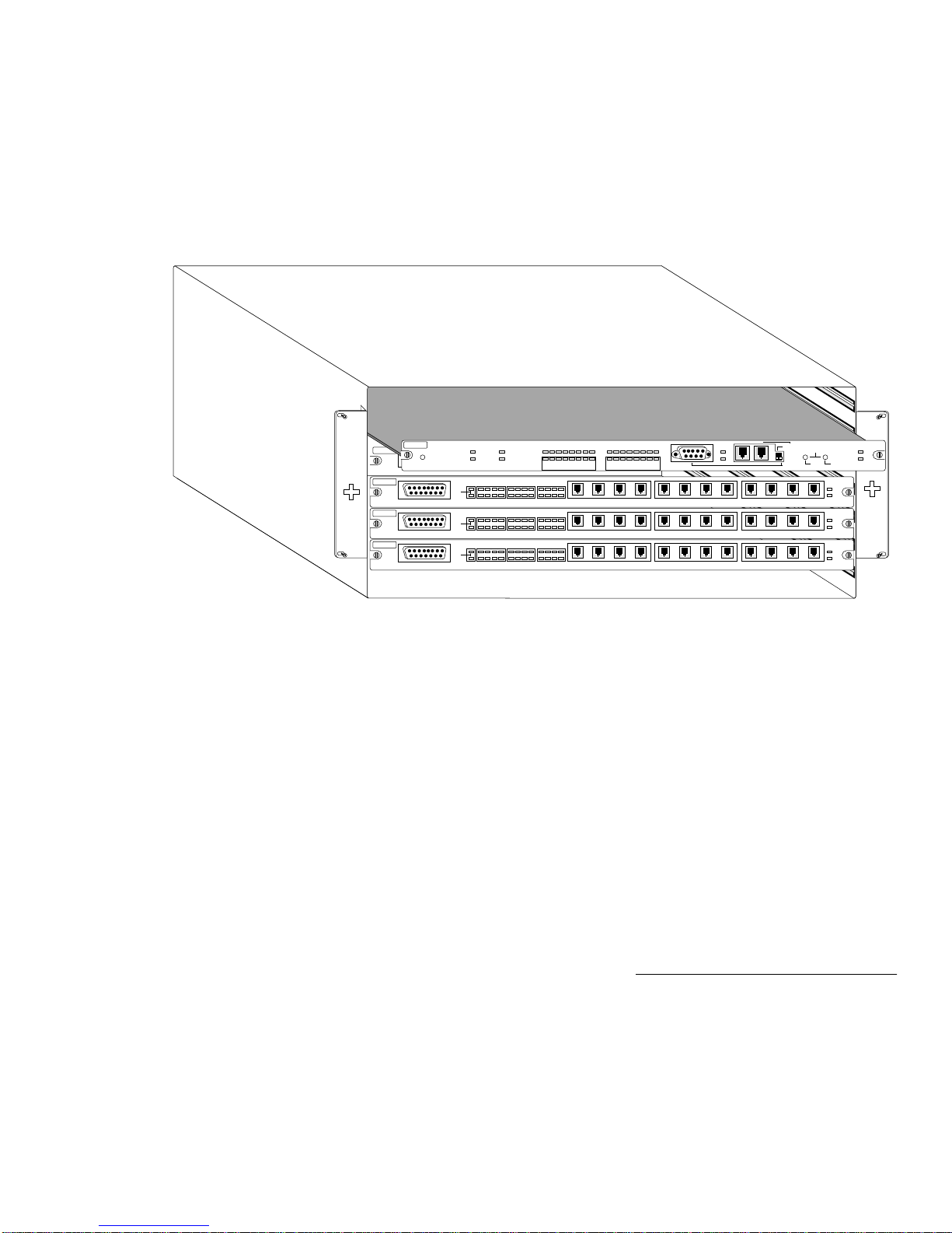
Introducing the Network Management Module
With the NMM’s Segment Control buttons,you can manually iso-
late any AH
2072
NMM or NetStacker module,or assign it to either
of the chassis’two segments.This can also be accomplished
remotely using AsantéView In-Band and Out-of-Band software.
Segment Control allows you to monitor and control both seg-
ments of the AsantéHub
2072
and its repeater modules.
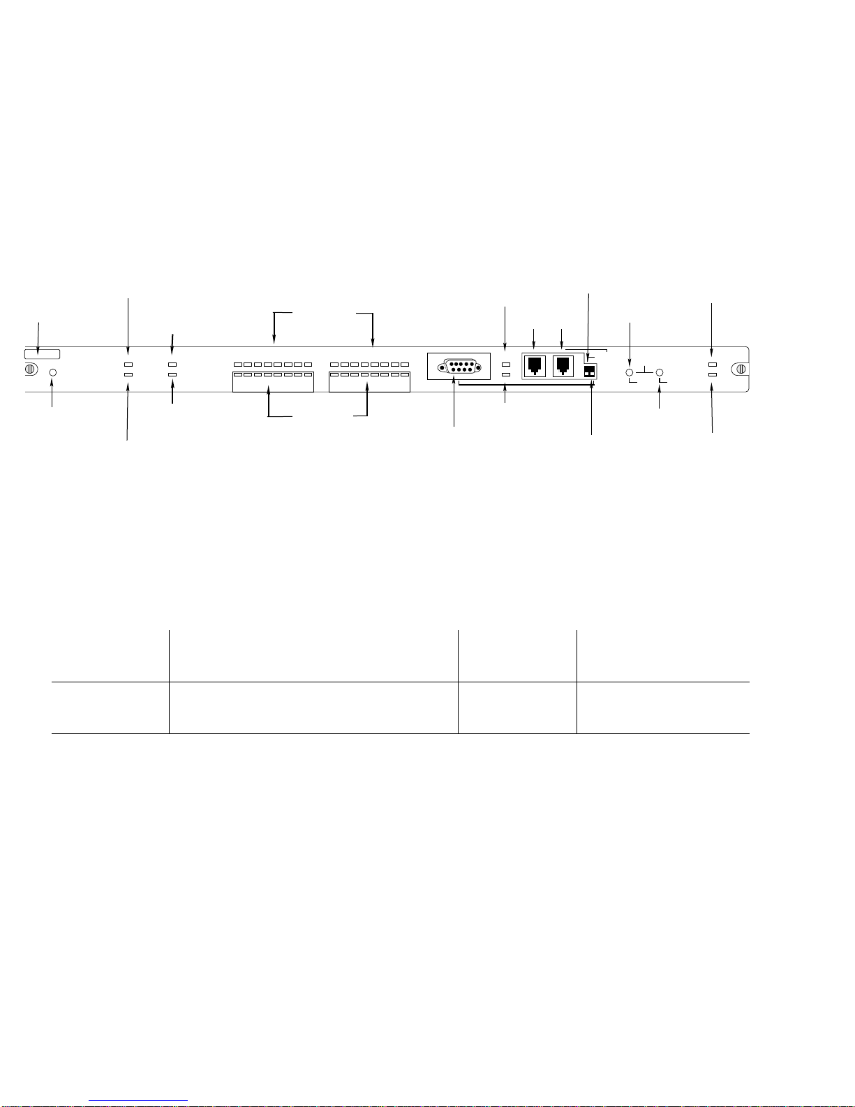
The module’s RS232 port and its AsantéView Management Station
(AMS) Link offer remote (out-of-band) network management con-
trol.With these two connections and an AsantéView Management
Station,you can gather statistics and set parameters for as many as
twelve daisy-chainedAsanté hubs.You can also use the RS232 port
as a local management port.Used in this way with terminal emula-
tion software,you can gather statistics and set parameters for an
individualAsanté hub.
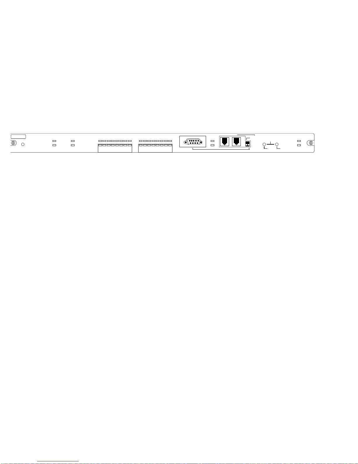
LEDs for both Ethernet segments are displayed on the NMM front
panel or can be viewed from an AsantéView Management Station.
The LEDs display many types of traffic statistics,such as late colli-
sions,misalignments,fragments,and short events,as well as seg-
ment utilization and collision percentages in bar graph form.
The NMM is easy to upgrade because it has Flash EEPROM mem-
ory.To upgrade to the latest hub software (image code),download
the NMM’s microcode upgrades from an AsantéView Management
Station or from a third party TFTP server directly through the net-
work.See the appropriate AsantéView User’s Guide or third-party
server documentation for more information on the upgrade proce-
dure.
The AsantéHub
2072
MIB is a text file distributed byAsantéTech-
nical Support.The file can also be obtained using anonymous FTP
(FileTransfer Protocol) fromAsanté’s Internet accessible FTP
server (see "AsantéTechnical Support" on page 2 for more infor-
mation).
For MIB compilation instructions,refer to your management con-
sole’s documentation.