manuals.online logo
Brands
  1. Home
  2. •
  3. Brands
  4. •
  5. Asante
  6. •
  7. Network Router
  8. •
  9. Asante IntraSwitch 5324MT User manual

Asante IntraSwitch 5324MT User manual

1.Place the IntraSwitch on a flat surface or in an equipment rack.
▲Important:See “Rack Mounting/Desktop Placement”on the reverse side of
this card for information on securing the switch in an equipment rack or preparing
it for desktop placement.
2.Plug one end of the supplied power cord into the connector on the left side of the
unit’s rear panel.
3.Plug the other
end into a
grounded
AC outlet.
4.Turn on the power
switch (located on the left
side of the unit’s rear panel).
Make sure the front-panel LEDs
blink once and the power light is on.
5.Power off the IntraSwitch.
After the power connection is checked, the switch is ready to be connected to the
network.Proceed to Step 2, “Connect to the Network.”
Quick Installation Guide
IntraSwitch 5324MT
After the IntraSwitch 5324MT is connected to the network and is powered on, you can
configure it for management capabilities, as described in the “Installation”chapter of the
IntraSwitch 5324 User’s Manual.
All other procedures involved in the management and monitoring of the IntraSwitch
5324MT are identical to those for the IntraSwitch 5324 with RJ-45 connectors.Refer to
your IntraSwitch 5324 User’s Manual for details.
1.Make sure the IntraSwitch 5324MT is not powered on.
2.Pull the loose ends of the two velcro straps away from the port interfaces on
the front of the IntraSwitch 5324MT.
3.Press each connector into place carefully, making sure you do not bend any of the
connector pins.
4.Depending on whether you a have“T”type connector or a right-angle connector
on your cable, you will need to follow one or the other of the following methods
to secure the connector in place.
Attaching “T” Type Connectors to the 5324MT
If you have“T”type connectors on your cables, screw in the screws provided with them,
or use the wing brackets attached to the 5324MT to secure the connectors, as shown
in the illustration on the top left.
2 Attaching the RJ-21 connectors
1 Plug In and Check Power Connection
Additional materials required:
•Refer to Step #2 (“Connect to the Network”) to determine the cables you need
for connecting the IntraSwitch to the network.
•Phillips screwdriver (#2) for rack-mounting the switch.
Package Contents
The IntraSwitch 5324MT is shipped with the following items:
(1)IntraSwitch 5324MT Ethernet switch
(4)Rubber pads for desktop placement
(1)Power cord
(2)Rack-mounting brackets
(12) Standard Phillips screws for
attaching rack-mounting brackets
Overview
The Asanté IntraSwitch 5324MT is a high-performance, manageable Ethernet switch
that offers 24 10Base-T ports, one 10/100TX port, and two optional Media Independent
Interface (MII) expansion slots.the 5324MT is a special version of the IntraSwitch 5324
designed to accomodate RJ-21 (also known as 50 pin Telco) connectors.In all other
aspects than the connectors, the 5324MT is identical to the IntraSwitch 5324.Refer to
the IntraSwitch 5324 User’s Manual for all procedures and system requirements.
The only difference between the 5324MT and the standard 5324 IntraSwitch is in the
design of the port connections.Instead of having to attach 24 separate push-in RJ-45
connectors, you only need to attach two 50 pin connectors.
(1)CD containing IntraSpection™ Web-
based network management software
(1)IntraSwitch User’s Manual
(1)Quick Installation Guide (this card)
3Management and Monitoring Capabilities
▲Skip this step if you plan to use the IntraSwitch as an unmanaged switch.
To use the IntraSwitch 5324MT as a managed switch, it must be configured with
an IP address.This can be accomplished in one of two ways:
•automatically using BootP (default)
•manually via the Console port
BootP Configuration
The IntraSwitch 5324MT is shipped with BootP support.BootP allows the switch to be
automatically configured with an IP address when the switch is connected to the network
and is powered on, if your network contains a BootP server configured with available,
valid IP addresses.
1. Make sure your network has a BootP server configured with a valid IP address
entry for the IntraSwitch 5324MT.
2. When the IntraSwitch is connected to the network and is powered on,
it automatically transmits a BootP request across the network (up to 10 times)
until it receives a valid IP address from the BootP server.
3. After an IP address is received, the switch can be managed via in-band access.
Refer to Chapter 4 of the User’s Manual for more information.
If an IP address is NOT received, the switch will need to be manually configured
with an IP address via the Console port.See “Console Configuration”on back.
3a Configure for Management
2A MII ports Cabling Procedures
The two RJ-21 10Base-T ports and one 10/100 port each have an MDI (media dependent
interface), the IEEE 10Base-T standard for unshielded twisted-pair cable) interface.
The 10/100 port and 10 switched put are cabled for straight through connection
to the client workstation.
The optional MII expansion slots allow for the connection of 10/100TX, 100Base-FX,
or 10Base-FL (fiber) ports.
To connect a 10/100TX module to a network station:
•Use a Category 5 UTP cross-over cable with RJ-45 connectors.
To connect a 10/100TX module to a repeater/hub:
•Use a Category 5 UTP straight-through cable with RJ-45 connectors.
To connect a 10/100TX module to a repeater/hub’s uplink port:
•Use a Category 5 UTP cross-over cable with RJ-45 connectors.
To connect a 100Base-FX module to a repeater/hub or to a network station:
•Use a dual 62.5/125 micron graded–index multimode fiber-optic cable fitted
with a dual SC connector.
To connect a 10Base-FL module to a repeater/hub or to a network station:
•Use a dual 62.5/125 micron graded–index multimode fiber-optic cable fitted
with a dual ST connector.
Attaching Right-angle Connectors to the 5324MT
If you have one “T”type and one right-angle connector, attach the “T”connector to
the left socket and the right-angle connector to the right socket.
5.Power on the IntraSwitch 5324MT.
Technical Specifications
Network Management SNMP-compatible management software, HTTP
management software, Telnet software
ConnectorsRS-232 (DB-9, female), RJ-45 (10/100Base-TX),
RJ-21 (10/100Base-TX),
MII (Media Independent Interface)
SpanningTree SupportIEEE 802.1d
MAC AddressTable Size1024
Dimensions Width: 17.1 inches (434.3 mm)
Height: 2.25 inches (57.2 mm)
Depth: 14.5 inches (368.3 mm)
Weight 11 pounds (5 kilograms)
Power Specifications
Voltage Range: 100 to 250 VAC
Frequency Range: 50/60/440 Hz
Maximum current range: 1.6A
Environmental Specifications
Temperature Operating:0°to 40°C
Relative Humidity Operating:5% to 85% (non-condensing)
Standards Compliance MIB II, RMON (4 groups:1,2,3,9), BootP, DHCP,
IEEE 802.3, IEEE 802.3u, IEEE 802.1d
Safety UL, CSA, VDE, TUV
Emissions FCC Class A, EN55022, CE
06-00437-00
LEDs
Asking for Assistance
Technical Support Hours:6:00 a.m.to 5:00 p.m.Pacific Standard Time, Monday-Friday
For troubleshooting tips, refer to Appendix A in the IntraSwitch 5324 User’s Manual.
1. Using a straight-through RS-232 cable with a 9-pin male D-subminiature plug at
one end, connect a stand-alone terminal or a PC with a terminal emulator to the
Console port on the IntraSwitch.
2. Make sure both units are powered on.
If using a PC with a terminal emulator, make sure it is configured with the following
terminal settings:
•Bits Per Second:9600 •Stop Bits: 1
•Data Bits: 8•Flow Control Hardware:None
•Parity:None
3. After connecting to the switch, the Local Management Interface Main Menu appears.
4. Type cto open the Configuration Menu.The “Enter Password”prompt appears.
5. Type Asante at the “Enter Password”prompt. The password is case sensitive.
6. Press return.The Configuration Menu appears.
7. Type ito open the TCP/IP Parameter Menu.The TCP/IP Parameter Menu appears.
8. Type ito select the option “Set IP Address.”
9.Type a valid IP address for the IntraSwitch at the prompt, then press return.
▲Depending on your network configuration, you may also need to set subnet
mask and default router information for the IntraSwitch.See “Configure TCP/IP
Parameters”in Chapter 4 of the User’s Manual for details.
10.Type qto return to the Configuration Menu.
To install an MII module:
1. Unscrew the metal cover from the front of an MII expansion slot on the
IntraSwitch’s back panel using a small Phillips screwdriver.
2. Align the bottom of an MII module with the rails on the inside of the expansion slot.
3. Slide the MII module into the expansion slot until it stops, then push the module
in until it seats with the connector.
4. Screw the module into place using the screw that came with your MII module
(this secures the module’s connection).
After the MII module is installed, connect the port to a network device.
5 MII Expansion Slots
The IntraSwitch has two optional Media Independent Interface (MII) expansion slots
on the switch’s back panel which allow for the addition of various types of media
access modules, including 10/100 TX, 100Base-FX, and 10Base-FL.
The MII modules are sold separately and comply with IEEE 802.3 and 802.3u
(10/100Base-T and 100Base-FX) specifications.
3b Console Configuration
The IntraSwitch can be installed in a standard 19-inch EIA RS-310C equipment rack.
The switch can also be placed on a horizontal surface with support capabilities of
11 pounds (5 kilograms).
Equipment Rack Installation
To install the IntraSwitch in an equipment rack:
1.Mount one rack bracket (supplied) on each side of the switch’s chassis with the
screws provided.
2.Place the IntraSwitch in the equipment rack.
3.Use the four remaining screws to secure the switch by its mounting brackets to the
equipment rack.
▲Important:Make sure the switch is supported until all four remaining screws for
each bracket are installed.Failure to do so could cause the switch to fall, resulting in
personal injury or damage to the unit, or both.
4A Desktop Placement
The IntraSwitch has four rubber self-adhesive feet that can be applied to the bottom
of the chassis to enable desktop/free-standing installation of the unit.
1.Turn the switch over so that the bottom of the chassis faces up.
2. Peel the protective backing off of each rubber foot.
3. Position each rubber foot over the recessed areas near the four corners of the switch.
4. Press each rubber foot into place.
5. Place the switch on a horizontal surface with a minimum area of 17.1" x 14.5".
Telephone (800) 622-7464
Fax (801) 566-3787
BBS (408) 432-1416
FTP Archiveftp.asante.com
Internet mail support@asante.com
World Wide Web site www.asante.com
Here’s how to reach Asanté Technical Support.
METAL COVER
LED Color Meaning
Power green The IntraSwitch is receiving electrical power.
100Mbps green 10/100 port or an installed MII expansion port is
operating at 100Mbps speed.
Note:These LEDs only function with ports capable of
operating at 100Mbps speed (i.e., the 10/100 port or
an installed MII module).
Max Util amber The corresponding port’s receive buffer is full
(maximum utilization).
FDP/Col amber Indicates full duplex mode on the 10/100 port or
on an installed MII expansion port.
Indicates a collision at the switching port for those
ports operating in half-duplex mode.
Data green Traffic activity is occurring on a port (transmit [TX] or
receive [FIX]).
Link green A node or other network device is properly connected
to the corresponding port.
4 Rack Mounting/Desktop Placement

Other Asante Network Router manuals

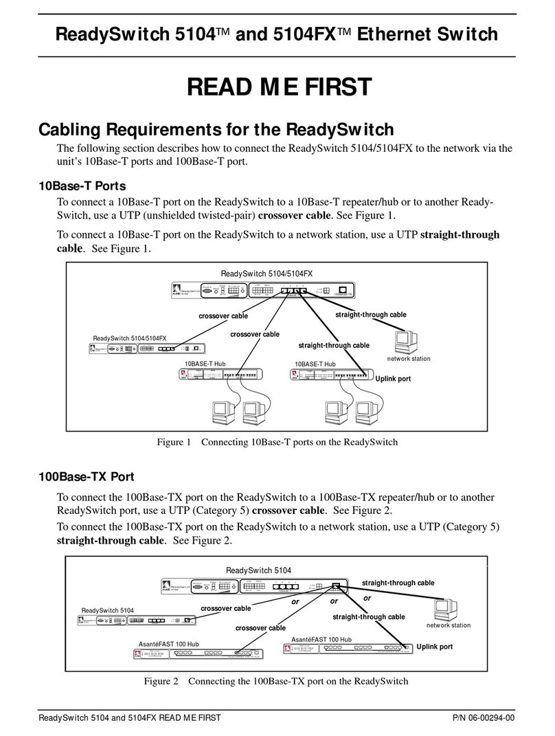
Asante ReadySwitch 5104 Manual

Asante

Asante ReadySwitch 5104 Manual

Asante FriendlyNET GX5-424W User manual

Asante

Asante FriendlyNET GX5-424W User manual

Asante IntraCore IC3624PWR User manual

Asante

Asante IntraCore IC3624PWR User manual

Asante FriendlyNET FS4005P User manual

Asante

Asante FriendlyNET FS4005P User manual

Asante FriendlyNET GX5-424W User manual

Asante

Asante FriendlyNET GX5-424W User manual

Asante IntraCore 8000 User manual

Asante

Asante IntraCore 8000 User manual

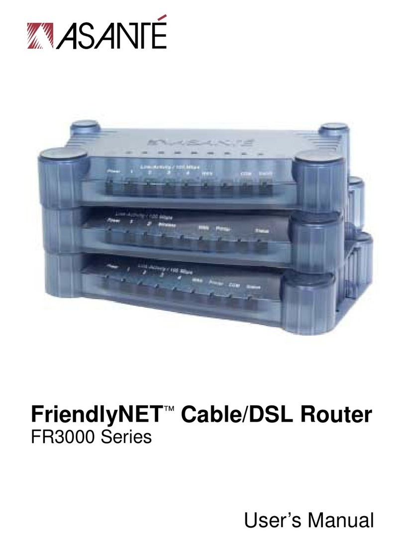
Asante FriendlyNET FR3000 Series User manual

Asante

Asante FriendlyNET FR3000 Series User manual

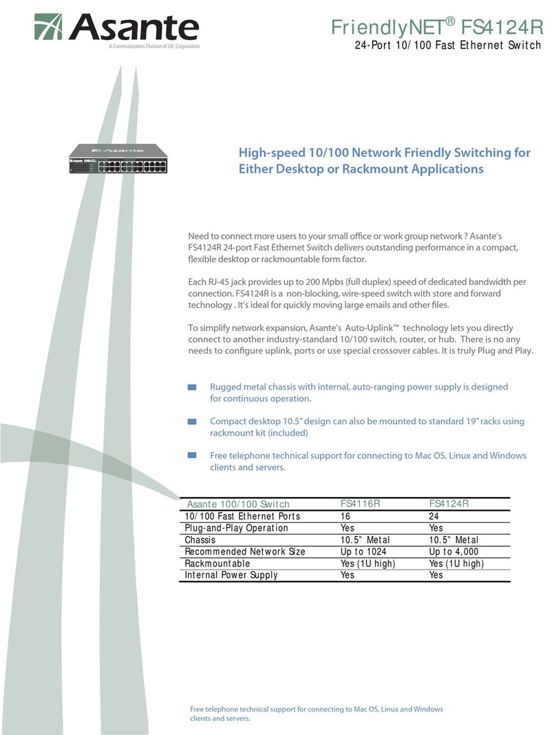
Asante FriendlyNET FS4124R User manual

Asante

Asante FriendlyNET FS4124R User manual

Asante Asante FriendlyNET FS4116R User manual

Asante

Asante Asante FriendlyNET FS4116R User manual

Asante FS4002E/FS4004E User manual

Asante

Asante FS4002E/FS4004E User manual

Asante Asante FriendlyNET FS4124R User manual

Asante

Asante Asante FriendlyNET FS4124R User manual

Asante IntraCore 40240 User manual

Asante

Asante IntraCore 40240 User manual

Asante FriendlyNET GX5-424W User manual

Asante

Asante FriendlyNET GX5-424W User manual

Asante FriendlyNet FS3208 User manual

Asante

Asante FriendlyNet FS3208 User manual

Asante FriendlyNET FR1104-G User manual

Asante

Asante FriendlyNET FR1104-G User manual

Asante 6000 Series User manual

Asante

Asante 6000 Series User manual

Asante IntraCore 6524 User manual

Asante

Asante IntraCore 6524 User manual

Asante FriendlyNet FS4004DS User manual

Asante

Asante FriendlyNet FS4004DS User manual

Asante IntraStack 6014DSB User manual

Asante

Asante IntraStack 6014DSB User manual

Asante FriendlyNET VR2004 Series User manual

Asante

Asante FriendlyNET VR2004 Series User manual

Asante FriendlyNET GX5-2400W User manual

Asante

Asante FriendlyNET GX5-2400W User manual

Asante IntraStack 6014DSB Manual

Asante

Asante IntraStack 6014DSB Manual

Asante FriendlyNET FS4008P User manual

Asante

Asante FriendlyNET FS4008P User manual

Asante FriendlyNET FS4116R User manual

Asante

Asante FriendlyNET FS4116R User manual

Popular Network Router manuals by other brands

Motorola VL-RISC MCF5202 user manual

Motorola

Motorola VL-RISC MCF5202 user manual

Ruijie RSR10 Series Hardware installation manual

Ruijie

Ruijie RSR10 Series Hardware installation manual

Comet Labs GS5+ user manual

Comet Labs

Comet Labs GS5+ user manual

AVM FRITZ!Box 6820 LTE manual

AVM

AVM FRITZ!Box 6820 LTE manual

Asus ZenWiFi AC Mini CD6 Series quick start guide

Asus

Asus ZenWiFi AC Mini CD6 Series quick start guide

Avaya SR 2330 Task based guide

Avaya

Avaya SR 2330 Task based guide

Maipu MP2900-04-AC installation manual

Maipu

Maipu MP2900-04-AC installation manual

RouterBOARD RB911 Series user manual

RouterBOARD

RouterBOARD RB911 Series user manual

WM Systems M2M Router PRO 4 user manual

WM Systems

WM Systems M2M Router PRO 4 user manual

Fritz!Box 7590 manual

Fritz!Box

Fritz!Box 7590 manual

Shenzhen Hongdian Technologies H8951-LQA user manual

Shenzhen Hongdian Technologies

Shenzhen Hongdian Technologies H8951-LQA user manual

Cabletron Systems DELST-UI Management guide

Cabletron Systems

Cabletron Systems DELST-UI Management guide

Cisco Catalyst 2928 Software configuration guide

Cisco

Cisco Catalyst 2928 Software configuration guide

CP TECHNOLOGIES IFP-0501 Quick installation guide

CP TECHNOLOGIES

CP TECHNOLOGIES IFP-0501 Quick installation guide

SMC Networks EZ Connect g Quick installation guide

SMC Networks

SMC Networks EZ Connect g Quick installation guide

Asus RT-AX88U quick start guide

Asus

Asus RT-AX88U quick start guide

D-Link Airspot DSA-3100 Quick installation guide

D-Link

D-Link Airspot DSA-3100 Quick installation guide

Aastra TA710i Hardware installation guide

Aastra

Aastra TA710i Hardware installation guide

manuals.online logo
manuals.online logoBrands
  • About & Mission
  • Contact us
  • Privacy Policy
  • Terms and Conditions

Copyright 2025 Manuals.Online. All Rights Reserved.