ASBER AEPO-24 Simple manual

––
PIZZA OVEN
Manual Instructions
AEPO-24 , AEP0-24 S , AEPO 36, AEPO 36 S
Manual instructions
Installation and Operation
Manueltalimatları
Kurulum ve Çalıştırma
Manual de instrucciones
Uso y mantenimiento
Manuel d’instructions
Installation et fonctionnement
Bedienungshinweise
Installation und Betrieb
Manual do instruções
Instalação e Operação
Ręczny
Obsługa i konserwacja
ES
EN
DE
TK
FR
PT
PL

ii
1.1 IMPORTANT SAFETY INFORMATION
All equipment manufactured by ASBER CORP. is for use with the type of gas specified on the rating plate and
for installation will be in accordance with National Fuel Gas Code ANSI Z223.1 (latest edition)
FOR YOUR SAFETY: Do not store or use gasoline or other flammable vapors
or liquids in the vicinity of this or any other appliance.
MESURE DE SÉCURITÉ: Ne pas entreponer ni utiliser d´essence ni autres
vapeurs ou liquides inflammables á proximité de cet appareil ou de tout
autre appareil.
Instructions to be followed in the event the user smells gas must be posted in a prominent location in the kitchen
area. This information shall be obtained from the local gas supplier.
WARNING: Improper installation, adjustment, alteration, service or
maintenance can cause property damage, injury or death. Read the
installation, operating and maintenance instructions thoroughly before
installing or servicing this equipment.
MISE EN GARDE: Une installation, un réglege, une modification, ine
réparation ou un entretien inadécuat peut provoquer des dommager
matériels, des blessures ou la mort. Lisez sougneusement les instructions
d´installation, d´utilisation et d´entretien avant d´installer ou de reparer cet
équipement
PLEASE RETAIN THIS MANUAL FOR FUTURE REFERENCE.

iii
INDEX
1.1 IMPORTANT SAFETY INFORMATION .......................................................................................................ii
MACHINE INTRODUCTION.......................................................................................................................................4
1.2 INTRODUCTION TO MACHINE & MODELS...............................................................................................4
INSTALLATION..........................................................................................................................................................4
2.1 Transport, handling, unpacking, location................................................................................................4
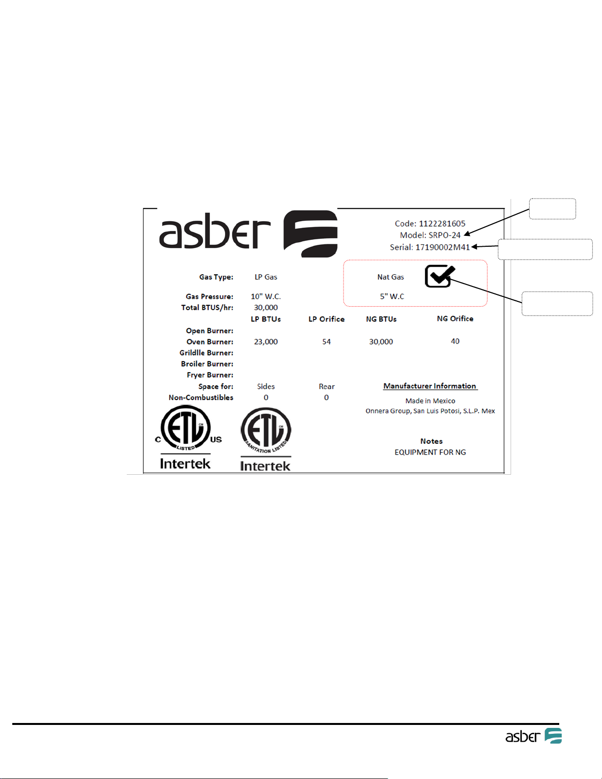
2.2 Manufacturer’s identification label description......................................................................................5
2.3 Installation and assembly ........................................................................................................................5
2.3.1 UNCRATING .....................................................................................................................................6
2.3.2 INSTALLATION OF LEGS (IF APPLICABLE).........................................................................................6
2.4 Gas Connections ......................................................................................................................................6
2.4.1 MANUAL SHUT OFF VALVE..............................................................................................................7
2.4.2 PRESSURE REGULATOR....................................................................................................................7
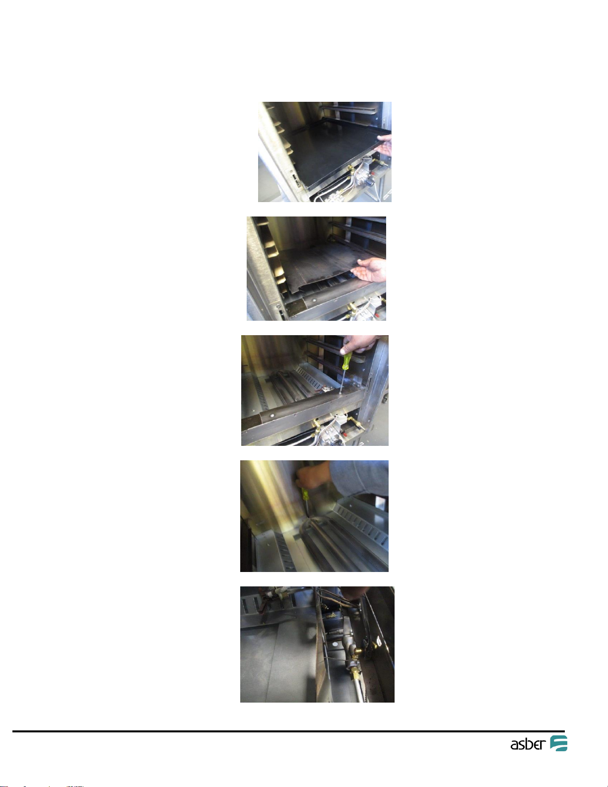
2.4.3 THIS APPLIANCE IS EQUIPPED FOR NATURAL GAS..........................................................................7
2.5 Location ...................................................................................................................................................9
2.6 AIR SUPPLY & VENTILATION ....................................................................................................................9
OPERATION........................................................................................................................................................... 10
3.1 General information. ............................................................................................................................ 10
3.2 LIGHTING INSTRUCTIONS ..................................................................................................................... 10
3.3 DAILY SHUT-DOWN............................................................................................................................... 10
MAINTENANCE ..................................................................................................................................................... 11
4.1 CLEANING ............................................................................................................................................. 11
4.1.1 DAILY............................................................................................................................................. 11
4.1.2 STAINLESS STEEL PARTS................................................................................................................ 11
TROUBLE SHOOTING ............................................................................................................................................ 13
WARRANTY ........................................................................................................................................................... 14
5.1 Limited Warranty.................................................................................................................................. 14

4
MACHINE INTRODUCTION
1.2 INTRODUCTION TO MACHINE & MODELS
All equipment manufactured by ASBER. are for use with the type of gas specified on the rating plate and for
installation will be in accordance with National Fuel Gas Code ANSI Z223.1 (latest edition)
INSTALLATION
2.1 Transport, handling, unpacking, location.
2.2 Manufacturer’s identification label description.
2.3 Installation and assembly.
2.4 Gas Connections
2.1 Transport, handling, unpacking, location
Upon receiving your new ASBER Equipment, check the package and the machine for any damages that may
have occurred during transportation. Visually inspect the exterior of the package. If damaged, open and inspect
the contents with the carrier. Any damage should be noted and reported on the delivering carrier’s receipt.
In the event that the exterior is not damaged, yet upon opening, there is concealed damage to the equipment
notify the carrier immediately. Notification should be made verbally as well as in written form. Request an
inspection by the shipping company of the damaged equipment. Retain all crating material until inspection has
been made. Finally, contact the dealer through which you purchased the unit.

5
2.2 Manufacturer’s identification label description
Information on this plate includes the model, serial number, BTU / hour input of the burners operating gas
pressure in inches WC, and whether the appliance is orifices for natural or propane gas.
When communicating with factory about a unit or requesting for special parts or information,
Rating plate data is essential for proper identification.
ASBER COOKING APPLIANCES MUST BE CONNECTED ONLY TO THE TYPE OF GAS IDENTIFIED ON
THE RATING PLATE
2.3 Installation and assembly
SHIPPING DAMAGE CLAIM PROCEDURE
The equipment is inspected and crated by skilled personnel before leaving our factory. The transportation
company assumes full responsibility for safe delivery upon acceptance of this equipment. If shipment arrives
damaged:
Visible loss or damage: Note on freight bill or express delivery and signed by person making delivery.
File claim for damages immediately: Regardless of extent of damages.
Concealed loss or damage: If damage is noticed after unpacking, notify Transportation Company
immediately and file “Concealed Damage “claim with them. This should be done within (15) days from
date of delivery made to you. Retain container for inspection.
Model
Gas Type
Serial Number

6
2.3.1 UNCRATING
Cut and remove the outer packaging. Cut the (4) clamps that hold the equipment to the skid lift the unit off the
skid.
2.3.2 INSTALLATION OF LEGS (IF APPLICABLE)
LEGS ASSEMBLY:
The Appliance could be mounted on a table or counter noncombustible.
Mount Legs on bottom of product, the appliance may be further leveled with adjustment in the foot of
the leg.
Legs may provide as accessories.
2.4 Gas Connections
The gas supply (service) line must be the same size or greater than the inlet line of the appliance. SI appliances
use a ¾” NPT inlet.
Pipe joint compound must be resistive to Natural or LP gas.
For equipment using propane gas do not install supply lines with a diameter less than ½ under any
circumstances.
All connections must be tested with a soapy water solution before lighting any pilots.

7
The appliance shall be connected to the fuel gas for which it was designed. No attempt shall be made to convert
the appliance from the gas specified on the rating plate for use with a different gas without consulting the
installation instructions, the serving gas supplier, or the appliance manufacturer for complete instructions.
2.4.1 MANUAL SHUT OFF VALVE
This installer supplied valve must be in the gas service line ahead of the appliance regulator in the gas
stream and in a position accessible in the event of an emergency.
2.4.2 PRESSURE REGULATOR
Commercial cooking equipment must have a pressure regulator on the incoming service line for safe and
efficient operation; the gas pressure regulator supplied by ASBER must be installed at the gas inlet of
each piece of equipment.
The regulators supplied along with ASBER appliances, will have 3/4” inlet/outlet openings and are
adjusted at the factory for 5” WC (natural gas) or 10” WC (propane gas) depending on customer’s
ordering instructions.
Prior to connecting the regulator, check the incoming line pressure, as these regulators can only
withstand a maximum pressure of ½” PSI (14” WC). If the line pressure is beyond this limit, a step down
regulator will be required.
The arrow shown on the bottom of the regulator body shows the gas flow direction, it should point
downstream to the appliance. The BLUE air vent cap on the top is part of the regulator and should not
be removed.
Qualified service personnel only with the proper equipment should make any adjustments to the regulator.
2.4.3 THIS APPLIANCE IS EQUIPPED FOR NATURAL GAS.
This appliance is equipped with orifices sized for operation with natural gas.
For conversion to LP (PROPANE) gas see instruction plate in the appliance. Gas conversion must be
performed by qualified or authorized personnel. Orifices necessary for LP (PROPANE) and regulator for
conversion are provided on accessory box.

8
Failure to install the pressure regulator will void the appliance warranty
2.4.3.1 L.P. gas conversion:
Step one; Remove oven bottom
Step 2; Remove deflector
Step 3; Take off top shield from oven
Step 4; Pull of oven burner
Step 5; Retire and change orifice for L.P.

9
Assembly all components, reverse these instructions.
2.5 Location
• Installation of the equipment should be performed by qualified, certified, and authorized personnel who are
familiar and experienced with local installation codes.
• Before Installation please read instructions completely and carefully.
• Do not remove permanently affixed labels, warnings or plates from the product.
• Please observe all local and national codes and ordinances
• Installation must conform with local codes, or in the absence of local codes, the National
Fuel Gas Code, ANSI Z223.1 (latest edition)
• The appliance must be isolated from gas supply piping system, by closing its individual manual shut off valve
during any pressure testing of the gas supply piping system at test pressure equal to or less than ½ psi (3.45kpa)
CLEARANCES
The appliance area must be kept free and clear of all combustibles
SPO Series products are for installation in Non-Combustible locations only, Installation in combustible location is
not allowed.
NON COMBUSTIBLE
SIDES
0
REAR
0
FLOOR
0
2.6 AIR SUPPLY & VENTILATION
The area in front of, around and above the appliance must be kept clear to avoid any obstruction of the flow of
combustion and ventilation air.
Adequate clearance must be maintained around the appliance for easy servicing. Provision should be made for
any commercial, heavy-duty cooking appliance exhaust combustion waste products to the outside of the building.
Usual practice is to place the appliance under an exhaust hood, which should be constructed in accordance to the
local codes. Strong exhaust fans in this hood or in the overall air conditioning system can produce a slight vacuum
in the room and / or cause air drafts, either of which can interfere with the pilot or burner performance and could
be difficult to diagnose. Air movement should be checked during installation. Air openings or baffles may have to
be provided in the room, if pilot or burner outage problem persists.

10
OPERATION
3.1 General information.
3.2 Lighting Instructions.
3.3 Daily Shut-Down.
3.1 General information.
Operation of this equipment must be performed by qualified or authorized personnel who have read and are
familiar with the functions of the equipment.
3.2 LIGHTING INSTRUCTIONS
1. Depress the red button on the pilot safety valve.
2. Wait for five seconds.
3. Push piezo electric spark ignition system.
4. Release the pilot gas valve.
5. If the pilot does not stay lit, repeat step 2 and 3.
6. Turn gas valve to “on” position.
7. Turn the thermostat to set the desired temperature.
8. For complete shutdown turn thermostat and manual valve to “off” position.
9. Wait 5 minute after complete shutoff period before the appliance is relighted
NOTE: It may be necessary to relight the pilot several times until the lines are purged of any trapped air and a
constant gas flow is attained.
3.3 DAILY SHUT-DOWN
At the end of the day, turn the gas tap dial on the combination gas valve and the thermostat to OFF position.
WARNING
Hot surfaces can cause severe burns. Use caution when operating the oven.
Do not attempt to move the oven when is hot.
Do not go near the area directly above the flue when oven is operation.
Severe burns may be caused.

11
MAINTENANCE
4.1 Cleaning
4.1 CLEANING
For continued performance efficiency and longevity of your Fryer it is essential to carry out a good maintenance
program.
4.1.1 DAILY
OVENS
On initial installation, turn the oven to 250°F degrees and operate for about 1 hour, then reset the
thermostat to its maximum and operate for another hour. This will drive off any solvents remaining in the
unit. At the end of this second hour, turn the thermostat OFF, open the door and allow the unit to cool.
Oven should then be thoroughly washed using hot, soapy water before being used.
4.1.2 STAINLESS STEEL PARTS
Do not use steel wool, abrasive cloths, cleansers or powders to clean stainless steel surfaces. All stainless steel parts
should be wiped regularly with hot soapy water during the day and a stainless steel liquid cleaner at the end of the day.
To remove encrusted materials, soak in hot water to loosen the material, and then use a wood or nylon scraper. NOT
USE a metal knife, spatula, or any other metal tool to scrape stainless steel. Scratches are almost impossible to remove.
Contact the factory, factory representative or a local service company to perform all Maintenance and
Service Repairs.

12
4.1.3 Take off the oven door:
STEP 1.- Place in this way the assembler component in
both hinges (you can find 2 pieces of it in carton legs
box)
STEP 2.- Hold on both hinges of door
with your hands.
STEP 3.- Raise the door until it forms a 45
degrees’angle.
STEP 4.-Pull the door towards you and up.
For put again the oven door, reverse these
instructions.

13
TROUBLE SHOOTING
PROBLEM
PROBLEM CAUSE
SOLUTION
BURNER AND/OR PILOTS
NOT TURN ON
GAS SUPPLY TO COOKING
EQUIPMENT IS OFF
TURN ON GAS SUPPLY
UNIT PRODUCING CARBON
DEPOSITS
GAS TYPE
VERIFY CORRECT GAS
GAS SUPPLY PRESURE
CONTACT LOCAL GAS
SUPPLIER
PRIMARY AIR NOT
ADJUSTED PROPERLY
ADJUST AIR SHUTTER
ORIFICE TOO BIG
VERIFY ORIFICE SIZE
PILOT WILL NOT REMAIN LIT
PILOT FLAME NOT
ADJUSTED
ADJUST PILOT FLAME
DRAFT CURRENTS NEAR
EQUIPMENT
FIX DRAFT
NOT ENOUGH VENTILATION
CONTACT HVAC
CONTRACTOR
DEBRIS OR GREASE
CLOGGING PILOT BURNER
CLEAN DEBRIS AND GREASE
FROM PILOT BURNER
EXCESSIVE FLARE-UP
OVERLOAD OF OIL AND
LEFTOVERS
CLEAN AND PREPARE PAN
NOT HEATING PROPERLY
ORIFICES DIRTY/CLOGGED
CLEAN ORIFICE, MAKE SURE
THERE IS NO RESTRICTION
IN THE ORIFICE BURNER
LOW GAS PRESSURE
INCREASE GAS PRESSURE
TO 5” WC (NAT) OR 10” WC
(L.P.)
GRATES DIRTY/CLOGGED
CHECK AND CLEAN TOP
GRATES
IF THE VENTILATION IS TO
STRONG IT WILL DRAFT
HEAT FROM THE
COOKING/BROILING
SURFACE
CALL HVAC CONTRACTOR

14
WARRANTY
5.1 Limited Warranty
ASBER warrants its new product(s) to be free from defects in material and workmanship for a period of one (1) year from the original date of
installation not to exceed 15 months from date of shipment from our factory. Equipment sold and installed for residential use, or outside the
continental US is excluded from this warranty.
This warranty is limited to product(s) sold to the original commercial user. The liability of ASBER is limited to, at ASBER’s option, the repair or
replacement of any part (ground shipping only) found by ASBER to be warranted herein. ASBER shall bear the normal labor charges for repair of
replacement to the extent that such repair or replacement is performed within (2) two hours or up to 100 miles total of the office of an authorized
service agency, within the continental US and during regular (straight time) hours. Travel outside of the (2) two hours or 100 miles, and any work
performed at overtime or weekend rates would be the responsibility of the owner/user. Defective parts must be returned to ASBER, freight pre-paid,
for Warranty inspection.
ASBER assumes no responsibility for any product not installed properly in accordance with the instructions supplied with the equipment by an
authorized representative. Any equipment which has been modified by unauthorized personnel or changed from its original design is not covered
under this warranty. Furthermore, ASBER assumes no obligation for any product which has been subject to misuse, abuse or hard chemicals. Normal
maintenance as outlined in the instructions is the responsibility of the owner-user and is not a part of this warranty. Normal parts wear and
maintenance is also not covered by this warranty. This warranty is in lieu of any other agreement, expressed or implied, and constitutes the only
warranty of ASBER with respect to the product.
This states the exclusive remedy against ASBER relating to the product(s) whether in contract or in tort or under any other legal, theory, and whether
arising out of warranties, representations, instruction, installation or defects’ from any cause.
ASBER shall not be liable whether in contract or in tort or under any other legal theory for loss of revenue or profit, or for any substitute use or
performance or for incidental, indirect, special or consequential damages, or for any other loss or cost of similar type.
Proper installation, initial check out, air shutter adjustments, or normal maintenance such as lubrication, adjustment or calibration of controls is the
responsibility of the dealer, owner-user or installing contractor and is not covered by this warranty.
Parts warranty cover –ASBER warrants all new machine parts produced authorized by ASBER to be free from defects in material and workmanship
for a period of 90 days from the Warranty Commencement Date. If any defect in material and workmanship is found to exist within the warranty
period ASBER will replace the defective part without charge. Defective parts become the property of ASBER.
Warranty Exclusions
Negligence or Acts of God.
Thermostat calibrations after (30) thirty days
from equipment installation due.
Air and Gas adjustments.
Adjustments to burner flames and cleaning of
pilot burners.
Failures caused by erratic voltages or gas
supplies.
Unauthorized repair by anyone other than an
ASBER Authorized Service Center.
Damage in shipment.
Alteration, misuse or improper installation.
If serial number has been removed or altered.
Thermostats and safety valves with broken
capillary tubes.
Ordinary wear and tear.

ASBER USA ASBER MEXICO
13105 NW 47th Ave Circuito Exportación 201
Opa-Locka, FL 33054 Parque Industrial Tres
Naciones
Phone: +1 (305) 779 –0170 CP. 78395 San Luis Potosí,
SLP
Fax: +1 (305) 779 –0173 Phone: +52 (444) 137 0500
This manual suits for next models
3
Table of contents
Other ASBER Kitchen Appliance manuals