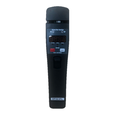
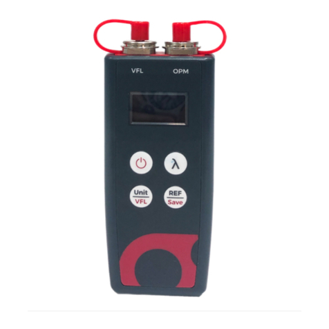
Ascentac OCI600 User manual

Copyright
© Copyright 2020 Ascentac Inc (hereinafter Ascentac). All rights reserved.
No part of this publication may be reproduced, stored in a retrieval system or
transmitted in any form or by any means, electronic, mechanical, photocopying,
recording or otherwise, without prior permission of Ascentac.
Disclaimer
Ascentac shall not be liable for errors contained herein or for incidental or
consequential damages in connection with the furnishing, performance, or use of
this user guide.
The material in this document is subject to change without notice. For the latest
information regarding this product, please visit our website at
http://www.ascentac.com.
All other trademarks and registered trademarks which appear herein are for
reference purposes only and are the property of their respective owners.

Warranty
Ascentac warrants the product against defects in material and workmanship within
(1) year from the date of delivery. Under normal use and service, the product will
be free from physical defects in material and workmanship during the warranty
period, or the product will be repaired or replaced as determined solely by
Ascentac.
During the warranty period, you and Ascentac will pay the shipping costs for
repairing products for one time respectively. Products returned without proof of
purchase or with expired warranty will be repaired or replaced by Ascentac’s
decision. You shall pay the charges, including maintenance cost, shipping,
insurance, duties, taxes, import fees or others which may be caused.
This warranty provides you with specific legal rights. You may have additional rights
which may vary from state to state and country to country. Because of individual
state and country regulations, some of the above limitations and exclusions may
not apply to you.
If any of the following conditions takes place, the warranty shall be null and void.
Defects or malfunction caused by human factors, accident, improper use not
conforming to product manual instructions, abuse or unauthorized alteration,
modification or repair of the product.
The label with S/N has been altered or damaged.
Notice: Ascentac makes no warranty of any kind with regard to the content in this
document, including, but not limited to, the implied warranties of merchantability
and fitness for a particular purpose.

Service & Support
If you have any questions or need any assistance, please contact our service
center.
Kaohsiung Office
TEL: +886-7-398-1000
FAX: +886-7-398-3965
Address: 11F.-1, No.80, Minzu 1st Rd., Sanmin Dist., Kaohsiung City 80761, Taiwan
(R.O.C.)
Please prepare below information before you contact us and describe the
problems.
Product model and S/N
Warranty information

i
Content
1. Safety Information .....................................................................................................................1
2. Introduction ................................................................................................................................2
2.1 Features .............................................................................................................................3
2.2 Application........................................................................................................................3
3. Layout .........................................................................................................................................4
3.1 Appearance .....................................................................................................................4
3.2 Instruction ..........................................................................................................................5
3.3 LED Indicator .....................................................................................................................5
4. Display.........................................................................................................................................6
5. Operation ...................................................................................................................................8
5.1 Power-on............................................................................................................................8
5.2 Home Screen ....................................................................................................................8
5.3 Optical Cable Identifier...................................................................................................9
5.3.1 Automatic Detection.........................................................................................10
5.3.2 Test........................................................................................................................11
5.3.3 ECG ......................................................................................................................13
5.3.4 Stop Test...............................................................................................................14
5.3.5 Setting Volume....................................................................................................15
5.3.6 Setting Sensitivity.................................................................................................16
5.3.7 Setting Noise Cancellation................................................................................18
5.4 Visual Fault Locator ........................................................................................................20
5.4.1 Mode....................................................................................................................21
5.4.2 Laser-on & Laser-off............................................................................................21

ii
5.4.3 Exit.........................................................................................................................22
5.5 Power Meter....................................................................................................................22
5.5.1 Measurement......................................................................................................24
5.5.2 Wavelength.........................................................................................................25
5.5.3 Reference Value ................................................................................................26
5.5.4 Measuring Unit ....................................................................................................27
5.5.5 MAX. & MIN. ........................................................................................................28
5.5.6 Threshold..............................................................................................................29
5.5.7 Save......................................................................................................................31
5.6 Loss Meter ........................................................................................................................33
5.6.1 Measurement......................................................................................................34
5.6.2 Zero.......................................................................................................................35
5.6.3 Exit.........................................................................................................................35
5.7 Light Source.....................................................................................................................36
5.7.1 Mode....................................................................................................................37
5.7.2 Laser-on & Laser-off............................................................................................37
5.7.3 Exit.........................................................................................................................38
5.8 Setting ..............................................................................................................................38
5.8.1 Setup......................................................................................................................................39
5.8.1.1 Date .......................................................................................................................................40
5.8.1.2 Time ........................................................................................................................................41
5.8.1.3 Sleep Mode ..........................................................................................................................41
5.8.1.4 Backlight Auto-off................................................................................................................42
5.8.1.5 Display Brightness ................................................................................................................42
5.8.1.6 Network Information ...........................................................................................................43
5.8.1.7 Language .............................................................................................................................44

iii
5.8.1.8 Storage Device ....................................................................................................................44
5.8.2 About ...................................................................................................................45
5.8.3 Exit.........................................................................................................................45
5.9 File Management ...........................................................................................................46
5.9.1 Report...................................................................................................................47
5.9.2 Delete...................................................................................................................48
5.9.3 Exit.........................................................................................................................48

1|OCI600
1. Safety Information
Read all safety information carefully before using this product to ensure personal
safety and proper use.
Assure the power supply conforming to the specification of this product and
qualified for the country of use.
Use batteries that meet the specifications of this product.
Do not use damaged power cords, accessories or other peripheral
equipment.
Make sure the product is operated on the permitted ambient conditions.
Never directly look into the optical outputs interface.
Dangerous laser radiation:

2|OCI600
2. Introduction
Ascentac OCI 600 Series, Optical Cable Identifier is specially designed for fast,
accurate and nondestructive identification of target optical cables. The
identifier applies the principle of light interference to transform mechanical
vibration to visual or audio signals. Technicians only need to lightly hit cables.
With its high sensitivity and noise reduction, the identifier can lower noises to
make technicians clearly hear the knocking sound by earphones. For visual
signal, the strength is classified into ten grades with three colors, involving red,
yellow and green. Technicians can easily recognize whether it is the target
cable through the colors
Ascentac OCI 600 Series is easy to operate by its one-touch automatic testing
and available to various environments because of its strong on-spot application
capacity. The powerful functions not only greatly reduce the time, cost and
errors of urgently repairing optical cables for technicians but also significantly
improves the work efficiency.

3|OCI600
2.1 Features
Present whether the target cable has been hit in bar graph or ECG
(Electrocardiography)
Dual identification methods (By visual or audio)
Strong environmental adaptability e.g. manholes, tunnels, conduits,
aerial etc.
Noise suppression
Adjustable receiver sensitivity
2.2 Application
Optical cable construction, installation & maintenance
1. Pinpoint unlabelled patch cords in the equipment room
2. Identify far-end cables under different environment like manholes,
tunnels, conduits or elevated construction
3. Fiber cut, splicing, resource inventory

4|OCI600
3. Layout
3.1 Appearance
Front
Top
Back

5|OCI600
3.2 Instruction
Button
Function
Item
Function
Power on/off
1
Power
Start or stop
2
Ethernet
: Enter
3
Optical Cable Identifier
/ Optical Light Source
: Up / Down
4
Optical Power Meter
: Left / Right
5
Visual Fault Locator
Menu or ESC
A
Battery
F1 to F4
Function keys
B
Support stand
3.3 LED Indicator
Icon
LED Indicator
LED Status
Description
Laser
Off
Laser Off
Red
Laser On
Battery
Red
Low battery
Orange
Charging
Green
Normal

6|OCI600
4. Display

7|OCI600
Icon
Function
Description
Optical Cable
Identifier
Identify the target cable
Visual Fault Locator
Troubleshooting: Red
illumination indicating fiber
damages, bends or breaks
Power Meter
Optical power
measurement
Loss Meter
Measuring the loss of fiber
optic line or passive
components
Light Source
Outputting stable light
Setting
Device settings
File Management
Record of saved optical
power value
Icon
Function
Description
Battery
status
Fully charged
Low battery
Insufficient power
Charging
Brightness
The brightness of LCD display can be adjusted.
Alert
tone
On
Off

8|OCI600
5. Operation
5.1 Power-on
Long Press [ ] key for two seconds to turn on the equipment and enter
into startup screen.
5.2 Home Screen
Short press [ ], [ ], [ ] or [ ] key to move to the desired
function, and then short press [ ] key to enter into the home screen of
the function or directly tap the function icon on the screen to enter into it.

9|OCI600
5.3 Optical Cable Identifier
Short press [ ], [ ], [ ] or [ ] key to move to OCI, and
then short press [ ] key to enter into the home screen of optical cable
identifier or directly tap [ ] on the screen to enter into it.

10 |OCI600
5.3.1 Automatic Detection
Short press [ ] key or directly tap [ Start ] on the screen to start
the detection. The identifier will automatically adjust the parameters,
detect the cable, and reduce background noise. The pop-up
window will show up during the adjustment and disappear after
adjustment is done.
Note
1. To increase the accuracy of detection, please don’t hit the
optical cable during detecting
2. Please restart the automatic detection to ensure the best
performance whenever you change the optical cable.

11 |OCI600
5.3.2 Test
The test of identifying the target optical cable will be conduct
after the automatic detection is done.
The color indicator will have corresponding reaction according
to the hitting strength.
will appear on the display and LED indicator will be red when
the laser is turned on.
Color indicator:
Red: The strength of signal is weak. Not the target one.
Yellow: The strength of signal is medium. The target cable or
the cable next to it has been hit. Change the hit point or
strengthen the hit.
Green: The strength of signal is high. The target cable has
been hit.

12 |OCI600
Note
1. The hit point should be away from the fixed point of cable bundle
to avoid the hitting strength which could possible transfer from
one to another. The distance from hit point to fixed point of cable
bundle should be over 1 meter.
2. The color indicator will show RED when things as below
happened.
Optical cable return loss or total return loss is massive.
The reflected amount of remote joint face is low.
The value of sensitivity set manually is too low.

13 |OCI600
5.3.3 ECG
Short press [ F2 ] key or directly tap [ ECG ] on the screen to present
whether the target cable has been hit in ECG (Electrocardiography).
Short press [ F1 ] key or directly tap [ Bar ] on the screen to be back
to present whether the target cable has been hit in bar.
Table of contents
Other Ascentac Measuring Instrument manuals