ASCOM BS330 User manual

Installation instructions, BS330 base station
Technical Product Manual - DCT1800-GAP
TD 92093 (1/LZBNB 103 108 R4D) / 2005-09-23/ Ver.C
2005
63
Chapter 16 BS330 base station
16.1 General
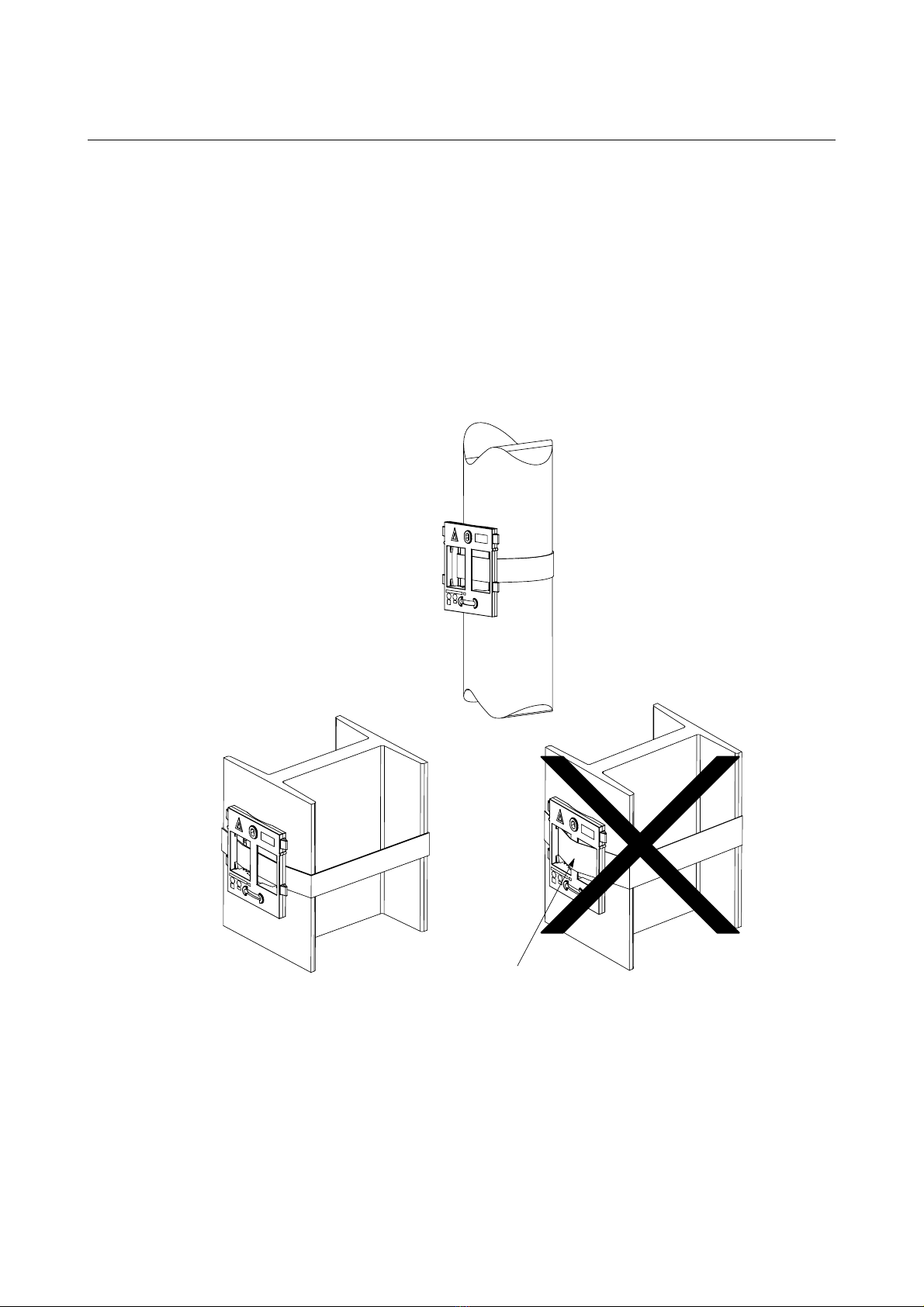
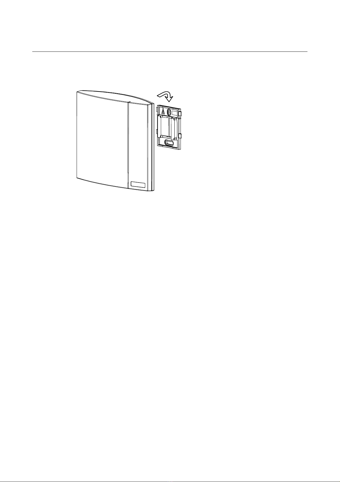
The base station is connected to the radio exchange by means of a standard twisted pair cable. The base station
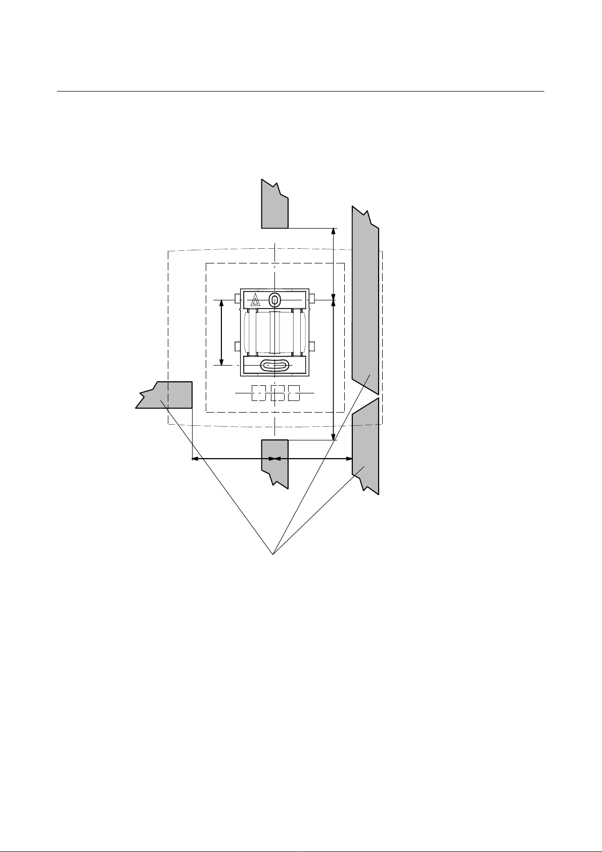
is can be fixed to a wall, a ceiling, a pole or a beam, by means of the mounting bracket included. When fixing
the base station to a wall or ceiling the included plugs and screws must be used. When fixing it to a pole or beam
a (not included) strap a flexible metal band must be used.
Versions
The following versions of the BS330 are available:
• BS330/STD: 1880 – 1900 MHz
• BS330/CHINA: 1900 – 1920 MHz
• BS330/LA: 1910 – 1930 MHz
• BS330/US&CDA: 1920 – 1930 MHz
Contents of the box
The box in which the base station is packed contains:
• A base station
• A mounting bracket
• Two screws with wall plugs
Note:
The brand label is not included in the box, but must be ordered separately.
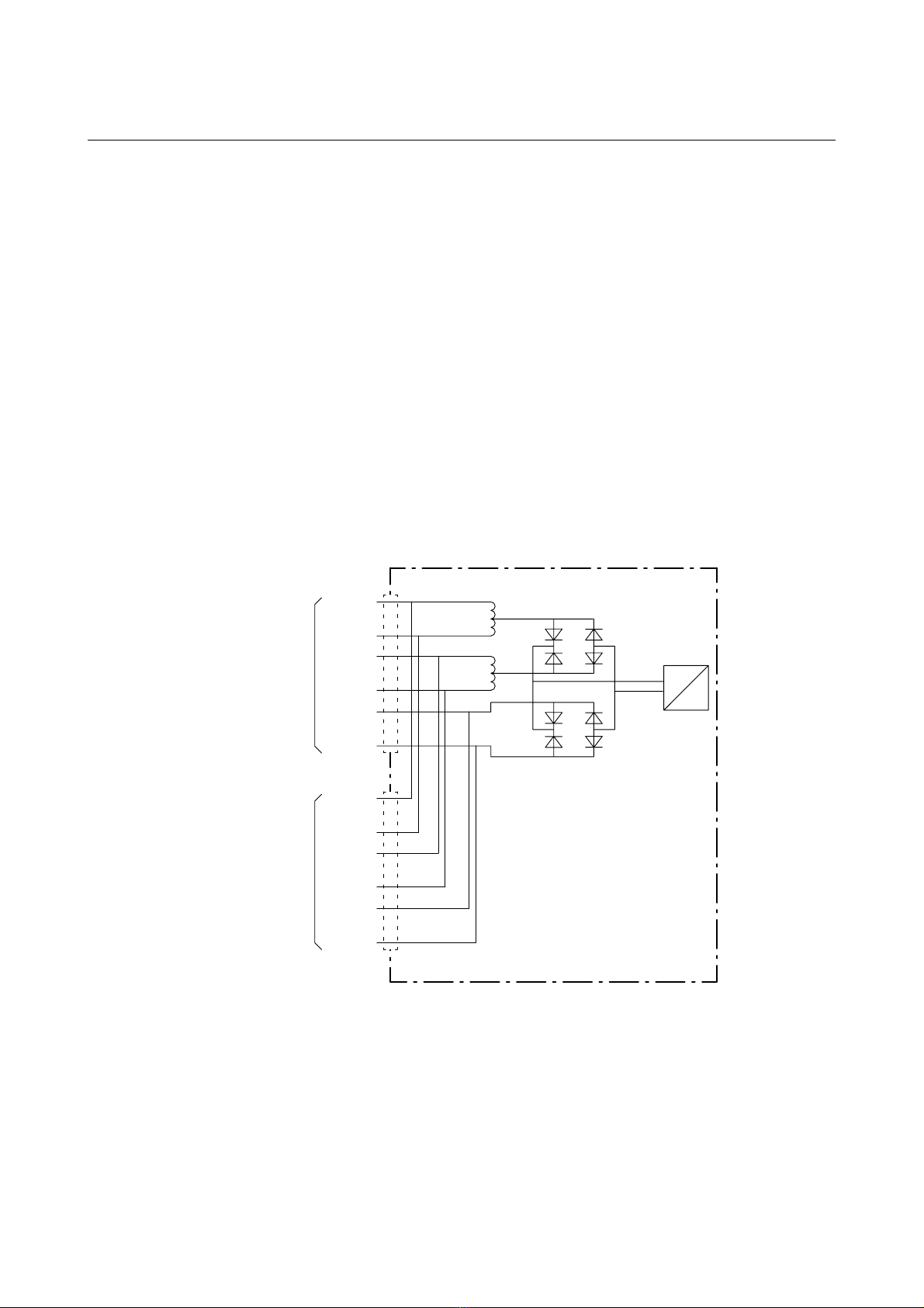
Power distribution
Base stations can be powered by the following sources:
• The radio exchange via the data pairs
• The radio exchange via the data and Express Powering Pairs (EPP)
• A 48 V external supply connected to the radio exchange
• A local AC-adapter
Note:
For more information about power distribution, refer to the section ‘Configuration directions’.
AC-adapter for a base station
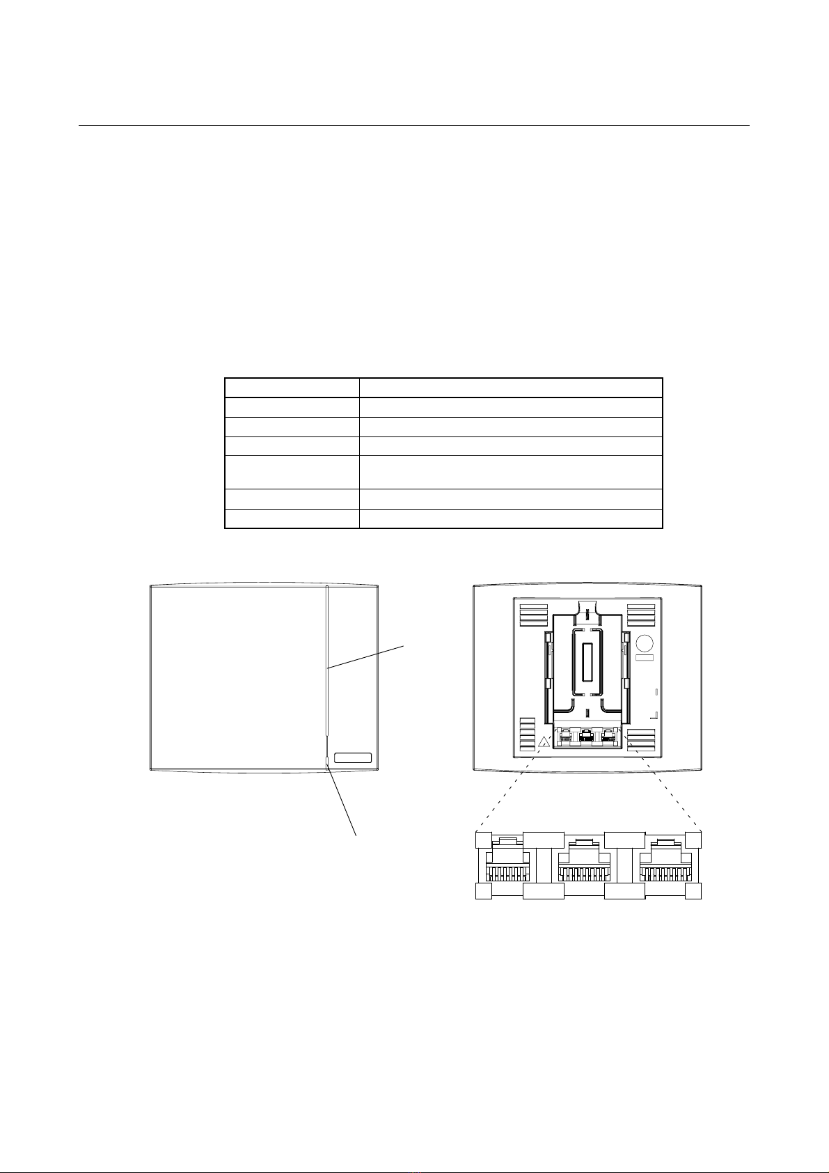
A 24 Vdc adapter (BMLNB 101 09/n) can be used. This adapter is provided with an 8-pin RJ45 plug that can
be plugged into one of the data/power connectors of the base station.
Software
If necessary, the software in the base station can be updated by downloading new software to the base station.
Downloading can be performed without disconnecting the base stations. The new software is stored in flash
memory. How to download the software is described in the help file of the application Cordless System Manager
(CSM) for Windows.

Installation instructions, BS330 base station
Technical Product Manual - DCT1800-GAP
TD 92093 (1/LZBNB 103 108 R4D) / 2005-09-23/ Ver.C
2005
64
Connectors
• Two 8-pin RJ45 modular jacks for data and powering
• A 6-pin RJ12 modular jack for factory testing
The two data/powering connectors are interconnected on the board.
LEDs
LED 1 : Green power LED
LED 2 : Three colour LED, see table 1
Fig. 35 BS330 base station
Status of LED2 Meaning
Off Base station operational and no traffic on the base station
Green Base station operational and traffic on the base station
Red Base station is malfunctioning
Amber Base station is OK, but not available (self-test, not initialized, no
communication with radio exchange)
Flashing green All 8 channels are in use
Flashing amber Software is being downloaded to the base station
Table 1 Meaning of LED2
Factory
testing
(RJ12) Data/
power
(RJ45)
Data/
power
(RJ45)
Front view Back view
LED1
LED2
037

Installation instructions, BS330 base station
Technical Product Manual - DCT1800-GAP
TD 92093 (1/LZBNB 103 108 R4D) / 2005-09-23/ Ver.C
2005
65
16.2 Base station cabling
The base station cable must be a twisted pair cable with 2 pairs minimum for connection of the data lines. Also
power can be distributed via these data pairs.
A three-pair cable may be used when additional power wires (EPP) are required to increase the distance between
base station and radio exchange. If more EPP wires are necessary they can be connected to the EPP pins of the
second data/power connector, or they can be connected to one connector when using a screw-to-RJ45 adapter.
Data lines of the same twisted pair may be interchanged. For instance SC0-a and SC0-b (see figure 40) may be
interchanged. Also the EPP pair is insensitive for polarity reversal. Data pairs may not be interchanged.
It is assumed that service personnel know how to crimp these connectors to a cable.
Do not power the base station via the EPP terminals from a local power source and the radio exchange
simultaneously. As the two EPP inputs of the base station are interconnected in the base station, the two power
sources would be interconnected (see figure 36). However, the base station can be powered via the data pairs
from the radio exchange and the local power source simultaneously because they are interconnected via a
rectifier.
Fig. 36 Base station powering
16.3 Installation
Base stations can be mounted vertically or horizontally. Mount the base stations at places and positions as
determined in the system configuration plan. The base station must be placed such that it is not facing large
metal objects such as large heating pipes.
SC0-b
SC1-b
SC0-a
SC1-a
EPP-b
EPP-a
SC0-b
SC1-b
SC0-a
SC1-a
EPP-b
EPP-a
D
ata/power
connector 1
D
ata/power connector 2
+
−
DCDC
Base station
038

Installation instructions, BS330 base station
Technical Product Manual - DCT1800-GAP
TD 92093 (1/LZBNB 103 108 R4D) / 2005-09-23/ Ver.C
2005
66
16.3.1 Fixing the mounting bracket to a wall
Fix the mounting bracket (see figure 37) to the wall as follows:
1. Hold the mounting bracket with its flat side against the wall such that the text ‘TOP’ is the right way up,
and mark the two holes. The minimum distance between the upper hole and the ceiling or any object above
the base station must be at least 65 mm (see figure 37). If the distance is less than 65 mm, the base station
cannot be slid onto the bracket.
2. When using wall plugs, take a ∅6 mm drill and drill the two holes and insert the included wall plugs.
3. Position the mounting bracket with its flat side to the wall and fasten it with the two included ∅3.5 mm
screws.
Fig. 37 Fixing the mounting bracket to a wall
TOP
≥ 65 mm
C
eiling
039

Installation instructions, BS330 base station
Technical Product Manual - DCT1800-GAP
TD 92093 (1/LZBNB 103 108 R4D) / 2005-09-23/ Ver.C
2005
67
16.3.2 Fixing the mounting bracket to a ceiling
Fixing to a ceiling is done in the same way as the a wall (see paragraph 16.3.1). When the base station has to
be positioned above a suspended ceiling, take care that the front of the base station points downwards.
16.3.3 Fixing the mounting bracket to a pole or beam
The mounting bracket can be fixed to a pole (diameter ≥45 mm) or a beam (wider than 50 mm) by means of a
strap or flexible metal band less than 30 mm wide. The strap or flexible metal band must be purchased locally.
1. Fix the mounting bracket to a pole or beam such that the text ‘TOP’ is right way up (see figure 38).
Fig. 38 Fixing the mounting bracket to a pole or beam
16.3.4 Using cable ducts
When the base station is mounted to the wall, cable ducts can be used to route the wiring through.
Tied
wrongly
040

Installation instructions, BS330 base station
Technical Product Manual - DCT1800-GAP
TD 92093 (1/LZBNB 103 108 R4D) / 2005-09-23/ Ver.C
2005
68
1. Fix the cable duct to the wall in one of the positions shown in figure 39.
Fig. 39 Minimum distances between a cable duct and the mounting bracket
16.3.5 Securing the base station cable
1. For safety reasons secure the base station cable to a convenient point at about 30 cm from the base station.
If for some reason the base station drops, the cable is pulled out of the base station.
16.3.6 Connecting the base station plug to the cable
1. Cut the base station cable to the correct length and connect the cable to a RJ45 modular jack (see figure
40). Do not plug the connector in the base station yet!
Note:
The power inlet of the base station (EPP) is insensitive of polarity reversals
TOP
65
mm
125 mm
70 mm75 mm
57 mm
15 mm thick cable ducts
041

Installation instructions, BS330 base station
Technical Product Manual - DCT1800-GAP
TD 92093 (1/LZBNB 103 108 R4D) / 2005-09-23/ Ver.C
2005
69
Fig. 40 Connector pinning of the data/power connector
16.3.7 Base station cable delay measurement
Note:
The cable delay measurement is only necessary when the base station is connected to a CLU
REX-BRD0014 (ROFNB 157 11/2), or to an SLU board REX-BRD0015 or REX-BRD0026 with a revision lower
than R2A.
After all base stations have been installed, the cable delays must be measured in order to program the base
station delays into the system at initialization time.
Base station delays are measured at the radio exchange with an echo-meter connected to cable data pair SC0 or
SC1 and with the cable open ended at both sides. So the cable must be disconnected from the CLU, CLU-S or
SLU as well as the base station.
1. Make sure that the base station cable is unplugged from the base station.
2. Disconnect relevant connector from the relevant CLU, CLU-S or SLU.
3. Connect an echo-meter to cable pair SC0 or SC1.
4. Measure the cable delay. The measured delay is the time between sending a pulse down the line and receiving
the echo. Therefore the recorded value is twice the cable delay and must be halved. The resulting value
must have an accuracy of 200 ns (corresponding with 20 – 30 m).
5. Record on paper the delay value measured for each base station in microseconds, together with the base
station number.
6. Repeat the delay measurement for all base stations connected to the CLU, CLU-S or SLU.
7. Re-connect the connectors to the CLU, CLU-S or SLU.
If applicable repeat the delay measurement for the base stations connected to the other CLUs and SLUs.
16.3.8 Sticking the label on the base station
Brand labels have to be ordered separately.
R
J45
m
odular jack
EPP-b
EPP-a
SC1-a
SC0-a
SC0-b
SC1-b
NC
NC
NC
=
Not connected
EPP
=
Express Power Pa
ir
SC =Serial Channel
0
42

Installation instructions, BS330 base station
Technical Product Manual - DCT1800-GAP
TD 92093 (1/LZBNB 103 108 R4D) / 2005-09-23/ Ver.C
2005
70
1. Stick the brand label in the front cover recess.
16.3.9 Connecting the base station cables
1. If it is required that the cables enter the base station centrally from above, guide the cables through the
recess in the middle of the base station as shown in figure 41.
Fig. 41 Cables entering the base station centrally from above
2. Plug the modular jack of the data cable into one of the data/power connectors.
3. When an AC-adapter is used:
– Plug the modular jack of the AC-adapter in one of the data/power connectors.
– Plug the AC-adapter into a wall-outlet.
Note:
See also chapter 22, ‘CLU/CLU-S/SLU to base station cabling’
16.3.10 Mounting the base station
1. Hold the base station flat against the mounting bracket and move it downwards until it clicks (see figure 42).
Note:
After completion of the installation, base stations must be initialized using the cordless system manager.
Power
cable
(if used)
Data cable
043

Installation instructions, BS330 base station
Technical Product Manual - DCT1800-GAP
TD 92093 (1/LZBNB 103 108 R4D) / 2005-09-23/ Ver.C
2005
71
Fig. 42 Mounting the base station
044

Installation instructions, BS330 base station
Technical Product Manual - DCT1800-GAP
TD 92093 (1/LZBNB 103 108 R4D) / 2005-09-23/ Ver.C
2005
72
Table of contents
Other ASCOM Accessories manuals