ASCOM IP-DECT IPBS1 User manual

TD 92989EN
15 October 2014 / Ver. B
Installation Guide
IP-DECT Base Station and IP-DECT Gateway

TD 92989EN
15 October 2014 / Ver. B
Installation Guide
IP-DECT Base Station & IP-DECT Gateway
Contents
1 Introduction............................................................................................................. 1
1.1 Abbreviations and Glossary ................................................................................ 1
2 Description............................................................................................................... 2
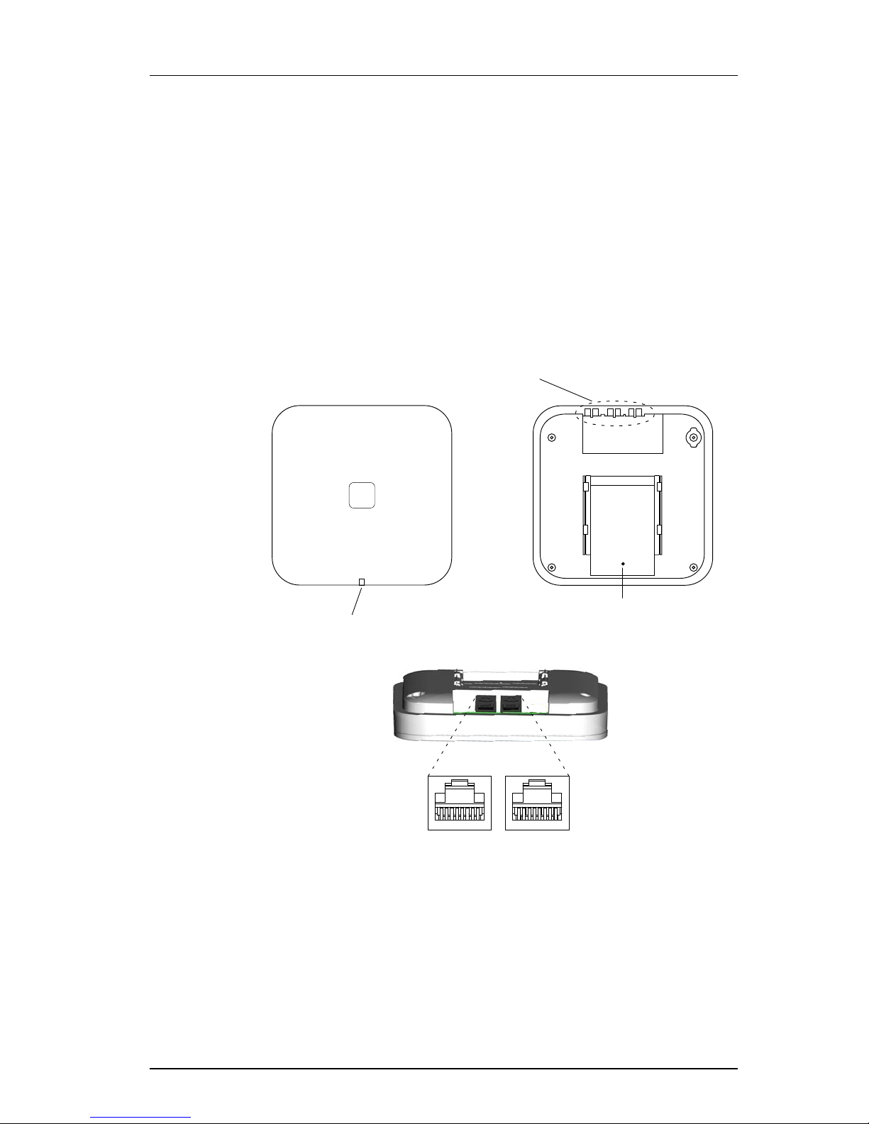
2.1 IPBS1 ................................................................................................................. 2
2.1.1 IPBS1 with Internal Antenna ...................................................................... 2
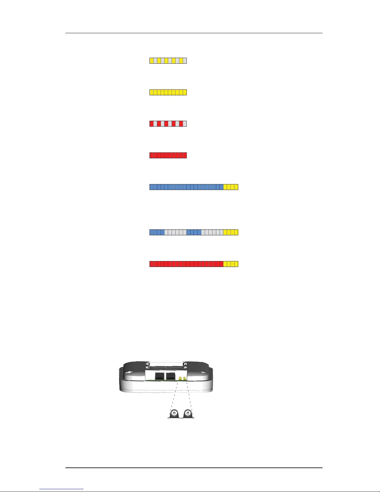
2.1.2 IPBS1 with External Antennas .................................................................... 4
2.2 IPBS2 ................................................................................................................. 5
2.2.1 IPBS2 with Internal Antenna ...................................................................... 5
2.2.2 IPBS2 with External Antennas .................................................................... 7
2.3 IPBL ................................................................................................................... 9
2.3.1 Overview ................................................................................................... 9
2.3.2 Power Supply ............................................................................................. 9
2.3.3 LED indication .......................................................................................... 10
2.4 BS3x0 .............................................................................................................. 12
2.5 DB1 ................................................................................................................. 14
2.5.1 DB1 with Internal Antenna ...................................................................... 14
2.5.2 DB1 with External Antennas .................................................................... 16
2.6 AC-adapter ...................................................................................................... 17
3 Installation of the Base Station............................................................................ 18
3.1 Base Station Cabling ........................................................................................ 18
3.2 Install the Base Station ..................................................................................... 18
3.2.1 Fix the Mounting Bracket to a Wall .......................................................... 18
3.2.2 Fix the Mounting Bracket to a Ceiling ...................................................... 19
3.2.3 Fix the Mounting Bracket to a Pole or Beam ............................................. 19
3.2.4 Use the Cable Ducts for IPBS1 .................................................................. 20
3.2.5 Connect External Antennas (only IPBS2 and DB1) ..................................... 21
3.2.6 Secure the Cable ...................................................................................... 23
3.2.7 Pinning .................................................................................................... 23
3.2.8 Connect the Base Station Cables .............................................................. 24
3.2.9 Mount the Base Station ........................................................................... 24
3.3 Power the Base Station .................................................................................... 25
3.3.1 Power the IPBS over Ethernet ................................................................... 25
3.3.2 Power the BS3x0 and DB1 over Express Powering Pair (EPP) and data pairs 25
3.3.3 Power the Base Station with a Local Power Supply ................................... 25
4 Installation of the IPBL.......................................................................................... 27
4.1 Install the IPBL .................................................................................................. 27
4.2 Pin the IPBL Cable ............................................................................................ 29
4.2.1 Synchronization Cable ............................................................................. 29

TD 92989EN
15 October 2014 / Ver. B
Installation Guide
IP-DECT Base Station & IP-DECT Gateway
4.2.2 RFP Cable ................................................................................................ 30
4.2.3 LAN Cable ............................................................................................... 30
4.3 Power the IPBL ................................................................................................. 31
4.3.1 110/230 VAC ........................................................................................... 31
4.3.2 48 VDC ................................................................................................... 32
5 Related Documents ............................................................................................... 33
Appendix A. RFP Power Consumption ................................................................... 35

TD 92989EN
15 October 2014 / Ver. B
Installation Guide
IP-DECT Base Station & IP-DECT Gateway
1
1 Introduction
This document describes how to install the following device:
•IPBS
1
•IPBL
2
The document is intended for service technicians.
For information on how to operate the device, see the applicable Installation and
Operation Manual for the device.
For information about supported PBXs contact your supplier.
1.1 Abbreviations and Glossary
Base Station Common name for IPBS, DECT Base Station (BS3x0) and TDM-DECT Base
Station.
DECT Digital Enhanced Cordless Telecommunications:
global standard for cordless telecommunication.
DECT Base
Station
Another name for BS3x0
TDM-DECT
Base Station
Another name for DB1.
GUI Graphical User Interface
IP Internet Protocol:
global standard that defines how to send data from one computer to
another through the Internet
IPBL Previously called IP-DECT Gateway or, more commonly, as "the Blade"
IPBS Also referred to as IPBS Base Station. Previously called IP-DECT Base Station
LAN Local Area Network:
a group of computers and associated devices that share a common
communication line.
PBX Private Branch Exchange:
telephone system within an enterprise that switches calls between local lines
and allows all users to share a certain number of external lines.
RFP Radio Fixed Part. DECT base Station part of the DECT Infrastructure.
RSTP Rapid Spanning Tree Protocol
1.In previous documentation, IPBS Base Station (or IPBS) was sometimes referred to as IP-DECT Base Station.
2.IIn previous documentation, IPBL was sometimes referred to as IP-DECT Gateway.

TD 92989EN
15 October 2014 / Ver. B
Installation Guide
IP-DECT Base Station & IP-DECT Gateway
2
2 Description
This section gives a general description of the following devices:
• IPBS1, see 2.1 IPBS1
• IPBS2, see 2.2 IPBS2 on page 5
• IPBL, see 2.3 IPBL on page 9
• BS3x0, see 2.4 BS3x0 on page 12.
• DB1, see 2.5 DB1 on page 14
2.1 IPBS1
The following versions of the IPBS1 are available:
• IPBS1 with internal antenna
• IPBS1 with external antennas
2.1.1 IPBS1 with Internal Antenna
Figure 1. IPBS1 Overview
Contents of the Box
The box in which the IPBS1 is packed contains:
• An IPBS1 with integrated antennas
• A mounting bracket
• Two screws with wall plugs
Test
(RJ12)
LAN
(RJ45)
Power Supply
(RJ45)
Front view Back view
LED1
LED2
005
Reset

TD 92989EN
15 October 2014 / Ver. B
Installation Guide
IP-DECT Base Station & IP-DECT Gateway
3
Power Distribution
The IPBS1 can be powered using the following methods:
• Power over Ethernet, IEEE 802.3af
• A local AC-adapter
NOTE: For more information about power distribution, see 3.3 Power the Base Station on
page 25.
Software
The software in the IPBS1 can be updated by downloading new software without
disconnecting the equipment. The new software is stored in flash memory. For
information on how to update the software in the IPBS1, see the applicable Installation
and Operation Manual for the IPBS1.
Connectors
• Two 8-pin RJ45 modular jacks for LAN/PoE and powering
• A 6-pin RJ12 modular jack for factory testing
LEDs
Status of LED1 (lower LED) Description
Steady Green Operational
Flashing fast amber Download of firmware in progress.
Steady Amber TFTP mode
Alternating red/green No Ethernet connection
Status of LED2 (upper LED) Description
Not lit IPBS1 operational and no traffic on the IPBS1.
Steady green IPBS1 operational and traffic on the IPBS1.
Flashing slow green Fully occupied with traffic.
Flashing red No air synchronization - searching for air sync
candidates.
Flashing fast red Download of RFP software in progress.
Alternating red/green RFP not initialized.

TD 92989EN
15 October 2014 / Ver. B
Installation Guide
IP-DECT Base Station & IP-DECT Gateway
4
2.1.2 IPBS1 with External Antennas
The IPBS1 is available with two omni-directional external antennas. Other external
antennas can be mounted as well. This section contains the differences between the IPBS1
with internal and external antennas. For all other information see 2.1.1 IPBS1 with Internal
Antenna on page 2.
Contents of the Box
The box in which the IPBS1 is packed contains:
• An IPBS1 for external antennas
• Two antennas
• A mounting bracket
• Two screws with wall plugs
NOTE: The IPBS1 cannot be mounted with the antennas pointing downwards as the
mounting bracket does not support it.
Insert the antennas into the IPBS1 before following the installation instructions in
3.2 Install the Base Station on page 18.

TD 92989EN
15 October 2014 / Ver. B
Installation Guide
IP-DECT Base Station & IP-DECT Gateway
5
2.2 IPBS2
The following versions of the IPBS2 are available:
• IPBS2 with internal antenna
• IPBS2 with external antennas
The IPBS2 is backward compatible with the IPBS1 when it comes to coverage,
functionality, accessories and mounting bracket. If an old IPBS1 has to be replaced you just
reuse the mounting bracket and install the IPBS2.
2.2.1 IPBS2 with Internal Antenna
Figure 2. IPBS2 Overview
Contents of the Box
The box in which the IPBS2 is packed contains:
• An IPBS2 with integrated antennas
• A mounting bracket
• Two screws with wall plugs
Front view
LED
LAN
(RJ45)
Power Supply
(RJ45)
Back view while lying down
Used for cable ties
to provide strain
relief for cables
Back view
Reset

TD 92989EN
15 October 2014 / Ver. B
Installation Guide
IP-DECT Base Station & IP-DECT Gateway
6
Power Distribution
The IPBS2 can be powered using the following methods:
• Power over Ethernet, IEEE 802.3af
• A local AC-adapter
NOTE: For more information about power distribution, see 3.3 Power the Base Station on
page 25.
Software
The software in the IPBS2 can be updated by downloading new software without
disconnecting the equipment. The new software is stored in flash memory. For
information on how to update the software in the IPBS2, see the applicable Installation
and Operation Manual for the IPBS2.
Connectors
• Two 8-pin RJ45 modular jacks for LAN/PoE and powering
LEDs
The IPBS2 has one RGB LED to indicate status. This section describes the different
indications and when they shall be used. In the illustrations below: Each blink pattern is
represented by a number of blocks where each block is 100 ms. Light grey blocks means
that the LED is off. Whenever the indication is changed the new pattern always starts from
the first block.
Idle/OK Solid blue. IPBS2 operational and no
traffic on the IPBS2.
Starting up/
searching
100 ms blue, 100 ms off. The IPBS2 is in start-up
phase, e.g. waiting for
parameters from PARI
Master, or is searching for air
synchronization, or the radio
is disabled.
Active traffic 400 ms off, 2000 ms blue. IPBS2 operational and traffic
on the IPBS2.
Fully occupied for
speech traffic
400 ms red, 2000 ms blue. Fully occupied with traffic.
Software
download
400 ms blue, 600 ms off. Download of firmware in
progress.

TD 92989EN
15 October 2014 / Ver. B
Installation Guide
IP-DECT Base Station & IP-DECT Gateway
7
2.2.2 IPBS2 with External Antennas
This section contains the differences between the IPBS2 with internal antenna and the
IPBS2 with external antennas. For all other information see 2.2.1 IPBS2 with Internal
Antenna on page 5.
Figure 3. IPBS2 with MCX connectors for external antennas.
Mini firmware 100 ms yellow, 100 ms off. The IPBS2 is in mini firmware
mode.
TFTP mode Solid yellow. TFTP mode.
Error 100 ms red, 100 ms off. No Ethernet connection.
Fatal error Solid red. Fatal hardware error.
Deployment:
Good sync
2000 ms blue, 400 ms yellow. The IPBS2 is in deployment
mode and has good air sync
coverage.
Deployment:
Bad sync
400 ms blue, 600 ms off, 400 ms blue,
600 ms off, 400 ms yellow.
The IPBS2 is in deployment
mode and does not have
adequate air sync coverage.
Deployment:
No sync
2000 ms red, 400 ms yellow. The IPBS2 is in deployment
mode and has no air sync
coverage.
Back view while lying down
MCX connectors

TD 92989EN
15 October 2014 / Ver. B
Installation Guide
IP-DECT Base Station & IP-DECT Gateway
8
Contents of the Box
The box in which the IPBS2 is packed contains:
• An IPBS2 with external antennas.
• A mounting bracket
• An antenna bracket
• Two antenna coaxial cables.
• Two antennas.
• Four screws with wall plugs

TD 92989EN
15 October 2014 / Ver. B
Installation Guide
IP-DECT Base Station & IP-DECT Gateway
9
2.3 IPBL
The following versions of the IPBL are available:
• IPBL IP-DECT Gateway VAC/VDC (for 110/230 VAC or 48 VDC)
• IPBL IP-DECT Gateway VDC (for 48 VDC)
2.3.1 Overview
Figure 4. Overview of the IPBL
2.3.2 Power Supply
The power supply are located at the rear of the IPBL. The IPBL can be powered using the
following alternatives:
• 110/230 VAC (only IPBL IP-DECT Gateway VAC/VDC)
• 48 VDC
NOTE: For more information, see 4.3 Power the IPBL on page 31.
Software
The software in the IPBL can be updated by downloading new software without
disconnecting the equipment. The new software is stored in flash memory. For
information on how to update the software in the IPBL, see the applicable Installation and
Operation Manual for the IPBL.
Pos. Name Function
1 Reset Resets the IPBL. For information on how to use the reset
button, see the applicable Installation and Operation
Manual for the IPBL.
2 Status LED Indicates the status on the IPBL.
3 Lan 10BASE-T/100BASE-T Ethernet interface.
LAN1 port must be used in the IP-DECT system (LAN2 port
is for administration only). Note: This is not applicable
when RSTP is used. For information about RSTP, see the
applicable Installation and Operation Manual for the
device.
4 Synchronization Sync ring in and sync ring out interfaces.
5 Reference Reference sync in and reference sync out interfaces.
6 Base station 01-16 ISDN UPN DECT base station interfaces.
lan synchronization reference
1 2 ring in ring out in out
base station 01 02 03 04 05 06 07 08
09 10 11 12 13 14 15 16
006
12 3 45 6

TD 92989EN
15 October 2014 / Ver. B
Installation Guide
IP-DECT Base Station & IP-DECT Gateway
10
2.3.3 LED indication
Status LED Description
Not lit Not powered, status is not defined.
Flashing slow green When pressing the reset button.
Flashing fast green Firmware update or clear config after long reset.
Steady green Status OK, system is fully operational.
Steady red Status Fail, system error condition.
Steady amber System is in TFTP server mode.
Base station LED Description
Not lit No speech activity in RFP.
Flashing All speech channels occupied in RFP.
Steady Speech activity in RFP.
Sync/Ref sync LED Description
Not lit No sync communication established.
Steady Communication established.
Sync/Ref sync LED Description
Not lit Sync port not selected as input sync source.
Flashing Sync port selected as input sync source but the
sync signal is not in sync.
Steady Sync port selected as input sync source and the
sync signal is in sync.
Lan LED Description
Not lit No link.
Flashing Link present and network activity.
Steady Link present, but no network activity.
Base station LED Description
Not lit No UPN link established.
Flashing UPN link established (activated state), RFP is not
operational.
Steady RFP is fully initialised and operational.
Lan LED Description

TD 92989EN
15 October 2014 / Ver. B
Installation Guide
IP-DECT Base Station & IP-DECT Gateway
11
Not lit 10 Mbps operation.
Steady 100 Mbps operation.

TD 92989EN
15 October 2014 / Ver. B
Installation Guide
IP-DECT Base Station & IP-DECT Gateway
12
2.4 BS3x0
The following versions are available:
• BS330 with Internal antenna
• BS340 with External antennas
Figure 5. BS3x0 Overview
Contents of the Box
The box in which the base station is packed contains:
•Abasestation
• Two antennas (only base station with external antenna)
• A mounting bracket
• Two screws with wall plugs
Power Distribution
The base station can be powered using the following methods:
• From the IPBL via the Express Powering Pair (EPP) and data pairs
• With a local AC-adapter
NOTE: For more information about power distribution, see 3.3 Power the Base Station on
page 25.
Test
(RJ12)
Data/Power
(RJ45)
Data/Power
(RJ45)
Front view Back view
LED1
LED2
007

TD 92989EN
15 October 2014 / Ver. B
Installation Guide
IP-DECT Base Station & IP-DECT Gateway
13
Software
The software in the BS3x0 can be updated by downloading new software without
disconnecting the equipment. The new software is stored in flash memory. For
information on how to update the software in the BS3x0, see the applicable Installation
and Operation Manual for the BS3x0.
Connectors
• Two 8-pin RJ45 modular jacks for data and powering
• A 6-pin RJ12 modular jack for factory testing
LEDs
Status of LED1 (lower LED) Description
Steady Green Power LED
Status of LED2 (upper LED) Description
Not lit Base station operational and no traffic on the
base station.
Flashing green Fully occupied with traffic.
Steady green Base station operational and traffic on the base
station.
Flashing amber Software is being downloaded to the base station
Steady amber Base station is OK, but not available (self-test, not
initialized, no communication with IPBL)

TD 92989EN
15 October 2014 / Ver. B
Installation Guide
IP-DECT Base Station & IP-DECT Gateway
14
2.5 DB1
The following versions of the DB1 are available:
• DB1 with internal antenna
• DB1 with external antennas
The DB1 is backward compatible with the BS3x0 when it comes to coverage, functionality,
accessories and mounting bracket. If an old BS3x0 has to be replaced you just reuse the
mounting bracket and install the DB1.
2.5.1 DB1 with Internal Antenna
Figure 6. DB1 Overview
Contents of the Box
The box in which the DB1 is packed contains:
• A DB1 with integrated antennas
• A mounting bracket
• Two screws with wall plugs
Front view
LED
DECT
(RJ45)
Power Supply
(RJ45)
Back view while lying down
Used for cable ties
to provide strain
relief for cables
Back view
DIP switch
1
ON
234

TD 92989EN
15 October 2014 / Ver. B
Installation Guide
IP-DECT Base Station & IP-DECT Gateway
15
Power Distribution
The DB1 can be powered using the following methods:
• From the IPBL via the Express Powering Pair (EPP) and data pairs
• With a local AC-adapter
NOTE: For more information about power distribution, see 3.3 Power the Base Station on
page 25.
Software
The software in the DB1 can be updated by downloading new software without
disconnecting the equipment. The new software is stored in flash memory. For
information on how to update the software in the DB1, see the applicable Installation and
Operation Manual for the DB1.
Connectors
• Two 8-pin RJ45 modular jacks for data and powering
LEDs
The DB1 has one RGB LED to indicate status. This section describes the different
indications and when they shall be used. In the illustrations below: Each blink pattern is
represented by a number of blocks where each block is 100 ms. Light grey blocks means
that the LED is off. Whenever the indication is changed the new pattern always starts from
the first block.
Idle/OK Solid blue. DB1 operational and no
traffic on the DB1.
Starting up 100 ms blue, 100 ms off. The DB1 is in start-up phase,
i.e. waiting to be initialized
by the IPBL.
Active traffic 400 ms off, 2000 ms blue. DB1 operational and traffic
on the DB1.
Fully occupied for
speech traffic
400 ms red, 2000 ms blue. Fully occupied with traffic.
Software
download
400 ms blue, 600 ms off. Download of firmware in
progress.

TD 92989EN
15 October 2014 / Ver. B
Installation Guide
IP-DECT Base Station & IP-DECT Gateway
16
DIP Switches
The DIP switches can be found on the back of the DB1, see figure 6 on page 14.
Note: DIP switch 3 and 4 shall be set to ON.
Set DIP switch 1 and 2 to ON or OFF as follows:
2.5.2 DB1 with External Antennas
This section contains the differences between the DB1 with internal antenna and the DB1
with external antennas. For all other information see 2.5.1 DB1 with Internal Antenna on
page 14.
Figure 7. DB1 with MCX connectors for external antennas.
Contents of the Box
The box in which the DB1 is packed contains:
• A DB1 with external antennas.
• A mounting bracket
• An antenna bracket
• Two antenna coaxial cables.
• Two antennas.
Error 100 ms red, 100 ms off. UPN layer 1 communication
error.
Fatal error Solid red. Fatal hardware error.
DIP switch 1: ON
DIP switch 2: ON
DB1 Standard (Europe, Africa, Middle East, Australia, New Zealand
and Asia) for use with DECT in the 1880-1900 MHz frequencies.
DIP switch 1: ON
DIP switch 2: OFF
DB1 SA (South America) for use with DECT in the 1910-1930 MHz
frequencies.
DIP switch 1: OFF
DIP switch 2: OFF
DB1 NA (North America) for use with DECT in the 1920-1930 MHz
frequencies.
Back view while lying down
MCX connectors

TD 92989EN
15 October 2014 / Ver. B
Installation Guide
IP-DECT Base Station & IP-DECT Gateway
17
• Four screws with wall plugs
2.6 AC-adapter
The AC-adapter is used to power a base station locally.
NOTE: The maximum length of cable from adapter must not exceed 10 meters.
Versions
For European countries except U.K. Art. no.: 130137B Order. no.: BSX-0013
For U.K. Art. no.: 130136B Order. no.: BSX-0014
For NA Art. no.: 130138A Order. no.: BSX-0015
For Australia Art. no.: 130139B Order. no.: 660263
(different type of mains plug)
IMPORTANT: If local power supply is used for the RFPs, the EPP cable pair must NOT be
connected.
This manual suits for next models
4
Table of contents
Other ASCOM Accessories manuals
Popular Accessories manuals by other brands

Best
Best L2936 Specification sheet

Perenio
Perenio PECLS01 Installation and operation manual

Taurus
Taurus COMFORT THERM CPH-20 manual

Zehnder Rittling
Zehnder Rittling ComfoAir 70 Installation notes

Ace
Ace Hardwired Mechanical Chime 598-1223-01 owner's manual

Coveya
Coveya EASYVEYOR Operation and maintenance manual

DARCHE
DARCHE KOZI Series instruction manual

AMC
AMC 1022 D instructions

Medisan
Medisan UV SANITIZING TOOTHBRUSH HOLDER manual

ORION TELESCOPES & BINOCULARS
ORION TELESCOPES & BINOCULARS SSSSI-III instruction manual

Tait
Tait TB9100 Installation and operation manual

Tektronix
Tektronix Trimode TDP7700 Series user manual