ASCOM Elise3 Lite User manual

Installation Guide
Elise3
TD 92679EN
22 November 2013 / Ver. G

TD 92679EN
22 November 2013 / Ver. G
Installation Guide
Elise3
Copyright © 2013 Ascom (US) Inc.
© 2013 Ascom (Sweden) AB
This document may not be copied in whole or in part or
otherwise reproduced without prior written consent from
Ascom, except where specifically permitted under US and
international copyright law.
Disclaimer The information in this document is subject to change.
Use this product only in accordance with the instructions
provided in the installation and user guide manuals. Use
this product only in accordance with the purposes for
which it is designed. For the latest version of all Ascom
documentation, contact your local supplier or visit the
Ascom Partner Website at
https://www.ascom-ws.com
HIPAA disclaimer All examples of personal or protected health information
in this document are fictitious. Any resemblance to a real
person or facility is purely coincidental. The owners and
users of this product are solely responsible for complying
with all applicable protected health information privacy
laws. The users, by their use of this product, agree to
indemnify the manufacturer or seller of this product
against all claims, litigation, and suits filed for protected
health information violations.
Trademarks and patents The teleCARE name and logo are trademarks of Ascom.
Other trade names used in this document may be
trademarks or registered trademarks of the
manufacturers or vendors of the respective products.
This publication may contain examples of screen captures
and reports used in daily operations. Examples may
include fictitious names of individuals and companies.
Any similarity to names and addresses of actual
businesses or persons is entirely coincidental.
European Union directives The European directive "Waste Electrical and Electronic
Equipment" (WEEE) aims to minimize the impact of
electrical and electronic equipment waste on the
environment and human health. To conform to this
directive, electrical equipment marked with this symbol
must not be disposed of in European public disposal
systems. European users of electrical equipment must
now return end-of-life equipment for disposal. Further
information may be found on the following website:
www.recyclethis.info

TD 92679EN
22 November 2013 / Ver. G
Installation Guide
Elise3
Regulatory Compliance
(EU/EFTA)
This equipment is intended to be used in the whole EU &
EFTA.
This equipment is in compliance with the essential
requirements and other relevant provisions of EMC
Directive 2004/1 08/EC, LVD Directive 2006/95/EC, Eco
Design 2005/32/EC, and RoHS Directive 2011/65/EU.
The Declaration of Conformity may be consulted at:
http://www.ascom-ws.com/doc/
Regulatory Compliance
(US/CAN)
Safety Compliance
The equipment described herein complies with:
• UL 60950-1, Second Edition, Safety of Information
Technology Equipment – Safety – Part 1: General
Requirements
• CSA 60950-1-07, 2nd Edition, Safety of Information
Technology Equipment – Safety – Part 1: General
Requirements
FCC Compliance
This equipment has been tested and found to comply
with the limits for a Class B digital device, pursuant to
Part 15 of the FCC Rules. These limits are designed to
provide reasonable protection against harmful inter-
ference in a residential installation. This equipment
generates, uses, and can radiate radio frequency energy
and, if not installed and used in accordance with the
instructions, may cause harmful interference to radio
communications.
However, there is no guarantee that interference will not
occur in a particular installation. If this equipment does
cause harmful interference to radio or television
reception, which can be determined by turning the
equipment off and on, the user is encouraged to try to
correct the interference by one or more of the following
measures:
• Reorient or relocate the receiving antenna.
• Increase the separation between the equipment and
receiver.
• Connect the equipment into an outlet on a circuit
different from that to which the receiver is
connected.
• Consult the dealer or an experienced radio or
television technician for help.
IC Compliance
This Class B digital apparatus complies with Canadian
ICES-003.
Cet appareil numerique de Ia Classe B conforme a Ia
norme NMB-003 du Canada.

TD 92679EN
22 November 2013 / Ver. G
Installation Guide
Elise3
Information to user
This device complies with Part 15 of the FCC Rules.
Operation is subject to the following two conditions:
i) this device may not cause harmful interference, and
ii) this device must accept any interference received,
including interference that may cause undesired
operation.
Le présent appareil est conforme aux CNR d'Industrie
Canada applicables aux appareils radio exempts de
licence. L'exploitation est autorisée aux deux conditions
suivantes:
(1) l'appareil ne doit pas produire de brouillage, et
(2) l'utilisateur de l'appareil doit accepter tout brouillage
radioélectrique subi, même si le brouillage est susceptible
d'en compromettre le fonctionnement.
Modifications
Changes or modifications to the equipment not expressly
approved by the party responsible for compliance could
void the user's authority to operate the equipment.
Environmental Requirements • Refer to the installation guide and product data
sheet for complete product ratings and
information.
• Avoid exposing the device to direct sunlight or
other heat sources.
• Do not expose the device to open flame.
• Keep the device away from excessive heat and
moisture.
• Protect your device from aggressive liquids and
vapours.
• Keep the device away from strong electromagnetic
fields.
Terms used in this manual Specialized terms are used throughout this manual. The
first time a term is used it is defined in the text.

TD 92679EN
22 November 2013 / Ver. G
Installation Guide
Elise3
About this document
This document is used for installation and configuration of the Elise3, as well as for
administration and troubleshooting.
Target groups
• The field engineer that installs, maintains and troubleshoots the system
• The system administrator responsible for the IT management at the customer site, that
needs to get error messages, to survey and have control of the system.
• The administrator responsible for the daily administration at the customer site, that
needs to change and edit settings.
Cross-references in the document
Throughout this document you will find cross-references in the text which indicate further
details that can be found in other sections of this document. The cross-references are
colored blue and linked to the relevant place in the document (example: see chapter 10.
Document History on page 36). Positioning your cursor over the cross-reference text and
clicking the left mouse button will take you to the relevant section.
To return to the original page after viewing a cross-referred page in Adobe Acrobat or Adobe
Reader, click on the “Previous View” arrow ( or ).
How to find text in the document
You can search for text in the current document by using the Find command. The search is
limited to the document you are currently viewing.
1 Select Edit > Find or Ctrl+F.
2 Enter the text you want to find.
3 Click the Find Previous or Find Next buttons to search up or down through the
document.
4 You can select additional search options by clicking the Find arrow.

TD 92679EN
22 November 2013 / Ver. G
Installation Guide
Contents
1. Introduction ................................................................................................................... 1
1.1 Abbreviations and Glossary .................................................................................... 2
2. General Information...................................................................................................... 3
2.1 Licenses ................................................................................................................... 3
2.2 MAC Address ........................................................................................................... 3
2.3 Authentication and Administration ........................................................................ 3
3. Description..................................................................................................................... 5
3.1 Overview of Connectors, Buttons and LEDs ............................................................ 5
3.2 Label for IP Address/Host Name ............................................................................. 7
3.3 LED Indications ........................................................................................................ 7
3.4 Operating Mode....................................................................................................... 8
4. Installation and Configuration................................................................................... 10
4.1 Mounting ............................................................................................................... 10
4.2 Supply Voltage ...................................................................................................... 15
4.3 Connections ........................................................................................................... 16
4.4 Strain Reliefs and Warning Labels for Medical Devices ........................................ 19
4.5 Accessing Elise3 .................................................................................................... 20
4.6 Basic Configuration ............................................................................................... 24
5. Working in Boot Mode ................................................................................................ 27
5.1 Set Elise3 in Boot Mode......................................................................................... 27
6. Demonstration Mode .................................................................................................. 30
7. Maintenance ................................................................................................................ 31
7.1 Software Management.......................................................................................... 31
7.2 Restarting the Elise3 ............................................................................................. 32
7.3 Factory Reset......................................................................................................... 32
8. Troubleshooting .......................................................................................................... 33
8.1 Troubleshooting from Boot Mode ......................................................................... 34
9. Related Documents ..................................................................................................... 35
10. Document History ..................................................................................................... 36
Appendix A: Move License from ELISE2 to Elise3 ......................................................... 37

TD 92679EN
22 November 2013 / Ver. G
Installation Guide
Elise3
1
1. Introduction
1. Introduction
The Elise3 hardware is the platform for Linux based applications such as messaging, alarm
handling, administration and device management. The hardware can be used independently
but also works in combination with other hardware or systems.
Elise3 comes in different variants; Elise3 Lite, Elise3 Standard, Elise3 LON/ISC and Elise3
LON/NSS.
The Elise3 Lite is intended for connections via IP only. It has two LAN connections, two USB
2.0 ports for communication with external devices, one mini-USB port for easy management
and is equipped with two galvanically isolated physical inputs and outputs. The inputs can
be used for trigger conditions which in turn can use the outputs for actions.
The Elise3 Standard has the same functionality as the Lite variant, but supports A-bus
connection to Ascom paging system and RS-232 communication with external systems.
The Elise3 LON variants has the same features as the Standard variant but is equipped with
a LON piggyback for connection to teleCARE local operating network (LON) and intended for
EU/EFTA only. The Elise3 LON/ISC has a LON interface for teleCARE M and Elise3 LON/NSS for
the Nurse Station Server application.
Supply voltage: 100 – 240 Vac ±20%
12 – 24 Vdc -25% / +20%
Current consumption Max 275 mA at 100 Vac input
Max 1 A at 12 Vdc input
Max 500 mA at 24 Vdc input
Delivery includes: Elise3 hardware with pre-installed softwarea
Getting started document:
ELISE3- EMBEDDED LINUX SERVER INCLUDING SAFETY
INFORMATION
Two assembly brackets
Four screws size 3.5×40 mm (0.14×1.6 in) together with four
wall plugs
Four MFT screws size M3×6 mm (0.12×0.24 in) for fastening
the assembly brackets
Power cable
Cable strain reliefs and warning labels kitb
a. Separately ordered license certificate.
b. Product dependent.

TD 92679EN
22 November 2013 / Ver. G
Installation Guide
Elise3
2
1. Introduction
1.1 Abbreviations and Glossary
Elise Embedded Linux Server
GUI Graphical User Interface
LON Local Operating Network
Tools etc. required: Philips screwdriver (Ph No. 2) for the wall screws size
3.5×40 mm (0.14×1.6 in)
Torx (T10) for the MFT screws size M3×6 mm
(0.12 × 0.24 in)
Screwdriver 0.40×2.5 mm (0.16×0.098 in) for screw
connectors on the rear side
Ethernet cable
System Bus Cabling
Power supply
Computer with Microsoft Internet Explorer™ 8.0
through 9.0, or Mozilla Firefox™ 3.6 through 12.0

TD 92679EN
22 November 2013 / Ver. G
Installation Guide
Elise3
3
2. General Information
2. General Information
2.1 Licenses
The product’s software installed on the Elise3 hardware must have a valid software license.
The license number can be found:
• on the license certificate provided with the product
• in the product’s Setup Wizard
• in the product’s Configuration page
• in the product’s Advanced Configuration page
New licenses can be downloaded from the Ascom extranet (https://www.ascom-ws.com).
2.2 MAC Address
The MAC address can be found:
• on a label on the hardware’s rear side
• in the product’s Setup Wizard
• in the product’s Configuration page
• in the product’s Advanced Configuration page (Troubleshoot > System Information)
• in the product’s Boot Mode GUI (System > Information)
2.3 Authentication and Administration
Administration is made via a web browser. The administration pages require a user name
and password.
IMPORTANT: The default passwords need to be changed to prevent unauthorized access to
the administration pages.
2.3.1 Authentication
The product’s software has different default accounts, that determine which GUIs that can
be accessed.’
User ID Password Comments
sysadmin setmeup Used for advanced troubleshooting. The sysadmin has
access to all administration pages and has permission to
change passwords for all users
admin changeme Used for administration and simple troubleshooting. The
admin has permission to change all passwords except the
sysadmin password.
user password Used for administration of some features included in the
application
auditor readonly Gives the same access as Administrator rights, but without
permission to alter values. There is no access to the Setup
wizard
ftpuser changemetoo Used to access the FTP area on the product.a
a. Product dependent feature

TD 92679EN
22 November 2013 / Ver. G
Installation Guide
Elise3
4
2. General Information
2.3.2 Administration
The Advanced Configuration page requires the sysadmin/admin account. The page can be
reached directly by entering “xxx.xxx.xxx.xxx/admin” in a web browser, where
xxx.xxx.xxx.xxx is the product’s IP address. The Advanced Configuration page can also be
accessed by clicking the “Configuration” button on the Start page and then selecting Other
Settings > Advanced Configuration.
All configurations can be set and changed on the Advanced Configuration page, such as
system setup, changing passwords, etc. This page also contains troubleshooting and
detailed configuration of interfaces etc.

TD 92679EN
22 November 2013 / Ver. G
Installation Guide
Elise3
5
3. Description
3. Description
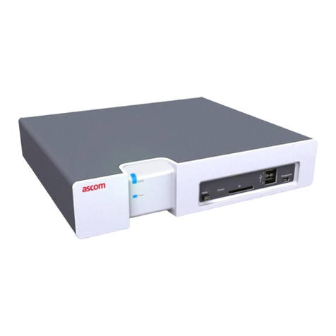
The Elise3 front side has different status indications and is used for maintenance. The LEDs
indicate the status of the product and the management port makes it possible to have
direct connection to the product. It also has an SD card slot and two USB ports for use with
external temporary devices.
3.1 Overview of Connectors, Buttons and LEDs
Figure 1. Front side
Status
Power
Mode Restart SD Management
1
2
a
b c de fg
Front side
(a) Status LED
Indicates the product status
(b) Power LED
Indicates the power status
(c) Mode button
Used as a momentary push button with a blue LED. Used for placing the
product into specific modes by different push patterns.
(d) Restart button
A hole button that requires a paper clip (or similar) to be able to push. Used
for performing controlled restart and forced restart.
(e) SD card slot
Used as external memory for storing configuration and data. This is a
software dependent feature.
(f) USB ports
Used for upgrading of the Boot software on the field.
(g) Management
Mini-USB port for device management

TD 92679EN
22 November 2013 / Ver. G
Installation Guide
Elise3
6
3. Description
Figure 2. Rear side
+V
Ext
In
1
In
2
Out
1
Out
2
GND
Ext
Error
1 2
12-24 V DC 1A
+ -
A-bus
1 2
LON
1 2
COM 1
COM 2
LAN 1
LAN 2
S900
S900
100-240V 275mA 50-60 Hz
+V
Ext
In
1
In
2
Out
1
Out
2
GND
Ext
Error
1 2
12-24 V DC 1A
+ -
A-bus
1 2
LON
1 2
abc
de f g fh i
j
Rear side
(a) COM ports
Used for connection of RS232 communication
Note applicable for the Elise3 Lite version.
(b) LAN ports
LAN 1 is used for connection of 10baseT or 100baseT Ethernet TCP/IP
network
LAN 2 is currently not used (for future releases)
(c) S900 connections (A-bus)
Modular jacks (RJ45) used for connection of Ascom Paging System, Output
modules, and Alarm Modules with modular system bus cabling.
Not applicable for the Elise3 Lite version.
(d) A-bus
Screw connector for connection of Ascom Paging System, and Output
modules when modular system bus cable is not used. Not applicable for the
Elise3 Lite version.
(e) LON connections
Screw connector for connection of the LON bus. Applicable for the Elise3
LON version only.
(f) V+ Ext/GND Ext connections
External 12 V power supply to provide galvanic isolation of the inputs and
outputs, see below.
(g) In1/In2 and Out1/Out2 connections
Used for connection of AUX inputs and AUX outputs
(h) Error connection
Used for connection of a lamp/siren used to indicate if the product is
malfunctioning.
(i) 12-24 Vdc connection
Used for connection of external backup battery/power supply.

TD 92679EN
22 November 2013 / Ver. G
Installation Guide
Elise3
7
3. Description
3.2 Label for IP Address/Host Name
To facilitate future support and access to the module, the product’s IP address or Host name
can be printed on a blank label and attached as shown in figure 3.
The blank label is found on the back side of the Getting started document: “Elise3 –
EMBEDDED LINUX SERVER INCLUDING SAFETY INFORMATION”, included in the delivery.
Figure 3. Label for IP address or host name
IP address / Host name
3.3 LED Indications
The LEDs show different colors to determine type of information and have different flashing
frequency for showing the priority.
(j) 100-240 Vac
Used for connection of supply voltage.
Colors
Red Fault indication
Yellow Mode indication
Blue Normal operation (OK)

TD 92679EN
22 November 2013 / Ver. G
Installation Guide
Elise3
8
3. Description
Flashing patterns
Figure 4. LED indications
* also used if the Power parameter conflicts with the actual setup.
Red
Red
Blue
Blue
Yellow
Yellow
Status LED
Blue
Mode LED
Blue
Blue
Yellow
Yellow
Blue
Status OK
Starting up/shutting down
Feedback (1 sec.)
Error/fault
Warning
Boot mode
Demonstation mode
Waiting for automatic
startup (1 min.)
Troubleshoot mode and
during firmware upgrade
Mass storage mode
Standby module synchronized
Standby module during
synchronization Yellow
Power LED
Blue
Blue
Yellow
Status LED Mode LED
Blue
Blue
Confirmation is done and settings
can be activated
Secured settings
Indicates that manual confirmation is required
Red
Power LED
Closing down caused by
low voltage
Power
Power OK Blue
Red
Low voltage*
Active module during
synchronization
Active module synchronized
Blue
Blue
Red
Blue
3.4 Operating Mode
Besides normal operation the Elise3 can be operated in three other modes, that is, Boot
Mode, Demonstration Mode and Troubleshoot Mode.
3.4.1 Normal Operation
All configuration and settings for the Elise3’s software, such as maintenance, software
upgrade and troubleshooting, are performed in the web user interface described in the
product’s user documentation.
3.4.2 Boot Mode
If the software cannot be accessed, the Elise3 can be set in Boot Mode from the web user
interface. From this interface, it is possible to install new software, start Troubleshoot Mode,
see settings and to reset the module back to factory default settings1.
Placing the Elise3 in Boot Mode is performed manually by the user but if the Elise3 detects
several major errors the module can place itself in Boot Mode.
See 5. Working in Boot Mode on page 27.
1. Network settings such (IP address, Host name, etc.) will not be changed when resetting back to factory default.

TD 92679EN
22 November 2013 / Ver. G
Installation Guide
Elise3
9
3. Description
3.4.3 Demonstration Mode
Demonstration Mode makes it possible to run the Elise3’s software for two hours with full or
almost full functionality, with or without a valid license. Exact functionality is software
dependent. For more information about the functionality during demonstration mode, see
the product’s documentation. See 6. Demonstration Mode on page 30.
3.4.4 Troubleshoot Mode
Troubleshoot Mode makes it possible to troubleshoot the system and access log files when
it is impossible to access and troubleshoot in the software running on the Elise3, i.e. in
Troubleshoot Mode no application is started.
Troubleshoot Mode is started from the Boot Mode GUI, see 8.1 Troubleshooting from Boot
Mode on page 34.

TD 92679EN
22 November 2013 / Ver. G
Installation Guide
Elise3
10
4. Installation and Configuration
4. Installation and Configuration
The Elise3 can be mounted vertically on a wall or be placed horizontally in a 19” rack. It must
be fixed by screws or other fixtures to the wall or rack, and must not be easily movable.
Figure 5. Recommended installation and configuration procedure
Connect the
supply voltage
Access the
application
Mount the
hardware
Basic
configuration
Connect
to required
equipment
4.1 Mounting
4.1.1 Environmental
The Elise3 shall be placed in an environment with an ambient temperature between 0°C to
+40°C (32°F to 104°F). Relative humidity: 30 - 85% RH (non condensing).
4.1.2 Installations Requiring Seismetic Considerations
When installing the Elise3 in geographic regions with seismic conditions and special
considerations, check regional codes and regulations to determine if any requirements exist
and apply for securely mounting ITE equipment.
After the desired rack or cabinet is installed, install the Elise3 in accordance with the
instructions in 4.1.3 Wall Mounting and 4.1.4 Rack Mounting on page 11.
4.1.3 Wall Mounting
Four screws size 3.5×40 mm (0.14×1.6 in) together with four wall plugs and four screws
size M3×6 mm (0.12×0.24 in), are delivered with the product. The M3×6 screws are used
for attaching the assembly brackets to the module. Use the 3.5×40 mm (0.14×1.6 in)
screws for walls made of wood. For walls made of concrete and bricks use them together
with the wall plugs. For other types of walls use suitable screws and plugs according to wall
material.
IMPORTANT: When mounted on a wall, it is of great importance that the connections are
located in a vertical plane.
1 Fasten the supplied assembly brackets on the bottom side of the Elise3.
2 Use the supplied screws and wall plugs (or other suitable screws and plugs
dependent on wall material) and mount the Elise3 as shown in figure 6.

TD 92679EN
22 November 2013 / Ver. G
Installation Guide
Elise3
11
4. Installation and Configuration
Figure 6. Mounting on a wall
Connectors Connectors
4.1.4 Rack Mounting
The Elise3 can be either front mounted or reverse mounted in a 19” rack. Accessories for
mounting in a rack (ordered separately).
NOTE: Screws for fastening the assembly brackets in the rack are not included in the
delivery.
Front mounted single
Front mounting a single Elise3 requires the standard 19´´ rack kit.
Item No. Rack
660324 Standard 19” rack kit:
Small left/right brackets for two front mounted Elise3
and one big bracket for one front mounted hardware.
660325 Reverse 19” rack kit:
Small left/right brackets for two reverse mounted Elise3
and one big bracket for one reverse mounted Elise3.

TD 92679EN
22 November 2013 / Ver. G
Installation Guide
Elise3
12
4. Installation and Configuration
1 Fasten the big assembly bracket on the right side of the Elise3 and the small
assembly brackets on the left side, as shown in the figure below.
2 Fasten the assembly brackets in the rack as shown in the figure below (screws not
included).
Front mounted double
Front mounting of double Elise3 requires the standard 19” rack kit.
1 Use the supplied assembly brackets and fasten the two Elise3 together, both on the
rear side and on the bottom side, as shown in the figures below.

TD 92679EN
22 November 2013 / Ver. G
Installation Guide
Elise3
13
4. Installation and Configuration
2 Use the two small standard assembly brackets and fasten one on the right front side
and the other on the left front side.
3 Fasten the assembly brackets in the rack as shown in figure below (screws not
included).
Rear mounted single
Rear mounting of single an Elise3 requires the reverse 19” rack kit.
1 Fasten the big assembly bracket on the right side of the Elise3 and the small
assembly brackets on the left side, as shown in the figure below.

TD 92679EN
22 November 2013 / Ver. G
Installation Guide
Elise3
14
4. Installation and Configuration
2 Fasten the assembly brackets in the rack as shown in the figure below (screws not
included).
Rear mounted double
Rear mounting of double Elise3 require the reverse 19” rack kit.
1 Use the supplied assembly brackets and mount the two Elise3 together, both on the
rear side and on the bottom side as shown in figure below.
2 Use the two small reverse assembly brackets and fasten one on the right rear side
and the other on the left rear side.
Other manuals for Elise3 Lite
1
This manual suits for next models
3
Table of contents
Other ASCOM Server manuals
Popular Server manuals by other brands
Hewlett Packard Enterprise
Hewlett Packard Enterprise HPE ProLiant XL225n Gen10 Plus Maintenance and service guide
NComputing
NComputing L130 user manual
Dell
Dell PowerEdge 1955 installation guide
Dell
Dell 100 Series Hardware installation guide
Harman
Harman AMX Vision V2-MASTER-0300 instruction manual

Avaya
Avaya S8500 Series Job aid
