Ascon tecnologic H3 Line User manual

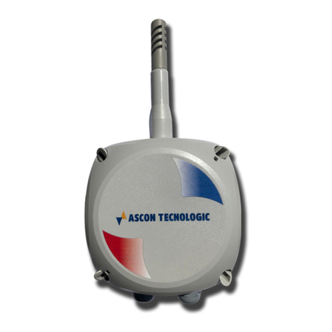
Humidity &
Temperature Transmitter
H3 Line
User Guide
M.I.U. H3 - 1/11.02
Cod. J30-478-1AH3 E

Copyright © 2007, 2011 Ascon Tecnologic Srl
All rights reserved
No part of this document may be stored in a retrieval system, or transmitted in
any form, electronic or mechanical, without prior written permission of Ascon
Tecnologic Srl.
Ascon has used the best care and effort in preparing this manual and believes
that the information contained in this publication is accurate.
As Ascon Tecnologic continues to improve and develop products, the information
contained in this manual may also be subject to change. Ascon Tecnologic
reserves the right to change such information without notice.
Ascon Tecnologic makes no warranty of any kind, expressed or implied, with
regard to the documentation contained in this manual. Ascon Tecnologic shall
not be liable in any event - technical and publishing error or omissions - for any
incidental and consequential damages, in connection with, or arising out of the
use of this manual.
sigmadue
®
, gammadue
®
and deltadue
®
, are trademarks of Ascon Tecnologic Srl.
All other trade names or product names are trademarks or registered trademarks.
Ascon Tecnologic srl
Headquarters:
via Indipendenza 56,
27029 Vigevano (PV)
Phone +39 02 333 371
www.ascontecnologic.com
Milan office: Via Falzarego 9/11,
20021 Baranzate (MI)
Fax +39 02 350 4243

INDEX
iii
Preface . . . . . . . . . . . . . . . . . . . . . . . . . . . . . . . . . . . . . . . . . . . . . . . . . . vii
User Requirements . . . . . . . . . . . . . . . . . . . . . . . . . . . . . . . . . . . . . . . vii
Purpose of this manual . . . . . . . . . . . . . . . . . . . . . . . . . . . . . . . . . . . . vii
Using this manual . . . . . . . . . . . . . . . . . . . . . . . . . . . . . . . . . . . . . . . . viii
Getting started . . . . . . . . . . . . . . . . . . . . . . . . . . . . . . . . . . . . . . . . . . . viii
Related documents . . . . . . . . . . . . . . . . . . . . . . . . . . . . . . . . . . . . . . . ix
Current documentation on Internet . . . . . . . . . . . . . . . . . . . . . . . . . . . ix
We are interested in your comments . . . . . . . . . . . . . . . . . . . . . . . . . . ix
Legal statement . . . . . . . . . . . . . . . . . . . . . . . . . . . . . . . . . . . . . . . . . . ix
Validity of documentation . . . . . . . . . . . . . . . . . . . . . . . . . . . . . . . . . . . ix
Chapter 1
Getting started . . . . . . . . . . . . . . . . . . . . . . . . . . . . . . . . . . . . . . . 1
1-1 Product description . . . . . . . . . . . . . . . . . . . . . . . . . . . . . . . . . . . . . . . 1
1-2 Ordering Code . . . . . . . . . . . . . . . . . . . . . . . . . . . . . . . . . . . . . . . . . . . 2
1-3 Hardware configuration (1st part of the Ordering Code) . . . . . . . . . . . 3
1-3-1 Mounting type (fields A and B of the Ordering Code) . . . . . . 3
1-3-2 Probe material (field C of the Ordering Code) . . . . . . . . . . . 3
1-3-3 Sensor protection filter (field D of the Ordering Code) . . . . . 3
1-4 Output configuration (2nd part of the Ordering Code) . . . . . . . . . . . . . 4
1-5 Accessories configuration (3rd part of the Ordering Code) . . . . . . . . . 4
1-6 Transmitter configuration . . . . . . . . . . . . . . . . . . . . . . . . . . . . . . . . . . . 5
1-6-1 Base configuration . . . . . . . . . . . . . . . . . . . . . . . . . . . . . . . . 5
1-6-2 Advanced configuration . . . . . . . . . . . . . . . . . . . . . . . . . . . . 5
1-7 Usage . . . . . . . . . . . . . . . . . . . . . . . . . . . . . . . . . . . . . . . . . . . . . . . . . 5
1-7-1 Display . . . . . . . . . . . . . . . . . . . . . . . . . . . . . . . . . . . . . . . . . 5
Chapter 2
Start up . . . . . . . . . . . . . . . . . . . . . . . . . . . . . . . . . . . . . . . . . . . . . 7
2-1 Installation . . . . . . . . . . . . . . . . . . . . . . . . . . . . . . . . . . . . . . . . . . . . . . 7
2-1-1 Precautions . . . . . . . . . . . . . . . . . . . . . . . . . . . . . . . . . . . . . 7
2-2 Dimensions . . . . . . . . . . . . . . . . . . . . . . . . . . . . . . . . . . . . . . . . . . . . . 8
2-2-1 Transmitter . . . . . . . . . . . . . . . . . . . . . . . . . . . . . . . . . . . . . . 8
2-2-2 Mounting holes and mounting accessories . . . . . . . . . . . . . 9
2-3 Electrical connections . . . . . . . . . . . . . . . . . . . . . . . . . . . . . . . . . . . . . 10
2-3-1 Version with internal removable spring terminals
and M16 conduits . . . . . . . . . . . . . . . . . . . . . . . . . . . . . . . . . 10
2-3-2 Version with 5 pole M12 connectors . . . . . . . . . . . . . . . . . . . 11
Chapter 3
Basic Functions . . . . . . . . . . . . . . . . . . . . . . . . . . . . . . . . . . . . . . 13
3-1 Transmitter functions . . . . . . . . . . . . . . . . . . . . . . . . . . . . . . . . . . . . . . 13
3-1-1 Data acquired from the Humi-Chip . . . . . . . . . . . . . . . . . . . . 13
3-1-2 Data displayed . . . . . . . . . . . . . . . . . . . . . . . . . . . . . . . . . . . 13

Index (continued)
iv
Chapter 4
Maintenance . . . . . . . . . . . . . . . . . . . . . . . . . . . . . . . . . . . . . . . . 15
4-1 Cleaning/replacing the dust filter . . . . . . . . . . . . . . . . . . . . . . . . . . . . . 15
4-2 Replacement of the “Humi-Chip” module . . . . . . . . . . . . . . . . . . . . . . . 16
Chapter 5
Advanced functions . . . . . . . . . . . . . . . . . . . . . . . . . . . . . . . . . . 17
5-1 Analogue Outputs . . . . . . . . . . . . . . . . . . . . . . . . . . . . . . . . . . . . . . . . 17
5-2 Serial Port Setting . . . . . . . . . . . . . . . . . . . . . . . . . . . . . . . . . . . . . . . . 17
5-3 Commands . . . . . . . . . . . . . . . . . . . . . . . . . . . . . . . . . . . . . . . . . . . . . . 18
5-4 Calibration . . . . . . . . . . . . . . . . . . . . . . . . . . . . . . . . . . . . . . . . . . . . . . 18
5-4-1 “Humi-Chip” sensor calibration . . . . . . . . . . . . . . . . . . . . . . . 18
5-4-2 Sensor replacement . . . . . . . . . . . . . . . . . . . . . . . . . . . . . . . 19
5-5 Date and Time format . . . . . . . . . . . . . . . . . . . . . . . . . . . . . . . . . . . . . 20
5-6 Advanced display configuration . . . . . . . . . . . . . . . . . . . . . . . . . . . . . . 20
Chapter 6
The Modbus Protocol . . . . . . . . . . . . . . . . . . . . . . . . . . . . . . . . . 21
6-1 Communications Lines . . . . . . . . . . . . . . . . . . . . . . . . . . . . . . . . . . . . . 21
6-2 Modbus Functions . . . . . . . . . . . . . . . . . . . . . . . . . . . . . . . . . . . . . . . . 21
6-3 Common Registers and Diagnostics . . . . . . . . . . . . . . . . . . . . . . . . . . 22
6-3-1 MODBUS Exception Responses . . . . . . . . . . . . . . . . . . . . . 22
6-3-2 Diagnostics . . . . . . . . . . . . . . . . . . . . . . . . . . . . . . . . . . . . . . 23
6-4 Discrete data (input and coils) . . . . . . . . . . . . . . . . . . . . . . . . . . . . . . . 23
6-5 Data registers . . . . . . . . . . . . . . . . . . . . . . . . . . . . . . . . . . . . . . . . . . . . 23
6-5-1 Variables and Parameters . . . . . . . . . . . . . . . . . . . . . . . . . . 23
6-5-2 Identity Registers . . . . . . . . . . . . . . . . . . . . . . . . . . . . . . . . . 24
6-5-3 Command registers . . . . . . . . . . . . . . . . . . . . . . . . . . . . . . . 24
6-5-4 Retentive registers . . . . . . . . . . . . . . . . . . . . . . . . . . . . . . . . 24
6-5-5 Configuration registers . . . . . . . . . . . . . . . . . . . . . . . . . . . . . 25
6-5-6 Diagnostic registers . . . . . . . . . . . . . . . . . . . . . . . . . . . . . . . 25
Chapter 7
Commands . . . . . . . . . . . . . . . . . . . . . . . . . . . . . . . . . . . . . . . . . . 27
7-1 Program commands . . . . . . . . . . . . . . . . . . . . . . . . . . . . . . . . . . . . . . . 27
7-1-1 Cmd_Res . . . . . . . . . . . . . . . . . . . . . . . . . . . . . . . . . . . . . . . 27
7-1-2 Cmd_calsens . . . . . . . . . . . . . . . . . . . . . . . . . . . . . . . . . . . . 27
7-1-3 Cmd_cngsens . . . . . . . . . . . . . . . . . . . . . . . . . . . . . . . . . . . . 27
7-2 System Commands . . . . . . . . . . . . . . . . . . . . . . . . . . . . . . . . . . . . . . . 27
7-2-1 Calibration Commands . . . . . . . . . . . . . . . . . . . . . . . . . . . . . 27
7-2-2 Operating System Commands . . . . . . . . . . . . . . . . . . . . . . . 28
Chapter 8
Configuration . . . . . . . . . . . . . . . . . . . . . . . . . . . . . . . . . . . . . . . . 29
8-1 Registers . . . . . . . . . . . . . . . . . . . . . . . . . . . . . . . . . . . . . . . . . . . . . . . 29
8-1-1 Modbus Setting Registers . . . . . . . . . . . . . . . . . . . . . . . . . . . 29
8-1-2 Temperature Engineering Units . . . . . . . . . . . . . . . . . . . . . . 30
8-1-3 Decimal digits . . . . . . . . . . . . . . . . . . . . . . . . . . . . . . . . . . . . 30
8-1-4 Analogue Output Type . . . . . . . . . . . . . . . . . . . . . . . . . . . . . 30
8-1-5 Input Source for Analogue Outputs . . . . . . . . . . . . . . . . . . . 31
8-1-6 Humidity and Temperture Offset Registers . . . . . . . . . . . . . 31

Index (continued)
v
Chapter 9
Configuration Tool . . . . . . . . . . . . . . . . . . . . . . . . . . . . . . . . . . . 33
9-1 System requirements . . . . . . . . . . . . . . . . . . . . . . . . . . . . . . . . . . . . . . 33
9-2 Installing the configuration software . . . . . . . . . . . . . . . . . . . . . . . . . . 33
9-3 Using the configuration software . . . . . . . . . . . . . . . . . . . . . . . . . . . . 33
9-3-1 Configuration software settings . . . . . . . . . . . . . . . . . . . . . . 34
9-3-2 Storing the screen settings into the instrument transmitter . 34
9-3-3 Storing the screen settings as a file . . . . . . . . . . . . . . . . . . . 35
9-3-4 Recalling a previously stored file . . . . . . . . . . . . . . . . . . . . . 35
9-3-5 Printing the configuration . . . . . . . . . . . . . . . . . . . . . . . . . . . 35
9-3-6 Trend Menu . . . . . . . . . . . . . . . . . . . . . . . . . . . . . . . . . . . . . 36
Appendix A
Modbus Address Map . . . . . . . . . . . . . . . . . . . . . . . . . . . . . . . . 37
Appendix B
Characteristics . . . . . . . . . . . . . . . . . . . . . . . . . . . . . . . . . . . . . . . 39
B-1 Technical characteristics . . . . . . . . . . . . . . . . . . . . . . . . . . . . . . . . . . . 39
Appendix C
Troubleshooting . . . . . . . . . . . . . . . . . . . . . . . . . . . . . . . . . . . . . 41
C-1 . . . . . . . . . . . . . . . . . . . . . . . . . . . . . . . . . . . . . . . . . . . . . . . . . . . . . . . 41
C-1-1 . . . . . . . . . . . . . . . . . . . . . . . . . . . . . . . . . . . . . . . . . . . . . . . 41
Appendix D
Warranty . . . . . . . . . . . . . . . . . . . . . . . . . . . . . . . . . . . . . . . . . . . . 43

Index (continued)
vi

vii
Preface
In order to guarantee the safe use of your device, we recommend that you read
this manual carefully. The following notes give you information on how to use
this manual.
User Requirements vii
Purpose of this manual vii
Using this manual viii
Getting started viii
Current documentation on Internet ix
We are interested in your comments ix
Legal statement ix
Validity of documentation ix
User Requirements
The products described in this manual should be installed, operated and
maintained only by qualified application programmers and software engineers,
electricians or persons instructed by them, who are familiar with automation
safety concepts and applicable national standards.
Ascon Tecnologic Srl assumes no liability for damage to any product resulting
from the disregard of information contained in this manual.
Purpose of this manual
This manual contains the information necessary to understand and to configure
the H3 line Humidity and Temperature transmitter.
This manual is written on the assumption that the reader possesses basic
knowledge of Fieldbus techniques, in particular for Modbus. Use this manual if
you are responsible for configuring and installing Ascon Tecnologic modules
with Modbus interface.

Humidity & Temperature Transmitter - H3 Line
viii
Using this manual
Specifications within the text of this manual are given in the International System
of Units (SI), with non SI equivalents in parentheses.
Fully capitalized words within the text indicate markings found on the equipment.
Words in bold style within the text indicate markings found in the Configuration Tools.
Warnings, Cautions and Notes are used to emphasize critical instructions:
DANGER!
Indicates an imminently hazardous situation which, if not avoided, will result in
death or serious injury.
WARNING
Indicates a potentially hazardous situation which, if not avoided, could result in
death or serious injury.
Caution
Indicates a potentially hazardous situation which, if not avoided, may result in
minor or moderate injury, or property damage.
Note: Highlights important information about an operating procedure or the equipment.
For ease of looking for specific information in this manual, we have provided the
following:
• A main table of contents covering all subject matter is provided at the
front of this manual.
• A table of contents covering information within a section or an appendix is
provided at the front of the individual section or appendix.
• Appendices covering specific topics are provided following the last sec-
tion in the manual.
- MODBUS Addresses Map;
- Suggestions and examples;
- Definitions, symbols and conversion tables.
Getting started
In the first section you are introduced to
Ascon Tecnologic
modules basics. The
following sections contain general information that applies to all modules or
module groups of the series. Topics are for example:
• Overview of the product;
• Terminal installation and wiring;
• Common technical data.

Preface
ix
Related documents
For additional information regarding MODBUS in general, refer to the documents
issued by the respective Users Organisations.
If you need specific information on an Ascon Tecnologic, refer to the specific data sheet.
Current documentation on Internet
Make sure you are always working with the latest documentation published. The
latest changes or additional information can be found on the Internet at:
http://www.ascon.it
http://www.asconcorp.com
Ascon Tecnologic
Products pages are to be updated frequently. It is possible
therefore that the Data Sheets published on the Internet would have a publishing
date more recent than the date of this manual.
We are interested in your comments
Ascon Tecnologic srl
makes any effort to improve the quality of its manuals.
Nevertheless errors and omissions are always possible. If you have suggestions
or indications about the content or the form of this manual,
Ascon Tecnologic
srl will
greatly appreciate your comments. You can send an e-mail to:
Legal statement
This manual, including all illustrations contained herein, is copyright protected.
Use of this manual by any third party in departure from the copyright provision is
prohibited. Reproduction, translation, and electronic or photographic archiving or
alteration requires the express written consent of
Ascon Tecnologic
srl.
Ascon Tecnologic
srl reserves the right to make any technical changes that serve
the purpose of technical progress.
External products are always named without reference to patent rights. The
existence of such rights shall not be excluded.
Validity of documentation
This manual mainly contains the description of H3 line Humidity and Temperature
transmitter that was available when this manual was published.
Ascon Tecnologic
srl reserves the right to make any technical extension and
change to the equipment that would serve the purpose of technical progress. Up
to the time that a new manual revision is published, any update or change will be
documented on the Internet at:
http://www.ascon.it
http://www.asconcorp.com

Humidity & Temperature Transmitter - H3 Line
x

1
Chapter 1
Getting started
1-1 Product description
The H3 line transmitters are Humidity and Temperature electronic measuring
instruments that determine measurements by means of a highly accurate,
condensation resistant capacitive sensor integrated in a silicon microchip (the
“Humi-Chip” module).
This technology provides accurate process measurements, reliability and excellent
long-term stability.
The “Humi-chip” module that incorporates the sensor can be easily replaced
without the need for re-calibration; its environmental limits are: 0...100% for
Relative Humidity (RH) and -30...+90°C for Temperature and Stability: <0.5 RH%
per year for Long-term drift.
When purchasing, if the ordering code is correctly composed, the transmitter can
be installed and used with no further settings.
Expert users using the “Controller Explorer” software can easily set the transmitter
parameters. Through the serial port the user can connect the H3 to a Personal
Computer and in this way configure:
• The analogue outputs;
• The alarms.
WARNING
In order to install and use the transmitter, follow the instructions in chapters 1... 4.
The procedure to configure the transmitter parameters can be found at chapters 5...9.

Humidity & Temperature Transmitter - H3 Line
2
1-2 Ordering Code
Hardware options are added to H3 transmitters as required by the user. The options
that are to be installed are specified by the first part of the Ordering Code.
Model:
Line
Mounting - Dimensions
Probe material
Filter
Serial port (option)
LCD Display (option)
Electrical connections
2
nd
Analogue output (option)
1
st
Analogue output (option)
B
A
C D E F G H L
I0
H3 --
Hardware Outputs Accessories
Where:
Example: H3-C20R-111-MD00
Note: In the version with two M12
connectors the RS485 Modbus RTU
serial port excludes the PT100 output.
Mounting Dimensions A B
Wall Ø20 x L110 P 0
Duct Ø20 x L250 C 2
Ø20 x L530 C 5
Remote Ø20 x L160, cable 2 m R 2
Ø20 x L160, cable 5 m R 5
Probe material C
Polycarbonate 0
Filter D
Stainless steel wire mesh R
Sintered S
Te f l o n T
1st Analogue output - Humidity E
Not fitted 0
4... 20 mA/0... 100% RH 1
0... 10 V/0... 100% RH 2
0... 1 V/0... 100% RH 3
2nd Analogue output - Temperature F
Not fitted 0
4...20 mA 1
0...10 V 2
0... 1 V 3
PT100 - IEC751 compliant [note] P
Temperature range (°F on request) G
(if F = 0 or F = P) 0
-30... +70°C 1
-20... +30°C 2
0... 50°C 3
0... 100°C 4
Electrical Connections H
Terminals with M16 conduit M
2 connectors (M + F) M12, IP66 C
LCD Display (option) I
Not fitted 0
Internal LCD Display D
Serial Communications + Special Functions L
Not fitted 0
RS485 Modbus [note] 5

Chapter 1 - Getting started
3
1-3 Hardware configuration (1st part of the Ordering Code)
1-3-1 Mounting type (fields A and B of the Ordering Code)
The H3 line can be installed in different modes also through dedicated accessories:
• Wall installation, mounting the transmitter directly or using the mounting
brackets fitted outside the housing (Order Code: H-SFE2);
• Duct installation (probes of Ø20 mm and 250/530 mm length), also using the
adjustable self-locking flange Ø100 (Order Code: H-SMP01);
• Sensor remote installation (cable of 2 or 5 m long) also with the wall mounting
bracket for remote sensor (Order Code:
H-FLA20
)
.
1-3-2 Probe material (field C of the Ordering Code)
The probe for duct mounting is made of polycarbonate plastic that can be used in
the food and beverage industries.
1-3-3 Sensor protection filter
(field D of the Ordering Code)
Environmental protection for the “Humi-Chip” module is provided by one of three
user selected filter types:
• Wire mesh stainless steel filter with threaded filter protection.
Porosity of 25 µm and response time of 5 s (0...63%) make it suitable for clean
environments dust and moderate wind conditions
.
• Stainless steel sintered filter with threaded connection.
Porosity of 5 µm and response time of 10 s (0...63%) make it suitable for dusty
environments; not moisture resistant.
• Teflon filter with threaded connection.
Porosity of 25 µm and response time of 120 s (0...63%)
make it suitable for
aggressive chemical environments, not suitable with highgrade humidity.
Mounting Dimensions A B
Wall Ø20 x L110 P 0
Duct Ø20 x L250 C 2
Ø20 x L530 C 5
Remote Ø20 x L160, cable 2 m R 2
Ø20 x L160, cable 5 m R 5
Probe material C
Polycarbonate 0
Filter D
Stainless steel wire mesh R
Sintered S
Te f l o n T

Humidity & Temperature Transmitter - H3 Line
4
1-4 Output configuration (2nd part of the Ordering Code)
Using the ordering code, the user can order the configuration of the output ports
necessary for the application:
• Number of analogue outputs (0, 1 or 2);
• Output type (Current/Voltage output, Relative Humidity and Temperature);
• Temperature output range;
•
If the analogue output configuration cannot be specified in the Ordering Code,
the user may configure the outputs with Controller Explorer software (see
“Chapter 5 -
Advanced functions
” for details).
Note: In models with M12 connectors the RS485 Modbus RTU serial port excludes
the PT100 output.
1-5 Accessories configuration (3rd part of the Ordering Code)
The transmitter allows the installation of some optional accessories in order to
guarantee good application flexibility.
The available options are:
• Terminals or M12 connectors;
•Display;
• RS485 communications port.
Note: In models with M12 connectors the RS485 Modbus RTU serial port excludes
the PT100 output.
1st Analogue output - Humidity E
Not fitted 0
4... 20 mA/0... 100% RH 1
0... 10 V/0... 100% RH 2
0... 1 V/0... 100% RH 3
2nd Analogue output - Temperature F
Not fitted 0
4...20 mA 1
0...10 V 2
0... 1 V 3
PT100 - IEC751 compliant [note] P
Temperature range (°F on request) G
(if F = 0 or F = P) 0
-30... +70°C 1
-20... +30°C 2
0... 50°C 3
0... 100°C 4
Electrical Connections H
Terminals with M16 conduit M
2 connectrors (M + F) M12, IP66 C
LCD Display (option) I
Not fitted 0
Internal LCD Display D
Serial Communications + Special Functions L
Not fitted 0
RS485 Modbus [note] 5

Chapter 1 - Getting started
5
1-6 Transmitter configuration
1-6-1 Base configuration
If all hardware configurations and options can be specified in the Ordering Code,
the transmitter can be installed and used immediately.
1-6-2 Advanced configuration
If all hardware configurations and options are not specified in the Ordering Code,
the transmitter can be configured with the Controller Explorer software.
1-7 Usage
The main function of the instrument is to read the environmental conditions from
the “Humi-Chip” sensor: Relative Humidity (RH), Temperature (T). After the
values are converted they can be retransmitted through the analogue outputs,
displayed (on the optional display) and can be used to configure the alarms.
The measures together with the min./max. values are always available as Modbus
variables. The limit values can be reset through the serial line and the Modbus
protocol.
No buttons are available on the transmitter. The only operator interface is through
the Modbus protocol.
When the analogue outputs are installed in the instrument, each can be configured
to retransmit the value of one of the 2 variables RH, T. During the configuration
phase the user can also select the transmission mode (current/voltage).
1-7-1 Display
The optional LCD display shows 3 lines of 16 characters each. All of the
operations to setup, read and program the transmitter are performed through the
serial communications port and the Modbus protocol as there are no inputs to
send commands to the H3. On the LCD the variables (RH, T) can be displayed as
well as, when necessary, the alarms and the status of the relay output.
Initialisation
During the start up phase the transmitter displays the following messages:

Humidity & Temperature Transmitter - H3 Line
6
Normal
operation
In normal operation on the display are shown the values of the variables read from
the “Humi-Chip” sensor (RH and T).
Errors The error conditions are immediately displayed and remains on the display while
the error cause is present or, at least, 3 seconds.

7
Chapter 2
Start up
2-1 Installation
2-1-1 Precautions
“Humi-Chip” measurement module incorporates an integrated temperature sensor.
The measured values are correct when the “Humi-Chip” Humidity and
Temperature are both in equilibrium with the surrounding ambient conditions.
For optimum performance, the following recommendations must be observed:
1. Install the sensor in the most representative location of the ambient to be
controlled;
2. Avoid direct exposure to sun and atmospheric agents;
3. Avoid installing the sensor next to heaters, coolers, steam vents and
humidifiers;
4. Avoid turbulences which can generate unstable pressures.

Humidity & Temperature Transmitter - H3 Line
8
2-2 Dimensions
2-2-1 Transmitter
70 max.
35 max.
CH 15
CH 19
Wall mounting
Duct mounting
Remote sensor mounting
Conduit M16 M12 Connector
Mounting
Output
100
100
61
110
2000/5000
Ø20
50
160
250/530
Ø20
48.5

Chapter 2 - Start-up
9
2-2-2 Mounting holes and mounting accessories
10063
85
100
112
85
64
124
4 mounting
holes Ø11
4 mounting
holes Ø4.5
4 mounting
holes Ø4.5
Wall mounting: H3-P... and H3-R...
Wall mounting bracket for remote sensor
a) 4 internal holes (std.) b) 2 brackets (optional)
Ø75
5.5
Ø100
55 max.
Ø29.5
Ø22
Mounting for Duct model: H3-C...
Adjustable flange Ø100 self locking
Ø4
5
1050
50
10
Ø4
20
==
==
47.5
CH 36
CH 30
50 max.
Ø29.5
Ø22

Humidity & Temperature Transmitter - H3 Line
10
2-3 Electrical connections
2-3-1 Version with internal removable spring terminals and M16 conduits
Notes: 1. Three M16 conduit for output cables up to Ø8.5 mm.
2- Spring terminal strip for cable sections of 0.14...1.5mm2(AWG28...AWG16).
- The AO1 output is isolated from the optional AO2 output.
Analogue
output
terminals
Power supply
and
relay output
Serial
communications
port
Note:
When the RS485 communications port is not present in the transmitter on the same
terminals are present the signals of the embedded RS232 communications port.
PT100
output
terminals
PT100
Temperature
output (opt.)
AO2 output
Humi-chip
module
AO1 output
RS485 Serial
communications
port (opt.)
[1]
[2]
[2]
ACB
Display
(opt.)
[2]
Power supply
AL relay
output
[2]
Analogue
outputs
AO1 and AO2 set as current outputs
(0/4... 20 mA)
AO1 Analog
output
max. load 500Ω
at 24 Vdc
max. load 500Ωat 24 Vdc
AO2 Analog
output (opt.)
-+
-+
AO2
+-
AO1
+-
AO1 Analog
output
AO1 and AO2 set as voltage outputs
(0... 1, 0... 5, 0...10Vdc)
AO2 Analog
output (opt.)
-
+
-
+
AO2
+-
AO1
+-
Power supply
AL relay
output
RS485
GND
b
B
A
PT100
Temperature
output
Table of contents
Other Ascon tecnologic Transmitter manuals