Ascon tecnologic H6 Series User manual

Ascon Tecnologic - H6 Series - USER MANUAL - PAG. 1
H6
RELATIVE HUMIDITY AND
TEMPERATURE TRANSMITTER
User manual
21/09 - Code.: ISTR_M_H6_E_01_--
Ascon Tecnologic S.r.l.
Viale Indipendenza 56, 27029 Vigevano (PV) - ITALY
Tel.: +39 0381 69871 - Fax: +39 0381 698730
Sito: http:\\www.ascontecnologic.com
e-mail: [email protected]
PREFACE
m
This manual contains the information necessary for
the product to be installed correctly and also in-
structions for its maintenance and use; we therefore
recommend that the utmost attention is paid to the
following instructions and to save it.
This document is the exclusive property of Ascon Tecnologic
S.r.l. which forbids any reproduction and divulgation, even
partially, of the document, unless expressly authorized.
Ascon Tecnologic
S.r.l. reserves the right to make any formal
or functional changes at any moment and without any notice.
Ascon Tecnologic S.r.l. and its legal representatives do not
assume any responsibility for any damage to people, things
or animals deriving from violation, wrong or improper use or
in any case not in compliance with the instrument features.
m
Whenever a failure or a malfunction of the device
may cause dangerous situations for persons, thing
or animals, please remember that the plant has to be
equipped with additional electromechanical devices
which will guarantee safety.
1 INSTRUMENT DESCRIPTION
1.1 General description
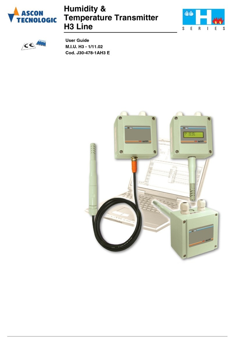
H6s are single or dual channel relative humidity and
temperature transmitters for industrial applications.
Both models have a temperature sensor, the different on-
board electronics means that in the single-channel model, the
temperature measure is intended for reading by the user.
The transmitters are supplied already calibrated to adapt them
to the customer’s needs.
Versions for wall or duct mounting are available.
2 USAGE WARNINGS
2.1 Admitted use
m
The instrument has been projected and manufac-
tured as a measuring and control device to be used
according to EN60730-1 at altitudes operation below
2000 m.
Using the instrument for applications not expressly permitted
by the above mentioned rule must adopt all the necessary
protective measures.
The instrument must not be used in dangerous environ-
ments (flammable or explosive) without adequate protections.
The installer must ensure that the EMC rules are respected,
also after the instrument installation, if necessary using
proper filters.
3 INSTALLATION WARNINGS
3.1 Dimensions [mm]
3.1.1 Wall mounting
70
Mounting
bracket
Ø4
95 (bottom)
104
118
95 (bottom)
104110
3.1.2 Duct mounting
250/530
Ø20
48.5

Ascon Tecnologic - H6 Series - USER MANUAL - PAG. 2
3.1.3 Remote sensor mounting
2160/5160/10160
Ø20
50
160
M16 cable gland outlet
35 max.
CH 19
Remote sensor mounting
70
104
Mounting
brackets
Ø4
104
114... 122
114... 122
104
Ø4
9
4
9
4
Duct mounting - adjustable flange Ø100 self
locking (AH-FLA20 optional)
Ø75
5.5
Ø100
55 max.
Ø29.5
Ø22 CH 36
4 mounting
holes Ø11
Bracket for remote sensor wall mounting
(AH-SMP01 optional)
Ø4
5
1050
50
10
Ø4
20
==
==
47.5
CH 30
50 max.
Ø29.5
Ø22
3.2 Electrical connections
Carry out the electrical wiring by connecting only one wire to
each terminal, according to the following diagram, checking
that the power supply is the same as that indicated on the
instrument and that the load current absorption is no higher
than the maximum electricity current permitted.
It is also recommended to:
–Adequately protect the circuits connected to the instrument
with devices (e.g. fuses) suitable for the circulating currents.
–Use cables with insulation appropriate to the voltages,
temperatures and operating conditions.
–Make sure that the input sensors cables are kept away from
supply cables and other power cables in order to avoid the
induction of electromagnetic disturbances.
–If shielded cables are used for wiring, it is recommended to
connect the protective shield to earth at one side only.
3.2.1 Electrical wiring
GND/WHT
SDA/BLU
SCL/YEL
VCC/BLK
USB
2143
LH1LH2
S5354-01
SEM71
HM/PM
Input
terminals
(factory
reserved)
USB
(factory
reserved)
Channel 1
output
(power supply)
Channel 2
output
Sensors
Temperature
RH
CPU
+
+-
-
+
-
2
1
4
3
2 channel version only
Ch1: (RH output)
4... 20 mA
10... 30 VDC
RL
Ch2: (Temp. °C)
4... 20 mA
+-
10... 30 VDC
RL
Note: Insulation between CH1 and CH2: 500 VDC.

Ascon Tecnologic - H6 Series - USER MANUAL - PAG. 3
4 PROBLEMS AND MAINTENANCE
4.1 Cleaning
We recommend cleaning of the instrument only with a slightly
wet cloth using water and not abrasive cleaners or solvents.
4.2 Disposal
The appliance (or the product) must be
disposed of separately in compliance
with the local standards in force on
waste disposal.
5 WARRANTY AND REPAIRS
The instrument is under warranty against manufacturing flaws
or faulty material, that are found within 18 months from deliv-
ery date. The warranty is limited to repairs or to the replace-
ment of the instrument.
The eventual opening of the housing, the violation of the in-
strument or the improper use and installation of the product will
bring about the immediate withdrawal of the warranty effects.
In the event of a faulty instrument, either within the period
of warranty, or further to its expiry, please contact our sales
department to obtain authorisation for sending the instrument
to our company.
The faulty product must be shipped to Ascon Tecnologic with
a detailed description of the faults found, without any fees or
charge for Ascon Tecnologic, except in the event of alternative
agreements.
6 TECHNICAL DATA
6.1 Input characteristics
RH Range: 0... 100% RH;
RH Accuracy:
Typical: ±2% (±5% max.) between 10... 90%;
RH Thermal Stability: 0.01%/°C;
Temperature Range: -30... 70°C;
Temperature Accuracy: ±0.2°C
between
-20... +70°C;
Temperature
Thermal Stability: 0.1%/°C;
Dew point: Mathematically derived from %RH and temperature;
DT: Mathematically derived from %RH and temperature.
6.2 Output characteristics (Ch1, Ch2)
Output type : 2 wire (4... 20 mA) current loop;
Accuracy:
(mA output/2000) or 5mA, whichever is the greater;
Current loop effect: 0.2 mA/V;
Thermal drift: 0.1 mA/°C;
Max. Output: 20.5 mA;
Min. Output: 3.9 mA;
Max. output load: [(Vsupply - 10)/20] kW(es: 700W@ 24 V);
Channel isolation: 500 Vdc, 48 Vdc working;
Connection type: 2 Screw terminal “Type 4” connectors.
Note: The transmitter circuits are powered through CH1,
therefore the main channel CH1 must always be pow-
ered to obtain the correct operation of the secondary
channel CH2.
6.3 General characteristics
Ch1, Ch2 Power supply: 10... 30 VDC SELV;
Response time: 1 second;
Operating temperature:
Electronics housing: -20... +70°C;
Probe: -30... +70°C;
Approvals:
EMC - BS EN 61326:
Electrical equipment for measurement control and
laboratory use.
BS EN 60529: Ingress protection;
Directive 2011/65/EU: RoHS.
m
The required configuration must be specified at order
time. If the range is not specified, the transmitter is
shiped with default values:
CH1: 0... 100% RH (error signal: 21.5 mA);
CH2: 0... 50°C (error signal: 21.5 mA).
7 ORDER CODE
a: CASE
P0 = Wall mounting
C2 = Duct mounting Ø 20 - L = 250 mm
C3 = Duct mounting Ø 20 - L = 390 mm
C5 = Duct mounting Ø 20 - L = 530 mm
R1 = Remote mounting - Cable length 10 m
R2 = Remote mounting - Cable length 2 m
R3 = Remote mounting - Cable length 5 m
b: PROBE MATERIAL
0 = PVDF Plastic probe
d: HUMIDITY OUTPUT RANGE
1 = 4... 20 mA/0... 100% RH
d: FILTER
R = Stainless steel wire mesh
S = Stainless steel sintered filter
T = Teflon filter
cab d
e: TEMPERATURE OUTPUT
0 = Not present
1 = 4... 20 mA
4 = Dew Point - 4... 20 mA
7 = ∆T - 4... 20 mA
e f g-H6
MODEL
H6 = Relative Humidity and Temperature Transmitter
f: TEMPERATURE OUTPUT RANGE
1 = -30... +70°C
g: CONNECTIONS
M = 2 Removable screw type 4
connectors with M16 cable
gland outlet

Ascon Tecnologic - H6 Series - USER MANUAL - PAG. 4
This manual suits for next models
1
Other Ascon tecnologic Transmitter manuals