manuals.online logo
Brands
  1. Home
  2. •
  3. Brands
  4. •
  5. Ascon tecnologic
  6. •
  7. Transmitter
  8. •
  9. Ascon tecnologic ATT1 Installation and operation manual

Ascon tecnologic ATT1 Installation and operation manual

Ascon Tecnologic - ATT1/ATT1-I - ENGINEERING MANUAL - PAG. 1
ATT1
SIGNAL TRANSMITTER
FOR ALL SENSOR TYPES
ATT1
not insulated model
ATT1-I
insulated model
Engineering manual
20/11 - Code: ISTR_M_ATT1_E_04_--
ASCON TECNOLOGIC S.r.l.
Viale Indipendenza 56, 27029 - VIGEVANO (PV) ITALY
TEL.: +39 0381 69871 - FAX: +39 0381 698730
http:\\www.ascontecnologic.com
e-mail: [email protected]
FOREWORD
This manual contains the information necessary for the
installation of the product, we therefore recommend that
the utmost attention is paid to the following instructions
and to save it.
This document is exclusive property of Ascon Tecnologic which
forbids any reproduction and disclosure, even in part, of the
document, unless expressly authorized. Ascon Tecnologic
reserves the right to make any formal or functional changes at
any moment and without any notice.
Ascon Tecnologic and its legal representatives do not assume
any responsibility for any damage to people, things or animals
deriving from violation, wrong or improper use or in any case not
in compliance with the instrument features.
Whenever a failure or a malfunction of the device
may cause dangerous situations for persons, thing
or animals, please remember that the plant must be
equipped with additional electromechanical devices
which will guarantee safety.
Disposal
The appliance (or the product) must be
disposed of separately in compliance
with the local standards in force on waste
disposal.
INSTRUMENT DESCRIPTION
General description
ATT1/ATT1-I is a signal transmitter (Not insulated/Insulated)
capable of accepting in input various types of sensors and
retransmitting their signals with a programmable range.
The transmitter accepts input signals from:
Pt100
Measuring range: -200... +800°C, type of connection:
2, 3, 4 wires, accuracy: 0.1% fs ±10 μA;
Pt1000
Measuring range: -200... +800°C, type of connection:
2 wires, accuracy: 0.1% fs ±10 μA;
Ni100
Measuring range: -60... +180°C, type of connection:
2, 3, 4 wires, accuracy: 0.5% fs ±10 μA;
TC B
Measuring range: 40... 1820°C, the accuracy: 0.2% fs ±10 μA
(only in the range 900... 1800°C);
TC E
Measuring range: -200... +940°C, accuracy: 0.2% fs ±10 μA;
TC J
Measuring range: -200... +1200°C, accuracy: 0.2% fs ±10 μA;
TC K
Measuring range: -200... +1340°C, accuracy: 0.2% fs ±10 μA;
TC N
Measuring range: -200... +1280°C, accuracy: 0.2% fs ±10 μA;
TC R
Measuring range: -40... +1760°C, accuracy: 0.2% fs ±10 μA
(
only in the range 400... 1760°C);
TC S
Measuring range: -40... +1760°C, accuracy: 0.2% fs ±10 μA
(
only in the range 400... 1760°C);
TC T
Measuring range: -200... +400°C, accuracy: 0.2% fs ±10 μA
(
only in the range
-100... +400°C);
mV
Measuring range: -10... +70 mV, accuracy: 0.1% fs;
Potentiometer 10... 400 Ω
type of connection: 2, 3, 4 wires;
accuracy: 0.1% fs ±10 μA;
Poteniometer 10... 4000 Ω
type of connection: 2 wires,
accuracy: 0.1% fs ±10 μA.
It transmits, on the output,
4... 20 mA
current signals.
The transmitter can be programmed using an Android Smart-
phone equipped with the NFC functionalities (Near Field Commu-
nications) and the APP ATNfc (available, free of charge, on Google
store) or using a PC with the AFC1 transmitter and the ATNfcSoft
program (downloadable, free of charge, from our Internet site).
Instrument description
2
6
54
3
1
Vdc
+Out
mA
AB
B1 A1
Tc
NFC
-
+
PWR
7..30Vdc
1
3
4
2
6
7
5
1, 2
Power/Output terminals (2 wires transmitter);
3, 4, 5, 6
Input terminals;
7
Orange
label:
Not isolated
transmitter (
ATT1
),
Blue
label:
Isolated
trasmitter (
ATT1-I
).
Ascon Tecnologic - ATT1/ATT1-I - ENGINEERING MANUAL - PAG. 2
INSTALLATION INFORMATION
Dimensions
45 23
2
6
4
3
1
Vdc
+
mA
AB
B1 A1
Tc
NFC
-
+
PWR
7..30Vdc
5
Out
Electrical connections
Carry out the electrical wiring by connecting only one wire to each
terminal and according to the following diagrams:
Pt100, Pt1000 and Ni100 Sensors
2
6
4
3
1
Vdc
+
mA
AB
B1 A1
Tc
NFC
-
+
PWR
7..30Vdc
5
Out 2
6
4
3
1
Vdc
+
mA
AB
B1 A1
Tc
NFC
-
+
PWR
7..30Vdc
5
Out 2
6
4
3
1
Vdc
+
mA
AB
B1 A1
Tc
NFC
-
+
PWR
7..30Vdc
5
Out
2 wires 3 wires 4 wires
BA BB
1A
A1
BB1A
Note:
The
PT1000
sensors must be connected in
2 wires
mode.
TC K, S, R, J, T, N, B, E Sensors
2
6
4
3
1
Vdc
+
mA
AB
B1 A1
Tc
NFC
-
+
PWR
7..30Vdc
5
Out
2
6
4
3
1
Vdc
+
mA
AB
B1 A1
Tc
NFC
-
+
PWR
7..30Vdc
5
Out
2
6
4
3
1
Vdc
+
mA
AB
B1 A1
Tc
NFC
-
+
PWR
7..30Vdc
5
Out
+−
+−
+− +−
+− +
−+
−
Differential measure
between 2 TC of the
same type
Note: Exclude the CJ
compensation
+− +−
Average temperature measure
between multiple TCs of the
same type
10... 400
W
and 10... 4000
W Potentiometer
2
6
4
3
1
Vdc
+
mA
AB
B1 A1
Tc
NFC
-
+
PWR
7..30Vdc
5
Out 2
6
4
3
1
Vdc
+
mA
AB
B1 A1
Tc
NFC
-
+
PWR
7..30Vdc
5
Out 2
6
4
3
1
Vdc
+
mA
AB
B1 A1
Tc
NFC
-
+
PWR
7..30Vdc
5
Out
2 wires 3 wires 4 wires
BA
BA
BAB1 B1 A1
Note:
The
4000
Wpotentiometer must be connected in 2 wires mode.
Voltage input
2
6
4
3
1
Vdc
+
mA
AB
B1 A1
Tc
NFC
-
+
PWR
7..30Vdc
5
Out
+−
Output
2
6
4
3
1
Vdc
+
mA
AB
B1 A1
Tc
NFC
-
+
PWR
7..30Vdc
5
Out 2
6
4
3
1
Vdc
+
mA
AB
B1 A1
Tc
NFC
-
+
PWR
7..30Vdc
5
Out
+−
Active
measuring
system
+ − +−
7 to 30 V
4 to 20 mA
+
+
−
4 to 20 mA
Passive
measuring
system
Ext. Power Supply
7 to 30 V
−
Active measuring system Passive measuring system
with external power supply
TECHNICAL CHARACTERISTICS (@ 20°C)
General specifications
Insulation voltage:
1 kV AC for 1 minute (
ATT1-I
model only);
RTD excitation current:
< 200 mA;
RTD maximum wire resistance:
20 Ωper wire;
Cold junction accuracy:
±0.5°C;
Cold junction drift:
0.05°C/°C;
Voltage operating range:
7... 30 Vdc;
Current output:
4... 20 mA (2 wires);
Output resolution:
2 mA;
Over-range output value:
+5°C;
Under-range output value:
-5°C;
Failure output value: Selectable between 21 mA, 3.8 mA or any
other value;
Rejection:
50... 60 Hz;
Temperature drift:
< 150 ppm;
Sampling time:
300 ms;
Response time (10%input, 90% output):
- With no filters: 400 ms,
- With medium filter: 2 s,
- With strong filter: 6 s;
Protection:
IP 20;
Compliance:
CE, EN 61326-1;
Operating temperature:
-40... +85°C;
Humidity:
30... 90% @ 40°C (with no condensation);
Storage temperature:
-40... +105°C;
Connections:
Screw terminals;
Enclosure:
PA66;
Dimensions:
Ø45 mm, thickness 23 mm.
HOW TO ORDER
ATT1
Not insulated signal transmitter;
ATT1-I
Insulated signal transmitter.

This manual suits for next models

1

Other Ascon tecnologic Transmitter manuals

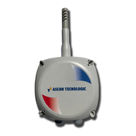
Ascon tecnologic H6 Series User manual

Ascon tecnologic

Ascon tecnologic H6 Series User manual

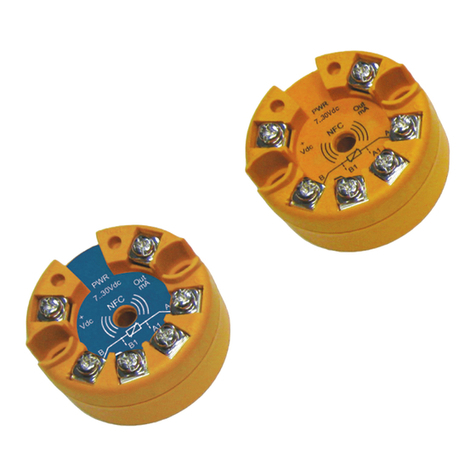
Ascon tecnologic ATT1 User manual

Ascon tecnologic

Ascon tecnologic ATT1 User manual

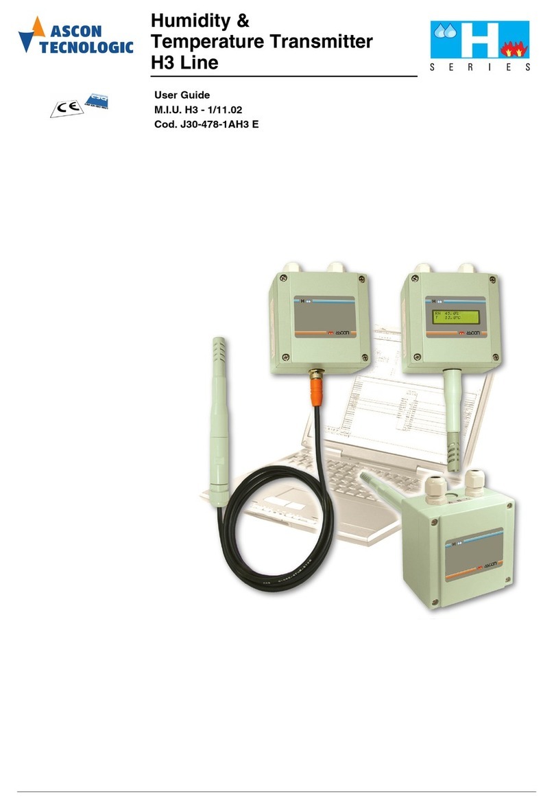
Ascon tecnologic H3 Line User manual

Ascon tecnologic

Ascon tecnologic H3 Line User manual

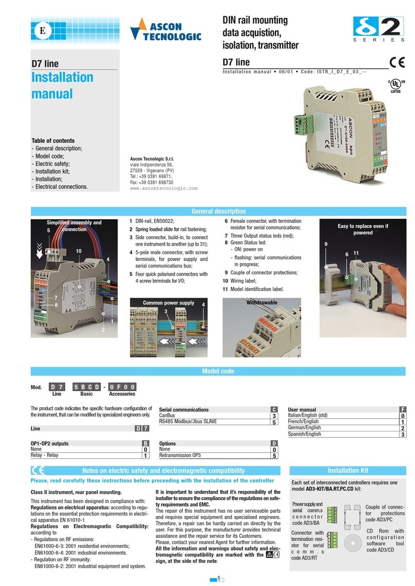
Ascon tecnologic D7 line User manual

Ascon tecnologic

Ascon tecnologic D7 line User manual

Ascon tecnologic ATT1 Installation and operation manual

Ascon tecnologic

Ascon tecnologic ATT1 Installation and operation manual

Popular Transmitter manuals by other brands

SDT T-Sonic1 user manual

SDT

SDT T-Sonic1 user manual

FlowLine EchoPod DL34 Series quick start

FlowLine

FlowLine EchoPod DL34 Series quick start

Sennheiser SK 1011 manual

Sennheiser

Sennheiser SK 1011 manual

Emerson Rosemount 6888A Reference manual

Emerson

Emerson Rosemount 6888A Reference manual

Lindy 38019 Quick installation guide

Lindy

Lindy 38019 Quick installation guide

ABB LST400 operating instructions

ABB

ABB LST400 operating instructions

MuxLab 500764-TX Quick installation guide

MuxLab

MuxLab 500764-TX Quick installation guide

evertz 7700 Series manual

evertz

evertz 7700 Series manual

KMC Controls TTE-1001 installation guide

KMC Controls

KMC Controls TTE-1001 installation guide

Siemens SITRANS F MASS 6000 Ex d operating instructions

Siemens

Siemens SITRANS F MASS 6000 Ex d operating instructions

Trust Start Series Important information

Trust

Trust Start Series Important information

Hoffer Flow Controls CAT3 user manual

Hoffer Flow Controls

Hoffer Flow Controls CAT3 user manual

Spatz HDMI-GIGALAN-TX user guide

Spatz

Spatz HDMI-GIGALAN-TX user guide

zisa ZS-TX1000 user guide

zisa

zisa ZS-TX1000 user guide

M-system CTS2 instruction manual

M-system

M-system CTS2 instruction manual

PR Elecronics PReasy 4116 manual

PR Elecronics

PR Elecronics PReasy 4116 manual

Jamara CCX Pro Instruction

Jamara

Jamara CCX Pro Instruction

DMP Electronics 1103 Series installation guide

DMP Electronics

DMP Electronics 1103 Series installation guide

manuals.online logo
manuals.online logoBrands
  • About & Mission
  • Contact us
  • Privacy Policy
  • Terms and Conditions

Copyright 2025 Manuals.Online. All Rights Reserved.