Ashcroft GC30 User manual

Product Information Page
All specifications are subject to change without notice.
All sales subject to standard terms and conditions.
© 2017 Ashcroft Inc.
ashcroft.com
info@ ashcroft.com
1.800.328.8258
Rev. A 02/17, Page 1 of 7
PIP #: TR-PI-103
Applicable to:
GC30
PROGRAMMING THE GC30 DIFFERENTIAL PRESSURE TRANSMITTER TO
MONITOR THE CLOGGING OF HVAC FILTER
The GC30 differential pressure transmitter is compact and flexible instrument
that supports many applications and is often used to monitor the clogging of
filters. It can be easily programmed to measure the pressure in IWC to monitor
and control the clogging on an HVAC filter.
Figure 1 - GC30 Differential Pressure Transmitter
Monitoring and Controlling HVAC Filter:
This illustration demonstrates the use of GC30 differential pressure transmitter to monitor the clogging
of an air filter. Most industrial filters have a pressure drop of 0.170 IWC with industry common practice
to replace filters when the pressure drop reaches 0.500 IWC to prevent unnecessary maintenance while
protecting the system from failing due to blockage. See principles of operation diagram below for
reference.
Figure 1 - Filter Monitoring Diagram
Air Flow
Air Flow
Air Filter

Product Information Page
All specifications are subject to change without notice.
All sales subject to standard terms and conditions.
© 2017 Ashcroft Inc.
ashcroft.com
info@ ashcroft.com
1.800.328.8258
Rev. A 02/17, Page 2 of 7
HVAC Filter Monitoring Application:
This example uses a GC30 differential pressure transmitter with 0 to 1.00 IWC range with two NPN
switches. The transmitter shall be programmed to activate the audible alarm when differential pressure
reaches 0.500 IWC with output 1 switch and to shut down the system if differential pressure reaches
0.750 IWC with output 2 switch by using external relays with normally open contacts for the audible
alarm and normally closed for the heating/cooling system. The outputs will reset at 0.200 IWC after the
filter is cleaned or replaced.
Installation:
Connect transmitter, relays, audible alarm and heating/cooling shutdown system per application,
diagrams below and manual instructions.
Figure 3 –Switch Schematic

Product Information Page
All specifications are subject to change without notice.
All sales subject to standard terms and conditions.
© 2017 Ashcroft Inc.
ashcroft.com
info@ ashcroft.com
1.800.328.8258
Rev. A 02/17, Page 3 of 7
GC30 Transmitter Output Switches Configuration Method:
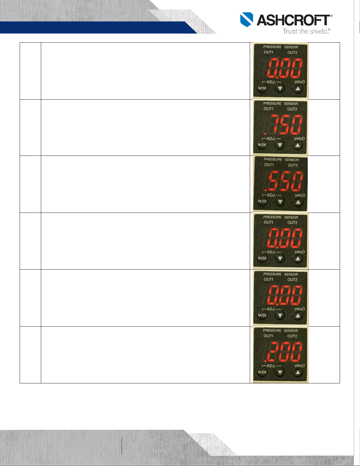
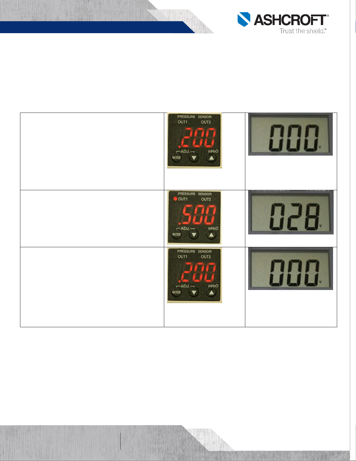
Method to program GC30 transmitter set points. Output 1 shall be set at .500 IWC to activate the
audible alarm, output 2 set at .750 IWC to shut down the heating/cooling system and both outputs shall
reset at .200 IWC by setting the hysteresis of output 1 at .300 IWC and output 2 at .550 IWC.
Press and hold MODE button for more than three seconds to get into
program mode.
Press UP or Down arrow to make changes.
Press and release MODE button to select changes and to walk through the
menu.
Continue to Step-1 after power-on message.
Press and hold MODE button for more than three seconds to return to
measuring mode.
Step
1
Press and hold MODE button for more than three seconds to get
into program mode.
CNP To select hysteresis (HYS) or Window comparator (yin).
Select HYS to enter switches set point, hysteresis, and ON OFF delay
time.
Press UP or Down arrow to display HYS.
Press and release MODE button to select and move to the next step.
Step
2
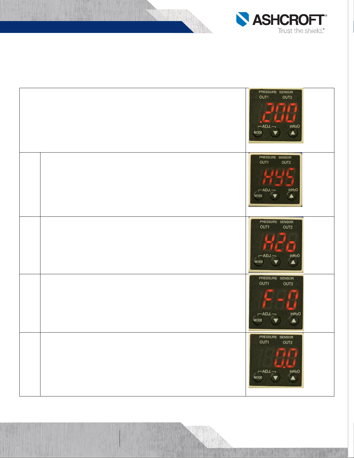
Uni To select units (H2O, mmHG, KPA or arbitrary units)
Press Up or Down arrow until H2o is displayed.
Press and release MODE button to select and move to the next step.
Step
3
FiL To enter filter selection, six filter selection options (F0 to F5).
Use the filter function to improve analog output and difficult to read
display if pressure oscillates.
Select factory default filter since pressure fluctuation is not
expected.
Press UP or Down arrow to display F0.
Press and release MODE button to select and move to the next step.
Step
4
A-L To enter analog output zero reference corresponding to 1 V
analog output.
This application does not use the analog output.
0.0 is displayed. That is the transmitter default analog output at 0%
FS (1 Vdc at .000 IWC).
Press and release MODE button to select and move to the next step.

Product Information Page
All specifications are subject to change without notice.
All sales subject to standard terms and conditions.
© 2017 Ashcroft Inc.
ashcroft.com
info@ ashcroft.com
1.800.328.8258
Rev. A 02/17, Page 4 of 7
Step
5
A-H To enter span analog output reference corresponding to 5 V
analog output.
This application does not use the analog output.
100.0 is displayed. That is the transmitter default analog output at
100% FS (5 V at 1.00 IWC).
Press and release MODE button to select and move to the next step.
GC30 Transmitter Switch Set Point and Dead Band Set Up Method:
Press and hold MODE button less than three seconds to get into program
mode.
Press UP or Down arrow to make changes.
Press and release MODE button to select changes and to move to the next
step.
Continue to Step-1 after once in program mode.
Press and hold MODE button for more than three seconds to return to
measuring mode.
Step
1
A-1 To enter output 1 switch audible alarm set point when
differential pressure reaches .500 IWC.
Press UP or Down until .500 is displayed.
Press and release MODE button to select and move to the next step.
Step
2
b-1 To enter output 1 switch dead band.
Set dead band to .300 IWC to deactivate switch at .200 IWC.
Press UP or Down until .300 is displayed.
Press and release MODE button to select and move to the next step.
Step
3
On1 To delay output 1 switch turn on.
Delay output 1 switch turn on shall not be used for this application.
Press Up or Down arrow until 0.00 is displayed.
Press and release MODE button to select and move to the next step.

Product Information Page
All specifications are subject to change without notice.
All sales subject to standard terms and conditions.
© 2017 Ashcroft Inc.
ashcroft.com
info@ ashcroft.com
1.800.328.8258
Rev. A 02/17, Page 5 of 7
Step
4
OF1 To delay output 1switch turn off.
Delay output 1 switch turn off shall not be used for this application.
Press Up or Down arrow until 0.00 is displayed.
Press and release MODE button to select and move to the next step.
Step
5
A-2 To enter output 2 switch shutdown set point .750 IWC.
Press UP or Down until .750 is displayed.
Press and release MODE button to select and move to the next step.
Step
6
b-1 To enter output 2 switch dead band.
Set dead band to .550 IWC to deactivate switch at .200 IWC.
Press UP or Down until .550 is displayed.
Press and release MODE button to select and move to the next step.
Step
7
On2 To delay output 2 switch turn on.
Delay output 2 switch turn on shall not be used for this application.
Press Up or Down arrow until 0.00 is displayed.
Press and release M button to select and move to the next step.
Step
8
OF2 To delay output 2 switch turn off.
Delay output 2 switch turn off shall not be used for this application.
Press Up or Down arrow until 0.00 is displayed.
Press and release MODE button to select and move to the next step.
Step
9
LoP Loop check mode allows program and switches verification with
the transmitter pressurized or non-pressurized. It simulates the
process and allows for troubleshooting.
Press Up or Down arrow to simulate pressure values.
After verification press and hold MODE button for more than three
seconds to return to measuring mode.

Product Information Page
All specifications are subject to change without notice.
All sales subject to standard terms and conditions.
© 2017 Ashcroft Inc.
ashcroft.com
info@ ashcroft.com
1.800.328.8258
Rev. A 02/17, Page 6 of 7
Switching Verification:
Ensure switches wiring per figure 3 diagram or installation and maintenance instructions. Switching
verification can be tested during measurement mode or loop check. Change loop check value or apply
equivalent pressure (see results below for reference).
Output 1 Switch Set Point to Activate Audible Alarm When Differential Pressure Reaches .500 IWC
For test purpose a 290 ohms resistor shall
be used as the switch load (wire switch per
manual instructions or figure above).
Press the Up or Down arrow until .200 is
displayed or apply .200 IWC.
Output 1 switch in normal state (OFF).
Place voltmeter leads across resistor and
verify voltage reading (0 V dc).
Press the Up arrow until .500 is displayed or
increase pressure to .500 IWC.
Output 1 switch turns ON.
Verify voltmeter reading (28 VDC).
External relay energizes.
Relay normally open closes
Audible alarm turns ON.
Press the Down arrow until .200 is displayed
or decrease pressure to .200 IWC.
Verify voltage reading (0 V dc).
Output 1 switch changes to normal state
(OFF).
Audible alarm turns OFF.

Product Information Page
All specifications are subject to change without notice.
All sales subject to standard terms and conditions.
© 2017 Ashcroft Inc.
ashcroft.com
info@ ashcroft.com
1.800.328.8258
Rev. A 02/17, Page 7 of 7
Output 2 Switch Set Point to Shut Down Heating/Cooling System When Differential Pressure Reaches
0.750 IWC
For test purpose a 290 ohms resistor shall
be used as the switch load (wire switch per
manual instructions or figure above).
Press the Up or Down arrow until .200 is
displayed or apply .200 IWC.
Output 2 switch in normal state (OFF).
Place voltmeter leads across resistor and
verify voltage reading (0 V dc).
Press the Up arrow until .750 is displayed or
increase pressure up to .750 IWC.
Output 2 switch turns ON (Out 1 is ON since
differential pressure reached .500 IWC).
Verify voltmeter reading (28 VDC).
External relay energizes.
Relay normally closed switch opens,
heating/cooling system shuts down.
Press the Down arrow until .200 is displayed
or decrease pressure to .200 IWC.
Verify voltage reading (0 V dc).
Switch changes to normal state (OFF).
Other manuals for GC30
1
Table of contents
Other Ashcroft Accessories manuals