pema
architect & engineering SpecS
Pema8125
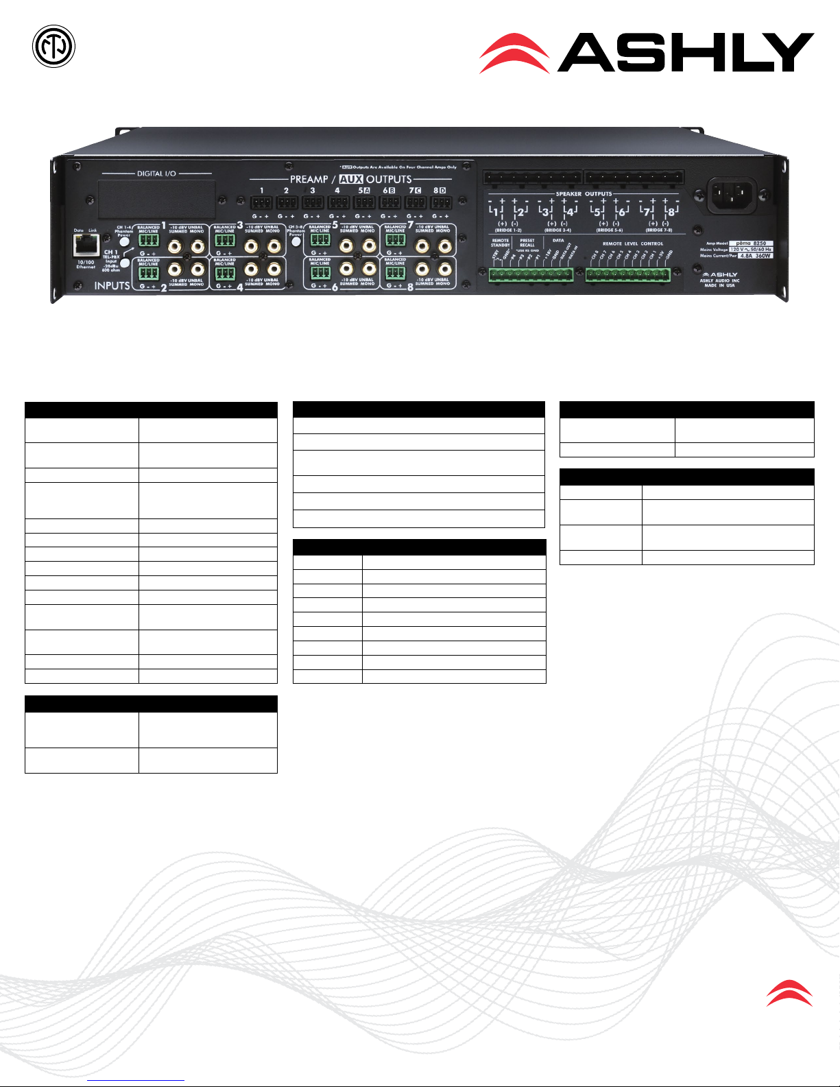
The powered digital signal processor shall consist of eight inputs and eight power amplier outputs with the ability to assign any input to any output. Each input channel shall include a summed stereo (RCA, +11dB
maximum) and mic/line gain stage (3-pin Euroblock, +21dB maximum) capable of 0, +20dB, +40dB, and +60dB of gain with +15V phantom power when selected. Summed stereo input impedance shall be 3.16k Ohms
unbalanced and mic/line input impedance shall be 4.8k Ohms acve balanced. Channel One shall include a transformer-isolated TEL-PBX select. Each input and output shall have individual mute capability. Each input
and output shall have six processing blocks congurable for Dynamics (ambient noise compensaon, compressor/limiter, auto-leveler, ducker, gate), Gain (including Group VCA and remote gain), Equalizaon (31-band
graphic, parametric x 10, feedback suppressor), Crossover, Delay, Metering, and Signal Generator (sine wave, pink noise, white noise). The roung stage shall allow the user to assign an input to any or a combinaon
of outputs and separately adjust how much signal level goes to each output (matrix mixer). The matrix mixer shall also have selectable gain-sharing automac mixing capability. Each input stage shall have an addion-
al preamp output (post DSP) on the back panel (3-pin Euroblock). Eight powered outputs shall deliver 75W @ 8 Ohms, 125W @ 4 Ohms (7.62mm Euroblock), and channel pairs can be bridged for 250W @ 8 Ohms.
Frequency response shall be ±1dB 20Hz to 20kHz. Signal-to-Noise shall be greater than 102dB, 20Hz – 20kHz unweighted. LED indicators shall show signal level (-18, -12, -6), clip/mute, bridge, over temperature and
over current condions. Output levels shall be adjusted by front panel volume controls when enabled. Full programming and control of the unit shall be from the rear panel RJ-45 jack connected to a 10/100BASE-T
Ethernet LAN connected to a PC running Ashly’s Protea NE Soware. Thirty internal presets (scenes) shall be standard and four scenes shall be accessible via contact closure. The powered digital processor shall have
Cobranet and Dante factory opon. A back panel contact closure shall place the unit in “Standby” reducing power consumpon when idle. The power switch shall be enabled or disabled as needed. Five password
user names and eight levels of security shall be available. A temperature dependent speed-controlled axial fan shall maintain the correct operang temperature. The unit shall weigh 20 lbs net and mount in a stan-
dard 19” rack using 2 spaces (3.5” high).
The powered digital processor shall be an Ashly PEMA Protea Equipped Media Amplier model pema8125
Pema8250
The powered digital signal processor shall consist of eight inputs and eight power amplier outputs with the ability to assign any input to any output. Each input channel shall include a summed stereo (RCA, +11dB
maximum) and mic/line gain stage (3-pin Euroblock, +21dB maximum) capable of 0, +20dB, +40dB, and +60dB of gain with +15V phantom power when selected. Summed stereo input impedance shall be 3.16k Ohms
unbalanced and mic/line input impedance shall be 4.8k Ohms acve balanced. Channel One shall include a transformer-isolated TEL-PBX select. Each input and output shall have individual mute capability. Each input
and output shall have six processing blocks congurable for Dynamics (ambient noise compensaon, compressor/limiter, auto-leveler, ducker, gate), Gain (including Group VCA and remote gain), Equalizaon (31-band
graphic, parametric x 10, feedback suppressor), Crossover, Delay, Metering, and Signal Generator (sine wave, pink noise, white noise). The roung stage shall allow the user to assign an input to any or a combinaon
of outputs and separately adjust how much signal level goes to each output (matrix mixer). The matrix mixer shall also have selectable gain-sharing automac mixing capability. Each input stage shall have an addion-
al preamp output (post DSP) on the back panel (3-pin Euroblock). Eight powered outputs shall deliver 150W @ 8 Ohms, 250W @ 4 Ohms (7.62mm Euroblock), and channel pairs can be bridged for 500W @ 8 Ohms.
Frequency response shall be ±1dB 20Hz to 20kHz. Signal-to-Noise shall be greater than 102dB, 20Hz – 20kHz unweighted. LED indicators shall show signal level (-18, -12, -6), clip/mute, bridge, over temperature and
over current condions. Output levels shall be adjusted by front panel volume controls when enabled. Full programming and control of the unit shall be from the rear panel RJ-45 jack connected to a 10/100BASE-T
Ethernet LAN connected to a PC running Ashly’s Protea NE Soware. Thirty internal presets (scenes) shall be standard and four scenes shall be accessible via contact closure. The powered digital processor shall have
Cobranet and Dante factory opon. A back panel contact closure shall place the unit in “Standby” reducing power consumpon when idle. The power switch shall be enabled or disabled as needed. Five password
user names and eight levels of security shall be available. A temperature dependent speed-controlled axial fan shall maintain the correct operang temperature. The unit shall weigh 20 lbs net and mount in a stan-
dard 19” rack using 2 spaces (3.5” high).
The powered digital processor shall be an Ashly PEMA Protea Equipped Media Amplier model pema8250
Pema8125.70
The powered digital signal processor shall consist of eight inputs and eight power amplier outputs with the ability to assign any input to any output. Each input channel shall include a summed stereo (RCA, +11dB
maximum) and mic/line gain stage (3-pin Euroblock, +21dB maximum) capable of 0, +20dB, +40dB, and +60dB of gain with +15V phantom power when selected. Summed stereo input impedance shall be 3.16k Ohms
unbalanced and mic/line input impedance shall be 4.8k Ohms acve balanced. Channel One shall include a transformer-isolated TEL-PBX select. Each input and output shall have individual mute capability. Each input
and output shall have six processing blocks congurable for Dynamics (ambient noise compensaon, compressor/limiter, auto-leveler, ducker, gate), Gain (including Group VCA and remote gain), Equalizaon (31-band
graphic, parametric x 10, feedback suppressor), Crossover, Delay, Metering, and Signal Generator (sine wave, pink noise, white noise). The roung stage shall allow the user to assign an input to any or a combinaon
of outputs and separately adjust how much signal level goes to each output (matrix mixer). The matrix mixer shall also have selectable gain-sharing automac mixing capability. Each input stage shall have an addion-
al preamp output (post DSP) on the back panel (3-pin Euroblock). Eight powered outputs shall deliver 125W @ 70V (7.62mm Euroblock), and channel pairs can be bridged for 250W @ 240V. Frequency response shall
be ±1dB 20Hz to 20kHz. Signal-to-Noise shall be greater than 102dB, 20Hz – 20kHz unweighted. LED indicators shall show signal level (-18, -12, -6), clip/mute, bridge, over temperature and over current condions.
Output levels shall be adjusted by front panel volume controls when enabled. Full programming and control of the unit shall be from the rear panel RJ-45 jack connected to a 10/100BASE-T Ethernet LAN connected
to a PC running Ashly’s Protea NE Soware. Thirty internal presets (scenes) shall be standard and four scenes shall be accessible via contact closure. The powered digital processor shall have Cobranet and Dante
factory opon. A back panel contact closure shall place the unit in “Standby” reducing power consumpon when idle. The power switch shall be enabled or disabled as needed. Five password user names and
eight levels of security shall be available. A temperature dependent speed-controlled axial fan shall maintain the correct operang temperature. The unit shall weigh 20 lbs net and mount in a standard 19” rack
using 2 spaces (3.5” high).
The powered digital processor shall be an Ashly PEMA Protea Equipped Media Amplier model pema8125.70
Pema8250.70
The powered digital signal processor shall consist of eight inputs and eight power amplier outputs with the ability to assign any input to any output. Each input channel shall include a summed stereo (RCA, +11dB
maximum) and mic/line gain stage (3-pin Euroblock, +21dB maximum) capable of 0, +20dB, +40dB, and +60dB of gain with +15V phantom power when selected. Summed stereo input impedance shall be 3.16k Ohms
unbalanced and mic/line input impedance shall be 4.8k Ohms acve balanced. Channel One shall include a transformer-isolated TEL-PBX select. Each input and output shall have individual mute capability. Each input
and output shall have six processing blocks congurable for Dynamics (ambient noise compensaon, compressor/limiter, auto-leveler, ducker, gate), Gain (including Group VCA and remote gain), Equalizaon (31-band
graphic, parametric x 10, feedback suppressor), Crossover, Delay, Metering, and Signal Generator (sine wave, pink noise, white noise). The roung stage shall allow the user to assign an input to any or a combinaon
of outputs and separately adjust how much signal level goes to each output (matrix mixer). The matrix mixer shall also have selectable gain-sharing automac mixing capability. Each input stage shall have an addion-
al preamp output (post DSP) on the back panel (3-pin Euroblock). Eight powered outputs shall deliver 250W @ 70V (7.62mm Euroblock), and channel pairs can be bridged for 500W @ 70V. Frequency response shall
be ±1dB 20Hz to 20kHz. Signal-to-Noise shall be greater than 102dB, 20Hz – 20kHz unweighted. LED indicators shall show signal level (-18, -12, -6), clip/mute, bridge, over temperature and over current condions.
Output levels shall be adjusted by front panel volume controls when enabled. Full programming and control of the unit shall be from the rear panel RJ-45 jack connected to a 10/100BASE-T Ethernet LAN connected
to a PC running Ashly’s Protea NE Soware. Thirty internal presets (scenes) shall be standard and four scenes shall be accessible via contact closure. The powered digital processor shall have Cobranet and Dante
factory opon. A back panel contact closure shall place the unit in “Standby” reducing power consumpon when idle. The power switch shall be enabled or disabled as needed. Five password user names and
eight levels of security shall be available. A temperature dependent speed-controlled axial fan shall maintain the correct operang temperature. The unit shall weigh 20 lbs net and mount in a standard 19” rack
using 2 spaces (3.5” high).
The powered digital processor shall be an Ashly PEMA Protea Equipped Media Amplier model pema8250.70