Asian Phoenix Resources MHG-T8 Quick reference guide

Use and Care
Instructions
for your new
T8 & T16 Turgo
Micro-hydroelectric Generator
Models: MHG-T8
MHG-T16
Asian Phoenix Resources Ltd., Canada

READ THIS FIRST
This manual contains important information concerning your new PowerPal T8 or
T16 Turgo micro-hydroelectric generator. It covers Models MHG-T8 and MHG-T16.
You should read this manual carefully before installing PowerPal or allow a trained
technician from your local PowerPal Service Center to install it for you.
Your PowerPal generator is designed to be simple to operate and easy to maintain. If
used in accordance with these instructions your PowerPal will give you many years of
service. PowerPal is also designed with safety in mind, but any electric device can be
dangerous if not used correctly. At several points in this manual, instructions
requiring special attention that must be followed are shown as:
SAFETY FIRST
•Never allow electrical contacts to become wet. Beware of electrocution.
•Never attempt to cut electrical wires or open appliances for repair if the generator
is working. Unplug the main cable first.
•Inform children of the dangers of electrocution. Never allow them to play with
electrical connections.
•Keep fingers away from the moving turbine runner.
•If you have any questions about safety, please ask your PowerPal Service Center.
•Product must be earth bonded (grounded).
OPERATING CAUTIONS
•Under conditions of higher water heads than given for each model in this manual,
PowerPal is able to generate higher power outputs than rated. This can also occur
if the intake pipe diameter exceeds the recommended diameter. If maximum
power consumption listed in this manual is exceeded then the PowerPal generator
may be irrepairably damaged and require total rewiring. See the section on
‘Technical Specifications’.
•Do not forget to grease the bearings at the recommended times. Failure to do this
will result in excessive wear on the bearings and shorten their life.
•Always ensure that the Electronic Load Controller is set at approximately 220V.
Otherwise, the life of lights and appliances may be reduced.
Warning symbol - beware of hazards or unsafe practices that may cause
injury or death.
Caution symbol – beware of hazards or unsafe practices that may damage the
product.
While electricity improves your life, it can also be dangerous if simple
precautions are not followed:
Your PowerPal generator is designed for simple operation and low
maintenance. However, the following operating cautions must be followed to
ensure a long life for PowerPal:
PowerPal™T8 & T16 Turgo 2

POWERPAL COMPONENTS
Inside your PowerPal box you will find:
•1 x generator-turbine assembly
•1 x penstock adaptor flange
•1 x gate valve
•1 x rubber gasket
•6 x M24 foundation nuts and bolts
•1 x control panel including electronic load controller
•2 x ballast load elements
•1 x Guarantee Card
•1 x this instruction manual.
Please advise immediately if any parts are missing. Complete your Guarantee Card
and have it signed by your PowerPal dealer.
The PowerPal system consists of two major components – a hydroelectric generator
and an electronic load controller. Other components are necessary and these can be
purchased locally. The penstock (intake pipe) should be made from steel. Your
PowerPal dealer can advise you about this.
Therefore, other parts which are not included in the box but which are required to
make PowerPal work are:
•a 28m – 40m length of 4mm steel pipe with internal diameter 150mm.
•electrical wire from generator to house. See the section on ‘Technical
Specifications’ for the correct wire size.
•household wiring.
These are available from your dealer or local electrical store.
SYSTEM DIAGRAM
The following diagram shows how the non-electrical components fit together. Further
reading of this manual will provide the necessary explanations. Additional drawings
are found in Appendix A.
PowerPal™T8 & T16 Turgo 3

PowerPal™T8 & T16 Turgo 4
A. Forebay, or water tank
B. Atmospheric vent
C. Penstock, or intake pipe
D. Gate valve
E. Spear valve
F. Generator
G. Turbine
H. Turbine stand
Dimensions are in mm.
A
C
E
GF
H
Forebay dimensions
B
D

SELECTING A SITE
PowerPal is designed for use in a wide range of locations. There are two critical
factors that influence power output – head and flow. Head is the vertical distance
between the turbine and the water source (forebay), measured in meters. Flow is the
amount of water that passes through the turbine at any instant, measured in litres per
second (l/sec). The following table shows the various combinations of head and flow
to achieve certain maximum power outputs for each model:
For example, if your site has available 24 meters of head and a water flow of 33.3
litres per second then a PowerPal MHG-T8 will produce up to 4.7kW of electricity.
Measuring Head
The net head is the vertical height from where the water flow enters the penstock
down to the level of the turbine. It is shown in the System Diagram. To measure this,
use a tape measure and a clinometer or spirit level etc. A less accurate but useful
alternative is to make your own level from a transparent tube half-filled with water.
Attach this to the top of a 1m long stick and then point this horizontally at a point
further up the slope as though it were a spirit level. By going to that point and
repeating the process the total head can be measured – see the drawing below.
Another method is to use an accurate pressure gauge and a length of hose. Run a
water-filled hose from the forebay to the turbine site and attach the pressure gauge to
the bottom end. The pressure gauge shows 1.422 psi / meter of head e.g. 34 psi for a
head of 24m to 48 psi for a head of 34m.
This head should be between 24 and 34 meters for both the MHG-T8 model and the
MHG-T16 model. If it is smaller then the power output will be reduced. If it is larger
then your power output will be increased. While increased power output appears
MHG-T8 MHG-T16
Water head H (m)
24m
26m
28m
30m
32m
34m
24m
26m
28m
30m
32m
34m
Water flow Q (l/sec.)
33.3
34.6
36.0
37.2
38.4
39.6
66.6
69.2
72.0
74.4
76.8
79.2
Turbine output (kW)
5.9
6.6
7.4
8.2
9.0
10.0
11.8
13.2
14.8
16.4
18.0
20.0
Gen. output (kW)
4.7
5.3
5.9
6.6
7.2
8.0
9.4
10.6
11.8
13.1
14.4
16.0
10m
9
8
7
6
5
4
3
2
1
0m
Measuring Head:
Walk up the slope from where you wish to place
the turbine to where the water source is. Or, do
the reverse: walk down the slope from the water
source to locate the best site for the turbine.
PowerPal™T8 & T16 Turgo 5

desirable, if the head is too large then the rotor will turn too fast and reduce the life of
the bearings.
Measuring Flow
While the range of head for both T8 and T16 models is the same, the main difference
between them is one of water flow. For flows less than 66 l/sec a MHG-T8 is required
and for flows greater than 40 l/sec the MHG-T16 is recommended.
The best way to measure the water flow is to use the ‘weir method’, which is beyond
the scope of this manual. Your PowerPal dealer should be able to advise you about
flow measurement otherwise contact the manufacturer. Another method is the
‘container method’. Take a piece of pipe the same diameter as the penstock, insert it
in the stream or dam where the flow is expected to come from, and measure the flow
from there.
In the diagram below, a short length of pipe (less than 1 meter) is buried into the side
of a small ‘dam’ using mud or improvised sandbags. The top end of the pipe is
completely submerged and part of the normal stream flow is diverted through the
pipe. When this is flowing smoothly, a bucket of known volume is quickly placed to
collect this flow and the time it takes to fill the bucket is recorded. The ideal bucket
size would be 100 or 200 litres (half or a whole empty oil drum). Divide the volume
of the bucket (in litres) by the time it takes to fill the bucket (in seconds) to get the
approximate flow rate in litres per second.
SITE PREPARATION
Once the correct head and flow have been located then the length and position of the
penstock can be determined. While vertical head is important, the horizontal slope and
penstock length may vary although penstock inclination should be >60°.
Do not attempt to exceed the recommended head height.
Measuring Flow:
Flow = volume of bucket (litres)
time to fill bucket (seconds)
PowerPal™T8 & T16 Turgo 6

The penstock should be made of steel with internal diameter of 150mm and thickness
4mm. The gate valve (included) must be installed at the high-pressure end of the
penstock for closing whenever servicing the turbine.
A good way to reduce penstock length is shown in the following diagram.
When installing the penstock, try to keep it as straight as possible and avoid sharp
turns or angles. To do this, part of the hillslope may need excavating while in other
places the penstock may need supporting with poles etc. Steeper terrain has advan-
tages over more gentle terrain as cost is reduced by the use of a shorter penstock.
The forebay, or water holding tank at the top of the penstock is designed to contain a
water volume of approximately 2.5x the volume of water in the penstock i.e. 1750
litres. Dimensions of the ideal design are shown in the system diagram although the
main point is to ensure that the forebay won’t become empty.
The penstock is shown by the black line
A-B. In the first diagram (A) the penstock
follows the stream. This may lead to
unnecessary length and cost. In diagram
B, the most direct route is selected to
reduce length and cost. Diagram C shows
the best alternative where a side channel
or ‘power conduit’ is cut into the side of
the hill. This carries the water to a point
as close to above the turbine as possible
and best reduces the length of penstock
required.
The power conduit roughly follows the
hill’s contour and need only be a simple
ditch say 30cm x 30cm in section.
B
A
C
PowerPal™T8 & T16 Turgo 7

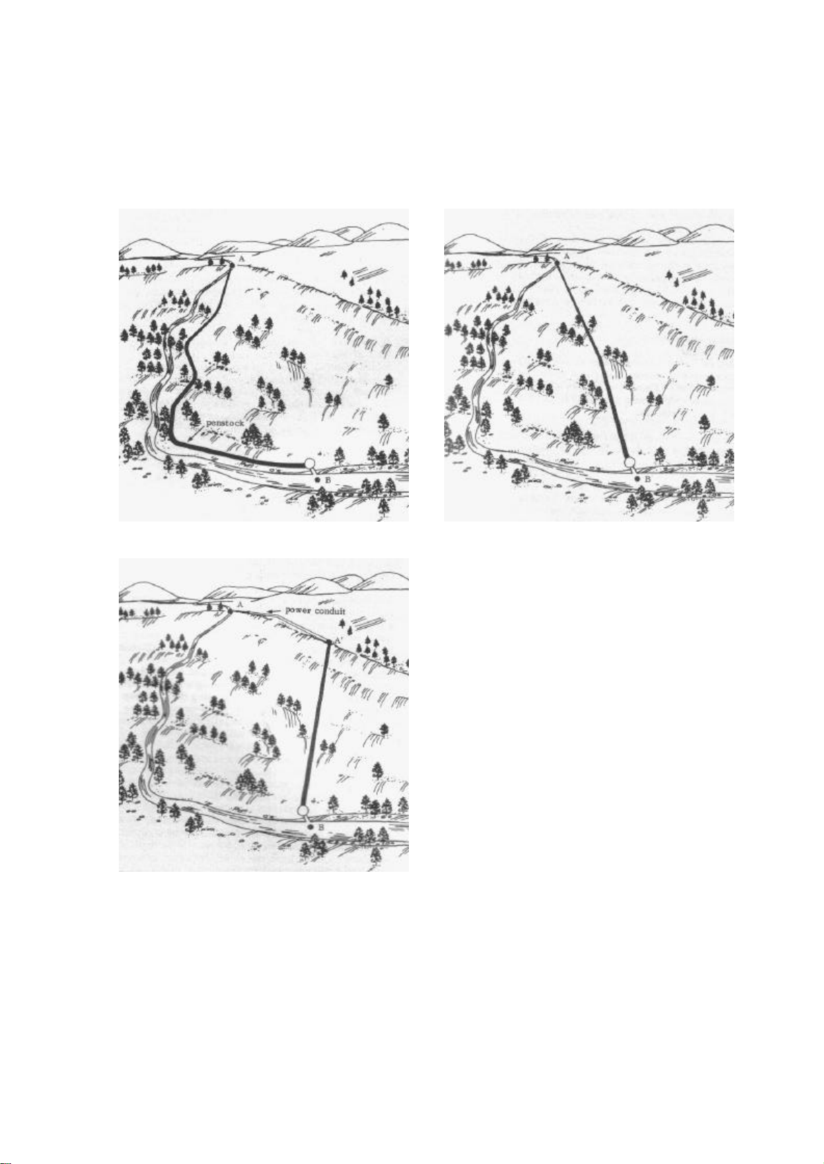
The top of the penstock is typically placed not at the bottom but some way up the
forebay wall so that the bottom of the forebay acts as a sink for rotting leaf litter,
deposited sand and mud etc. This sink may need periodic cleaning out. Another good
idea is to cover the end of the penstock with a piece of wire mesh (debris screen) to
keep leaves etc. from flowing in and clogging the turbine. See Appendix B for the
ideal forebay design.
SYSTEM INSTALLATION
Mechanical Aspects
After locating a suitable site and completing the civil works, your PowerPal is ready
for installation. To do this:
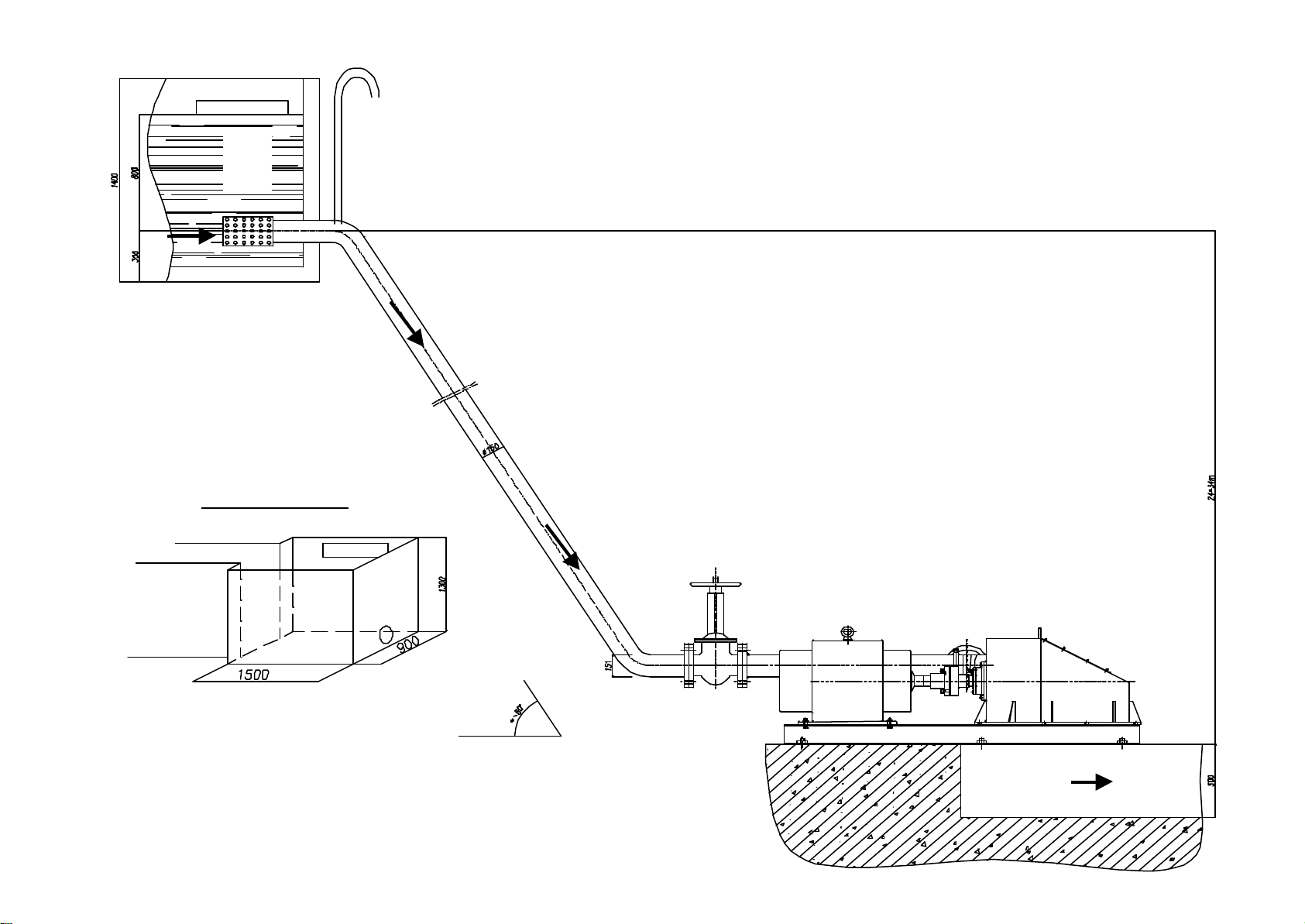
1. Bolt the turbine to a turbine stand or base which allows at least 500mm clearance
between the turbine and the ground. This clearance is required to prevent
splashback that will disrupt turbine performance. The turbine stand should be
made from concrete with the six M24 foundation bolts embedded.
2. Attach the gate valve to the nozzle injector pipe followed by a ~120° elbow bend
which will connect to the penstock. The angle will depend on the site slope.
3. Affix a 120° (or other) elbow bend into the forebay wall. This should be fitted
with an atmospheric vent (hollow bent pipe), which allows air to escape from the
penstock. The upper opening of the atmospheric vent should be higher than the
water level in the forebay. Divert water away from the forebay or else block the
top of the penstock pipe during the installation procedure.
4. Start installing the penstock. Assembly can begin from either direction. The
penstock should be well secured i.e. supported or buried at regular intervals to
support its weight when full – this is particularly important at the bottom of the
penstock so that PowerPal cannot be knocked over. Several people may be
required to install the penstock until it is fitted into both elbow bends.
Electrical Aspects
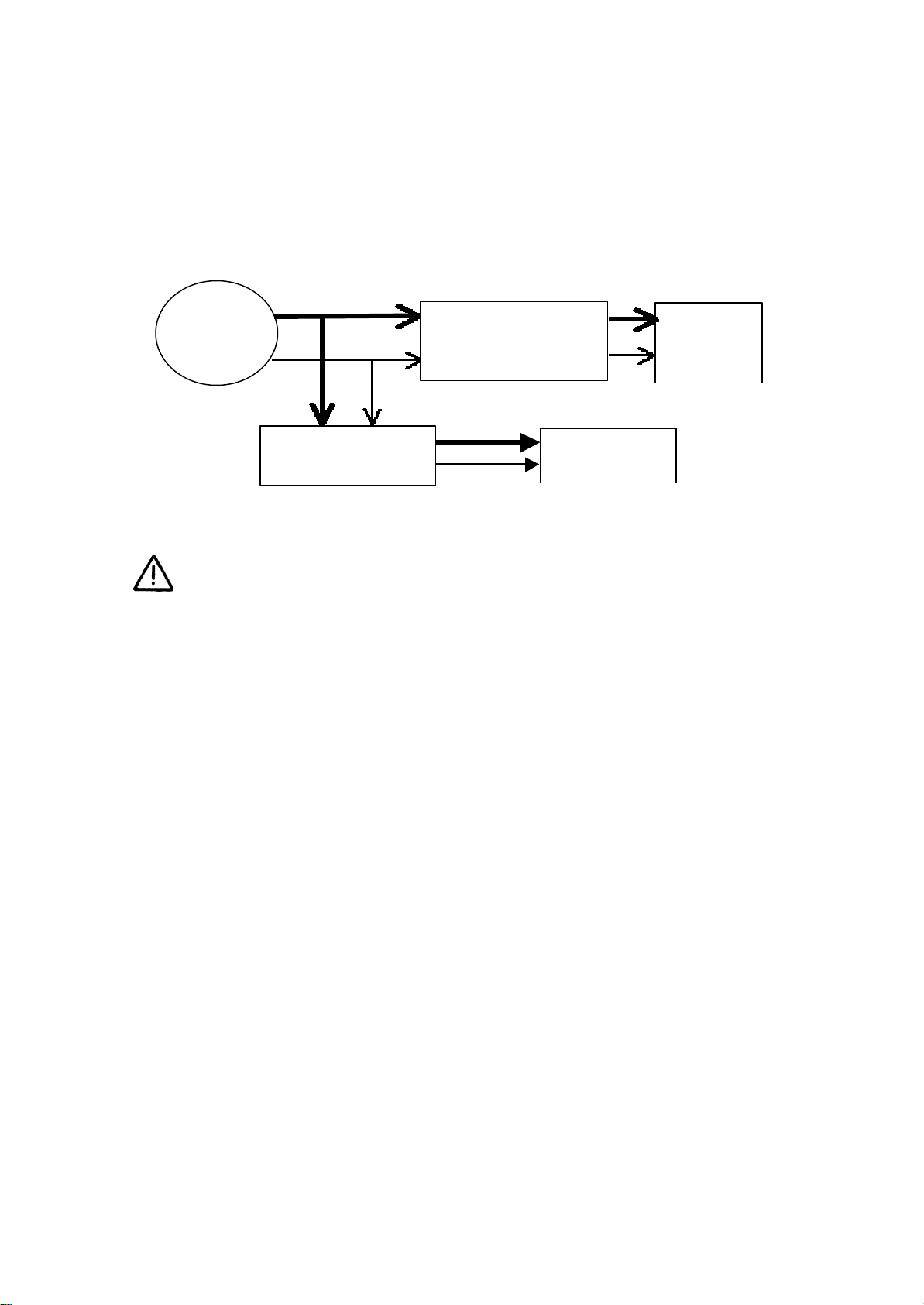
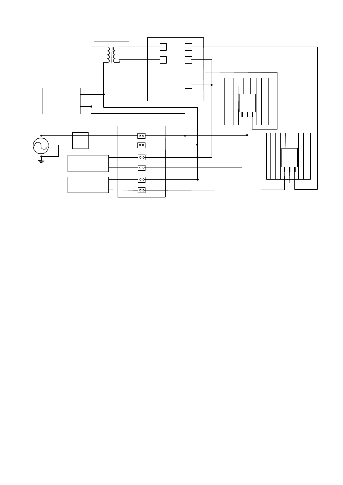
The generator is of permanent magnet, synchronous type. Load is controlled by an
electronic load controller (ELC) which is installed as part of the control box. The ELC
is designed to maintain constant voltage and near-constant frequency by keeping a
constant electric load on the generator. To do this, the ELC switches any power not
being used by the consumer to air-heating ballast loads (supplied) where the surplus
energy is burnt off as heat.
Two ballast loads are supplied, one main and one supplementary. The main ballast
load accounts for 66% of the total while the supplementary ballast load account for
33%. Although optional, the supplementary ballast allows the generator to run at a
lower temperature. The wave form distortion caused by switching off the triac or
thyristors causes the generator to run hot. This can be reduced by having part of the
ballast load switched to zero so that the voltage across the ballast gives a good
PowerPal™T8 & T16 Turgo 8

waveform. This is where the supplementary ballast is used. If the power dissipated in
the main ballast is over a certain limit then the additional ballast is automatically
switched on and when its power drops below a certain limit it automatically switches
off.
The ELC is wired in parallel with the generator output so that it can’t be inadvertantly
switched out of the circuit. The system is connected as follows:
To connect the electrical components, please follow these steps:
1. Install the control box in a convenient location that is protected from rain and sun.
This may be either in a powerhouse along with the turbine or else in a house at the
user’s end.
2. Earth-bond (ground) PowerPal. Do this by attaching one end of a suitable length
of 16mm2wire to PowerPal and the other end to a metal object or metal stake in
the ground nearby PowerPal.
3. Connect the generator to the control box. All wiring from the generator to the
control box, from the control box to the user load and from the control box to the
ballast load should be done using insulated multistrand copper wire, the size of
which is given in the Technical Specifications part of this manual.
The following wiring diagram shows the location of all connection points but note
that most components are already wired and installed within the control panel.
The electrics should be installed by persons competent in mains voltage
wiring. This system operates on a switched neutral basis. Neutral and phase
connections to the load elements should be treated as live at all times!
hydro
turbine Main network or house
distribution board
Electronic Load
Controller - ELC Ballast load(s)
220VAC
house supply
PowerPal™T8 & T16 Turgo 9

4. Connect the user load cables L1 and L2 between the control box and the house.
5. Connect the main and supplementary ballast loads to the control box as shown.
The combined (total) ballast load is rated 10-15% (maximum) higher than the
rated power output of the generator e.g. 11kW or 12kW for a 10kW generator.
The main ballast load will be approximately 7kW or 8kW (approx. 66%) while the
supplementary ballast load will be approximately 3kW or 4kW (approx. 33%).
The ballast loads will become hot, up to 100°C. To prevent injury and the risk of
fire, they must be installed in a safe place and preferably in an additional
enclosure.
6. Close the control box door. The system is now ready for its first operation.
OPERATION
1. Check that the power conduit and forebay are free of debris.
2. Ensure that the turbine is shut down and that all supply lines are electrically dead.
The switch on the door of the control box must be in the ‘off’ position.
3. Fully open both the spear valve and gate valve. The gate valve is always opened
when the turbine is operating and is only closed when servicing or repairing the
turbine.
4. Fill the forebay and allow the water to flow freely into the penstock. The turbine
runner will rotate and spent water will flow out in front of the turbine stand (into
an escape drain). Once the water is flowing freely the electrical testing may begin.
L2
L1
1 1
1
ELC single phase- 20kW
Pin
1
Transformer
Generator AC
240V ~ Pin
3
Pin
24 V ~ 1
Pin
41
Pin
1
Pin
go to Triac 1
go to Triac 2
neutral to main ballast load
neutral
Connector
METERS
line
line to main ballast load
1 2
3 4
5 6
7 8
9 10
11 12
neutral to supp. ballast load
line to supp. ballast load
Supplementary
ballast load
Main ballast
load
T1 T2 G
Heatsink
BTA26
600B
TRIAC 2
T1 T2 G
Heatsink
BTA26
600B
TRIAC 1
Main network or
house
distribution
board
PowerPal™T8 & T16 Turgo 10

5. As the water flow starts to create electric power, the voltage will rise until the
voltmeter on the control box reads 230V. If the voltage continues to rise, adjust
the water flow with the spear valve so that the voltage stays at 230V. The voltage
will then fall to 220V after a minute or two.
6. Operate like this for 15 minutes while observing any unusual noise, excessive
temperature or other problems and if OK then use the switch on the control panel
door to switch on the power to the user. Up till now the ballast load has been
receiving all the power and should be hot, but once switching on the user load the
power to the ballast load will fall.
7. The voltage should remain stable as loads are switched on or off. If the voltage
falls below 220V then check the water flow conditions. The voltage may need to
be checked and adjusted if the water flow rate changes e.g. a prolonged dry period
may gradually reduce it.
8. Whenever shutting down the system, first close the spear valve to reduce the flow
rate and once the voltmeter shows 100V, switch the control box to the ‘off’
position. Then slowly close the spear valve and then gate valve fully to stop the
system.
CARE AND MAINTENANCE
General care for your PowerPal will enhance its life. Following the instructions in this
manual is important.
Install PowerPal in a place that is unlikely to be flooded. A simple shelter with a roof
is required to protect the generator from rain or else a small shed can be built and
locked (preferable). If the inside of the generator assembly does become wet it will
require drying. No permanent damage will result, but check the bearings to see if they
have collected water. Do not try to dry it near a fire. Before using again, make sure
that the power socket is also dry. Condensation inside the generator is normal in
tropical areas and will not effect the performance of PowerPal, which is ‘tropicalized’.
Greasing the Bearings
PowerPal has two bearings in the turbine that require periodic attention – one near the
runner inside the turbine casing and the other where the turbine shaft attaches to the
generator. Both have been greased in the factory ready for use but require re-greasing
Do not plug appliances directly into PowerPal without using the load
controller. Incorrect voltage may result, which can damage your appliance.
Do not allow electrical contacts to become wet. Use dry hands. Beware of
electrocution.
Always turn the valve handles slowly and smoothly to avoid sudden changes
to water pressure in the penstock. Sudden changes can cause a ‘water
hammer’ effect and rupture the penstock.
PowerPal™T8 & T16 Turgo 11

every 3 months of continuous use. To do this, clean the nipples and apply extra grease
with a grease gun. The turbine should be stopped prior to greasing. The generator
bearings are maintenance-free.
Changing the Bearings and Seal
Apart from greasing the bearing, there are only two tasks that must be completed at
regular intervals. These are the changing of both turbine bearings and the bearing seal
every two years. See the section on Technical Specifications at the end of this manual
for part numbers. These are commonly available in most countries but if in doubt
contact your dealer.
To replace the bearings and seal, follow these steps:
1. Shut down the electrical system.
2. Slowly close the gate valve to stop the water supply to the turbine.
3. Disconnect the power cable at the generator.
4. Wait until little or no water flows out of the turbine and the runner stops rotating.
5. Disconnect the direct coupling between the turbine shaft and generator shaft.
6. Disconnect the runner from the turbine shaft.
7. Disconnect the bearing near the runner by pulling the turbine shaft towards the
generator.
8. Disconnect the bearing near the generator by pulling the turbine shaft towards the
turbine.
9. To replace the bearing seal, push it out of the bearing casing with a small steel
rod.
10. When reassembling, make sure that all parts are correctly in place and that all
bolts are tightened.
11. Slowly reopen the gate valve until normal water flow resumes. Wait until this
occurs before reconnecting the cable and restarting the system.
TROUBLESHOOTING
If any problems are encountered, check this section before contacting your Service
Center.
1. Head and flow conditions appear to be OK, but PowerPal will not work.
It is likely that the system has been installed incorrectly. Check this by following the
steps once more.
2. PowerPal has provided electricity for a while and suddenly the electricity stops.
Failure to grease the bearings on
time will shorten their life and
require their replacement. The
increased friction will also reduce
power output. Always clean the
nipple before greasing.
PowerPal™T8 & T16 Turgo 12

If this instruction manual is not followed and power consumption is too high, or if
there is a short circuit in an appliance the fuse in the electronic load controller will
break. This will stop the electric current. It is important to replace this fuse with
another of the same size (see Technical Specifications below). If the fuse breaks and
an oversize fuse is inserted then the generator windings may be damaged in the future.
If that happens the generator will need rewiring by an experienced motor rewinder.
3. Voltage is 220V under zero-load conditions but falls when a load is applied.
Excessive load has been applied. Reduce the load consumption to see if voltage
stabilizes and if not have the control box examined by a competent electrician.
4. Testing in the stream showed thatPowerPal was capable of producing the rated
output power (4.7kW to 16kW, depending on model). However, after running the
electrical cable to the house this output power was found to be less.
Due to resistance from the cable, long cable runs will result in a small loss of output
power. Power loss over a 100m cable run is approximately 10W. For log wire runs it
is possible to increase the cable diameter.
5. Power output has been falling recently.
Falling output suggests that the turbine is rotating more slowly than usual. Make sure
that the enough water is entering the forebay and ensure that the source river is
adequate for the flow being consumed. Otherwise, check the forebay and penstock
filter and clean if necessary. Also check that the inside of the turbine casing is free of
leaves and other debris and that the turbine bearing has enough grease.
PowerPal™T8 & T16 Turgo 13

TECHNICAL SPECIFICATIONS
MHG-T8 MHG-T16
1
Rated power output
4.7kW to 8kW
9.4kW to 16kW
2
Maximum allowable load
As above +15%
As above +15%
3Intended voltage 220V~ 220V~
4
Frequency at rated power output
50 Hz
50 Hz
5
Frequency at runaway speed
70 Hz
70 Hz
6Runaway speed 1500rpm 1500rpm
7
Height
1000mm
1000mm
8
Weight
80kg
100kg
9Turbine runner type Turgo Turgo
10
Runner diameter
270mm
270mm
11
Number of buckets
20
20
12 Number of nozzles 1 2
13
Generator Synchronous
permanent
magnet
Synchronous
permanent
magnet
14
Load controller fuse
According to size
According to size
15
Generator end bearing size
Turbine end bearing size
SKF 46208
SKF 46208
SKF 46208
SKF 46208
16
Seal size
38x58x10mm
38x58x10mm
17
Recommended cable
16mm2
mm2
18 Operating temperature 5 to 50 °C 5 to 50 °C
19
Operating humidity
0 to 90%
0 to 90%
Notes:
1,2. Rated power output is the manufacturer’s specified output for the given head
and flow conditions. A higher output is possible if the head is greater or the flow is
faster than recommended. If the maximum allowable load is exceeded then permanent
damage to the stator may occur.
5,6. Runaway speed is the speed of the rotor if no load is applied. This speed is
reduced under load.
15. We recommend SKF brand or similar high quality bearings.
Also, the diagrams and much useful information on pages 7 and 16 are taken from
Micro-hydropower Sourcebook – A Practical Guide to Design and Implementation in
Developing Countries. NRECA, 1986.
PowerPal™T8 & T16 Turgo 14

APPENDIX A - ADDITIONAL DRAWINGS WITH DIMENSIONS
The PowerPal T8 Turgo model (single nozzle) is shown here. The T16 Turgo with
twin nozzles is shown in the photograph on the cover.
Dimensions below are in mm.
PowerPal™T8 & T16 Turgo 15

APPENDIX B – FOREBAY DESIGN
The instructions given on page 7 of this manual to design the forebay are adequate for
most cases. The most important aspects of forebay design are:
1) To allow a continual flow of water to the penstock so that the turbine keeps
functioning.
2) To have sufficient safeguards to prevent sand, vegetation and other debris
from entering the penstock which could cause blockages and disrupt the
turbine. This includes a safety aspect to keep away children and animals that
could possibly be injured by the suction of water entering the penstock.
3) To have an easy way to stop the water flow when changing the bearings etc.
The following diagram shows a simple forebay design that may be used to achieve all
the above goals.
The cover will help keep the forebay clean and may be locked to keep away children.
Here, the forebay is made of a
waterproofed box situated
between the power canal (power
conduit) and the penstock. A
loosely fitting elbow is inserted
between the penstock inlet and
the main penstock pipe. Flow to
the penstock is cut off by pulling
the cord so that the inlet is out of
the water. The plugged drain is
used to periodically empty out
sand and leaves or else this can be
shoveled out. The perforated pipe
end further reduces litter intake.
Here the number of holes is
important so that flow is not
obstructed and 50% of the pipe
end’s surface area should be
drilled with 1cm holes.
PowerPal™T8 & T16 Turgo 16
This manual suits for next models
1
Table of contents