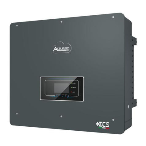
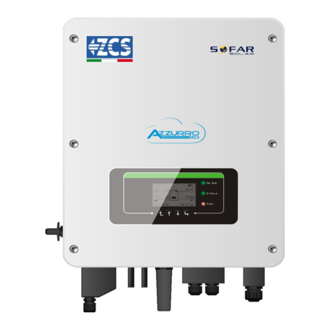
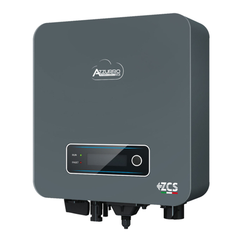
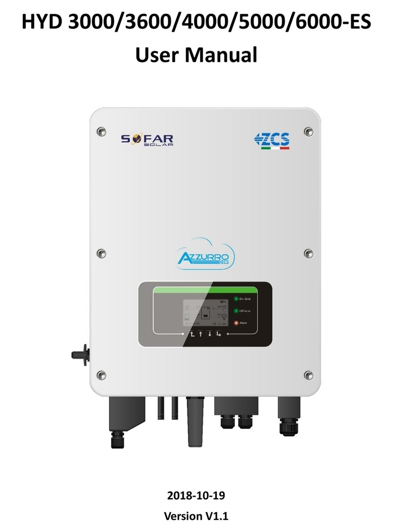
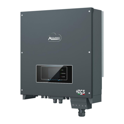
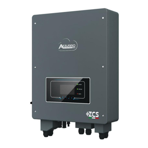
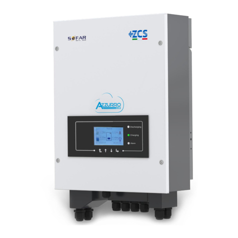
ZCS HYD 3000-ES User manual

ZCS HYD 3-6K ES hybrid inverter
User Manual
13 –06 - 2019
V1.1 (for firmware version V1.40 or higher)

2/50
User Manual for HYD 3-6 kw ES Hybrid Inverter - Rev. 1.1 del 13/06/2019
Identificazione: MD-AL-GI-00
Rev. 4.0 del 31.01.18 - Applicazione: GID
Table of Contents
1. Introduction.............................................................................................................................................................6
2. Preliminary safety instructions................................................................................................................................7
2.1. Safety Notes................................................................................................................................................7
2.2. Mounting and maintenance instructions ...................................................................................................7
2.3. Symbols on the inverter..............................................................................................................................9
3. Installation .............................................................................................................................................................10
3.1. Product overview......................................................................................................................................10
3.2. Contents of the packaging........................................................................................................................11
3.3. Installation environment ..........................................................................................................................11
3.4. Installation tools .......................................................................................................................................12
3.5. Wall installation position ..........................................................................................................................13
3.6. Mounting instructions ..............................................................................................................................13
4. Electrical connections............................................................................................................................................15
4.1. Connecting the battery.............................................................................................................................16
4.2. Photovoltaic connection...........................................................................................................................17
4.3. CT / CAN / RS485 / NTC –Pylontech Battery connection.........................................................................19
4.4. Grid connection ........................................................................................................................................21
4.5. Critical Load connection (EPS function)....................................................................................................22
5. Buttons and Indicator lights...................................................................................................................................24
5.1. Buttons......................................................................................................................................................24
5.2. Indicator lights and operating status ........................................................................................................24
6. Operation...............................................................................................................................................................25
6.1. Preliminary checks....................................................................................................................................25
6.2. Initial set up (follow carefully) ..................................................................................................................25
6.3. Commissioning .........................................................................................................................................29
6.4. Display menu ............................................................................................................................................30
6.4.1. Basic settings:...............................................................................................................................31
6.4.2. Advanced settings ........................................................................................................................36
6.4.3. Event list.......................................................................................................................................38
6.4.4. System Information interface.......................................................................................................38
6.4.5. Energy Statistics ...........................................................................................................................39
6.4.6. Software update...........................................................................................................................41

3/50
User Manual for HYD 3-6 kw ES Hybrid Inverter - Rev. 1.1 del 13/06/2019
Identificazione: MD-AL-GI-00
Rev. 4.0 del 31.01.18 - Applicazione: GID
7. Technical specifications .........................................................................................................................................42
8. Troubleshooting.....................................................................................................................................................44
9. Warranty................................................................................................................................................................50

4/50
User Manual for HYD 3-6 kw ES Hybrid Inverter - Rev. 1.1 del 13/06/2019
Identificazione: MD-AL-GI-00
Rev. 4.0 del 31.01.18 - Applicazione: GID
General instructions
This manual contains important safety instructions that must be followed during installation and maintenance
of the equipment.
Please keep these instructions!
This manual must be considered an integral part of the equipment and must always be available to everyone
who interacts with this equipment. The manual must always accompany the equipment, even when it is
transferred to another user or plant.
Copyright statement
The copyright of this manual belongs to Zucchetti Centro Sistemi S.p.A. No part of this manual may be copied
(including the software), reproduced or distributed in any form or by any means without the permission of
Zucchetti Centro Sistemi S.p.A. All rights reserved. ZCS reserves the right to final interpretation. This manual is
subject to change based on feedback from users, installers or customers. Please check our website
http://www.zcsazzuro.com for the latest version.
Zucchetti Centro Sistemi
Via Lungarno 305/A
52028, Terranuova Bracciolini (AR)
+39 055 91971
info@zcscompany.com
http://www.zcscompany.com

5/50
User Manual for HYD 3-6 kw ES Hybrid Inverter - Rev. 1.1 del 13/06/2019
Identificazione: MD-AL-GI-00
Rev. 4.0 del 31.01.18 - Applicazione: GID
Preface
General information
Please read this manual carefully before installation, operation or maintenance.
This manual contains important safety instructions that must be followed during installation and maintenance
of the system.
Scope
This manual describes the assembly, installation, electrical connections, commissioning, maintenance and
troubleshooting of the HYD 3-6K ES hybrid inverter.
Keep this manual so that it is accessible at all times.
Recipients
This manual is intended for qualified technical personnel (installers, technicians, electricians, technical support
personnel or anyone who is qualified and certified to operate a photovoltaic system), who are responsible for
installing and starting up the inverter in the photovoltaic and storage energy system and for operators of
photovoltaic and storage systems.

6/50
User Manual for HYD 3-6 kw ES Hybrid Inverter - Rev. 1.1 del 13/06/2019
Identificazione: MD-AL-GI-00
Rev. 4.0 del 31.01.18 - Applicazione: GID
1. Introduction
The HYD-ES hybrid inverter is used in photovoltaic systems with battery storage.
The energy produced by the photovoltaic system will be optimised for maximum self-consumption.
The HYD-ES inverter can operate in automatic mode and in time-of-use charge, charge/discharge mode. In
automatic mode, when the energy produced by the PV field is greater than that required by the utilities, the
HYD-ES inverter charges the battery using the surplus photovoltaic energy, and when the photovoltaic energy
is lower than that required, the inverter uses the energy stored in the battery to supply current to the local
load.
In the event of a power failure (or by switching on the inverter in Off-Grid mode), the HYD-ES inverter can
operate in Emergency Power Supply (EPS) mode. The HYD-ES inverter will use both the energy created by the
photovoltaic panels and the energy stored in the battery to supply energy to the critical load.
Figure 1 - Diagram of a system on which a HYD 3-6K ES hybrid is installed

7/50
User Manual for HYD 3-6 kw ES Hybrid Inverter - Rev. 1.1 del 13/06/2019
Identificazione: MD-AL-GI-00
Rev. 4.0 del 31.01.18 - Applicazione: GID
2. Preliminary safety instructions
Before installation, please read this manual carefully and make sure you fully understand its contents. The HYD-ES
inverter fully complies with the safety regulations. During installation, operation and maintenance, all operators
must follow the local safety guidelines. Improper operation may result in electric shock and/or damage to people
and property.
2.1. Safety Notes
Electrical installation and maintenance must be carried out by qualified electricians in accordance with the
local regulations.
The HYD-ES inverter may only be installed by qualified electricians and by those who are duly certified, in
accordance with the local authorities.
DO NOT place explosives or flammable materials, e.g. gasoline, kerosene, oil, wood, cotton or rags near the
batteries or the HYD-ES inverter.
Before maintenance, disconnect the AC connection, then the batteries and the photovoltaic system (PV1&PV2),
wait at least 5 minutes (capacitor discharge time) so as to prevent electric shock.
The HYD-ES inverter must be completely disconnected (BAT, PV & AC) during maintenance.
The HYD-ES inverter may reach high temperatures and have internal rotating parts during operation. Switch off
the HYD-ES inverter and wait for it to cool down before maintenance.
Keep children away from the batteries and from the HYD-ES inverter.
Do not open the front cover of the HYD-ES inverter. Opening the front cover will void the product warranty.
Damage caused by improper installation/operation is NOT covered by the product warranty.
2.2. Mounting and maintenance instructions
The battery must be protected against short circuits during transport and installation.
The HYD-ES inverter/batteries must be located in well-ventilated areas. Do not place the HYD-ES
inverter/batteries in a cabinet or in an airtight or poorly ventilated location. This could greatly impair the
performance and life of the system.
Keep the HYD-ES inverter and batteries away from direct sunlight. Do not bring the HYD-ES inverter and
batteries near ovens, flames or other heat sources as the battery may catch fire and cause an explosion.
The current capacity of the DC power cables (from the battery to the inverter) must be at least 90A. Use short
DC power cables to prevent voltage drops and power losses.
Use a multimeter to check the battery polarity and voltage before turning on the power. Make sure that the
connections are made according to the instructions in this manual.
Use the multimeter to check the PV voltage and polarity before closing the PV switch. Make sure that the
connections are made according to the instructions in this manual.
If you want to store the batteries without using them, disconnect them from the HYD-ES inverter and store
them in a cool, dry and well-ventilated area.

8/50
User Manual for HYD 3-6 kw ES Hybrid Inverter - Rev. 1.1 del 13/06/2019
Identificazione: MD-AL-GI-00
Rev. 4.0 del 31.01.18 - Applicazione: GID
Battery maintenance workers must have the skills and knowledge required to carry out this activity.
All the batteries connected in parallel must be of the same model and have the same firmware version. This
problem must be taken into consideration by the designer/installer, especially when replacing the batteries or
when modifying the existing storage system.
The HYD-ES inverter does not have an isolation transformer so the positive and negative poles of the PV string
do NOT have to be grounded, otherwise the inverter may be damaged. All non-current-carrying metal parts
(such as the PV module frame, PV rack, housing of the combiner box, and housing of the inverter) in the
photovoltaic power system must be connected to the ground.
Attention: Do not disassemble or puncture the battery. The electrolytes in the battery may be toxic and cause
damage to skin and eyes.
Attention: during installation and maintenance of the battery, please follow the rules below.
a) Remove watches, rings and other metal objects.
b) Only use tools with insulated handles.
c) Wear rubber gloves and shoes.
d) Do not place tools or metal objects on top of the battery.
e) Turn off the HYD-ES inverter and batteries before connecting/disconnecting the battery terminals.
f) Both the positive pole and the negative poles must be insulated from the ground.

9/50
User Manual for HYD 3-6 kw ES Hybrid Inverter - Rev. 1.1 del 13/06/2019
Identificazione: MD-AL-GI-00
Rev. 4.0 del 31.01.18 - Applicazione: GID
2.3. Symbols on the inverter
Some safety symbols are found on the inverter. Read and understand the content of the symbols before
installing the inverter.
This symbol indicates a hazardous situation which, if not avoided, will result in
injury.
Risk of electric shock; wait at least 5 minutes before switching off the HYD-ES
inverter.
Be careful of high voltage and electric shock.
Be careful of hot surface.
Comply with the European Conformity (EC) certification.
Ground terminal.
Read this manual before installing the ZCS HYD-ES inverter.
This indicates the degree of protection of the equipment in accordance with the
IEC 70-1 (EN 60529 June 1997) standard.
Positive pole and negative pole of the DC voltage (Photovoltaic and battery).
This side up. The HYD-ES inverter must always be transported, handled and stored
in such a way that the arrows point upwards at all times.

10/50
User Manual for HYD 3-6 kw ES Hybrid Inverter - Rev. 1.1 del 13/06/2019
Identificazione: MD-AL-GI-00
Rev. 4.0 del 31.01.18 - Applicazione: GID
3. Installation
3.1. Product overview
The HYD-ES inverter is subjected to strict controls and inspection before packaging and delivery. Do not turn
the HYD-ES inverter upside down during delivery.
Carefully check the packaging and product fittings before installation.
Caution
Figure 2 - Diagram of a system on which a HYD 3-6K ES hybrid is installed
1
DC switch
6
Current transformer port
2
Battery input terminals
7
Critical load connection port
3
PV input terminals
8
Grid connection port
4
Wi-Fi/GPRS adaptor
9
LCD
5
BMS communication interface
10
Vent valve

11/50
User Manual for HYD 3-6 kw ES Hybrid Inverter - Rev. 1.1 del 13/06/2019
Identificazione: MD-AL-GI-00
Rev. 4.0 del 31.01.18 - Applicazione: GID
3.2. Contents of the packaging
Carefully inspect the packaging and accessories before installation. It should contain the following accessories:
1 mounting bracket
6 AC terminals
2 M5 screws
2 battery terminals
8 M6 flat washers
8 expansion plugs
4 terminal caps
2 TC terminals
1 current transformer
1 user manual
1 warranty
1 quality certificate
1 communication cable
2 PV+ input terminals
2 PV- input terminals
1 NTC (3M long)
Figure 3 –Components and accessories inside in the packaging
3.3. Installation environment
Choose a dry, clean and tidy place, suitable for installation.
Ambient temperature range: -25°C –60°C
Relative humidity: 0 –100% (non-condensing)
The HYD-ES inverter must be installed in a well-ventilated area.
Do not place flammable or explosive materials near the HYD-ES inverter.
The AC overvoltage of the HYD-ES inverter belongs to Category III.
Maximum altitude: 2000m

12/50
User Manual for HYD 3-6 kw ES Hybrid Inverter - Rev. 1.1 del 13/06/2019
Identificazione: MD-AL-GI-00
Rev. 4.0 del 31.01.18 - Applicazione: GID
3.4. Installation tools
Prepare the following tools before installation:
Number
Tool
Model
Function
1
Percussion drill
Recommended diameter of 6mm
Used for drilling the wall
2
Screwdriver
Used for the wiring
3
Cable stripper
Used for stripping the wires
4
4mm Allen key
Used for tightening the screws to
connect the rear panel of the
inverter
5
Crimping tools
Used for crimping the power cables
6
Multi-meter
Used for checking the grounding
connection
7
Marker pen
Used for marking
8
Tape measure
Used for measuring distances
9
Level
Used for making sure that the rear
panel is installed correctly
10
ESD gloves
Must be worn by operators
11
Safety goggles
Must be worn by operators

13/50
User Manual for HYD 3-6 kw ES Hybrid Inverter - Rev. 1.1 del 13/06/2019
Identificazione: MD-AL-GI-00
Rev. 4.0 del 31.01.18 - Applicazione: GID
12
Dust mask
Must be worn by operators
3.5. Wall installation position
The HYD-ES inverter must be mounted vertically (to ensure rapid heat dissipation). Install the HYD-ES inverter
in a location protected against direct sunlight and possible snow accumulation. Make sure that the installation
position is well ventilated.
Figure 4 –Installation position of the HYD-ES inverter
3.6. Mounting instructions
Step 1: Position the mounting bracket on the wall, mark the 8 fixing points using the marker. Drill 8 holes (6
mm drill bit) in the wall.
Step 2: Insert the expansion screws vertically into the hole, make sure that the insertion depth is neither too
shallow nor too deep.
Step 3: Fix the mounting bracket to the wall using dowels and flat washers.

14/50
User Manual for HYD 3-6 kw ES Hybrid Inverter - Rev. 1.1 del 13/06/2019
Identificazione: MD-AL-GI-00
Rev. 4.0 del 31.01.18 - Applicazione: GID
Step 4: Place the HYD-ES inverter on the mounting bracket.
Step 5: Use the grounding hole of the heatsink to ground the HYD-ES inverter.
Step 6: OPTIONAL - the NYD-Es inverter can be fixed to the mounting bracket.
Step 5 Step 6
Note: for safety reasons, ZCS Spa and/or its partners may not carry out any technical repairs or maintenance
work, or move the inverter or battery pack from and to the ground if it is installed at a height of more than 180
cm from the ground.
Inverters and/or battery packs installed at higher heights must be moved to the ground before they can be
repaired or serviced.

15/50
User Manual for HYD 3-6 kw ES Hybrid Inverter - Rev. 1.1 del 13/06/2019
Identificazione: MD-AL-GI-00
Rev. 4.0 del 31.01.18 - Applicazione: GID
Figure 5 –Instructions for installing the storage inverter and battery pack
4. Electrical connections
High voltages in power conversion circuits. Danger of death by electrocution or serious
burns.
All work on the photovoltaic modules, inverters and battery systems must be carried out by
qualified technicians.
Wear rubber gloves and protective clothing (protective eyewear and boots) when working
on high voltage/high current systems such as inverters and battery systems.
Caution
The HYD-ES hybrid inverter was designed to be used in photovoltaic systems with battery
storage. If not used as designed, the protection provided by the equipment may be
impaired.
Caution

16/50
User Manual for HYD 3-6 kw ES Hybrid Inverter - Rev. 1.1 del 13/06/2019
Identificazione: MD-AL-GI-00
Rev. 4.0 del 31.01.18 - Applicazione: GID
Figure 6 –Electrical Connections
4.1. Connecting the battery
Figure 7 –Connecting the battery (measure polarity/voltage of the battery cables before connection)
Step 1: Loosen the 4 screws (A) using a screwdriver (Fig. 6).
Step 2: Remove the waterproof cover (B), loosen the cable gland (C), and then remove the cap (G).

17/50
User Manual for HYD 3-6 kw ES Hybrid Inverter - Rev. 1.1 del 13/06/2019
Identificazione: MD-AL-GI-00
Rev. 4.0 del 31.01.18 - Applicazione: GID
Step 3: Route the battery cables (F) through the cable gland, then connect the battery wires using the OT
terminal (E).
Step 4: Fasten the waterproof cover using the 4 screws.
4.2. Photovoltaic connection
Recommended specifications for DC input cables
Cross-sectional area (mm2)
Outer diameter of cable (mm2)
Range
Recommended value
4.0~6.0
4,0
4.5~7.8
Procedure:
Step 1: Prepare the positive and negative photovoltaic cables
Figure 8 –Preparing the positive and negative photovoltaic cables
Step 2: Insert the crimped positive and negative cables into the corresponding photovoltaic connectors
Figure 9 –Preparing the positive and negative photovoltaic connectors
Step 3: Make sure that the DC voltage of each photovoltaic string is less than 600V DC and that the polarities of

18/50
User Manual for HYD 3-6 kw ES Hybrid Inverter - Rev. 1.1 del 13/06/2019
Identificazione: MD-AL-GI-00
Rev. 4.0 del 31.01.18 - Applicazione: GID
the photovoltaic cables are correct. Insert the positive and negative connectors of the HYD-ES inverter until
you hear a “click” sound, as show in Fig. 9.
Figure 10 –Connecting the photovoltaic connectors
Before removing the positive and negative PV connectors, make sure that the DC
CIRCUIT BREAKER is OPEN.
Caution
Follow-up procedure
Use a MC4 wrench to disconnect the photovoltaic connectors, as shown in figure 10.
Figure 11 –Disconnecting the photovoltaic connectors
Connect the HYD-ES inverter to the photovoltaic strings using DC input power cables.
Select the input mode: the HYD-ES inverter has two MPPTs, which can operate both independently and in
parallel. The user can choose the appropriate MPPT operating mode according to the design of the system.
Independent mode (default):
If the strings are different (e.g. installed on two separate flaps or consisting of a different number of panels),
the input model must be set to “independent mode.”
The setting method is described in section 6.4.1.
Parallel mode:
If the strings are connected in parallel, the input mode must be set to “parallel mode.”
The setting method is described in section 6.4.1.

19/50
User Manual for HYD 3-6 kw ES Hybrid Inverter - Rev. 1.1 del 13/06/2019
Identificazione: MD-AL-GI-00
Rev. 4.0 del 31.01.18 - Applicazione: GID
Note
Depending on the type of inverter, select the appropriate inverter accessories (cables, fuse holders, fuses,
switches, etc). The open-circuit voltage of the photovoltaic system must be lower than the maximum DC input
voltage of the inverter. The output voltage of the strings must be compatible with the MPPT voltage range.
The positive and negative poles of the panel on the inverter must be connected separately. The power cable
must be suitable for photovoltaic applications.
Note
Both MPPT inputs of the inverter should be populated, even if the system only has one string. If the strings are
arranged in parallel, it is recommended to use a Y or T connection cable to double the input currents from the
PV field and to populate both MPPT inputs of the inverter, as shown in the figure. If the string arrangement is
independent, simply connect the two strings to the two MPPTs of the inverter.
Figure 12 –Y-branch connection cable for solar panels
4.3. CT / CAN / RS485 / NTC –Pylontech Battery connection
The CTa (current transformer) can measure the value and direction of the AC current. Refer to figure 12 for the
correct connection of the CTa.

20/50
User Manual for HYD 3-6 kw ES Hybrid Inverter - Rev. 1.1 del 13/06/2019
Identificazione: MD-AL-GI-00
Rev. 4.0 del 31.01.18 - Applicazione: GID
Figure 13 –CT connections
Step 1: Refer to figure 12 for the correct position of the CTa. Wrap the CTa around the L wire of the mains
power supply.
Step 2: If necessary, network cables and terminal caps can be used to extend the CTa wires; the maximum
length of the cable is 200m.
TC Wire
Extension (network cable)
HYD-ES inverter
Red
Orange / white orange / brown / white brown
CT+
Black
Green / white green / blue / white blue
CT-
Figure 14 –CT / CAN / RS485 /NTS connections
This manual suits for next models
3
Table of contents
Other ZCS Inverter manuals

ZCS
ZCS AZZYRRO 3-6-ZSS-HP User manual

ZCS
ZCS 1100TL-G3 User manual

ZCS
ZCS HYDxxxxES Series User manual

ZCS
ZCS Azzurro 3000SP User manual

ZCS
ZCS AZZURRO HYD3000 User manual

ZCS
ZCS ZCS 1.1K-3KTL User manual

ZCS
ZCS AZZURRO Series User manual

ZCS
ZCS AZZURRO 1PH HYD3000-ZP1 User manual

ZCS
ZCS Azzurro 3PH HYD5000 ZSS User manual

ZCS
ZCS TL Series User manual