SCOV SV600 Series User manual
SV880 系列
Users’ Manual
SV600 Series
Ver.1.0
SHENZHEN SCOV ELECTRIC TECHNOLOGIES CO., LTD

SV600 Series User Manual Version: V1.0-01
Foreword
Thank you for purchasing and using SV600 Series frequency inverter.
SV600 series inverter is a general-purpose vector inverter, which is mainly used to control and
adjust the speed of three-phase AC asynchronous motor. It adopts space SVPWM vector control
technology to achieve high torque output at low speed. With good dynamic characteristics and
overload capacity, it can meet the various needs of users.
This series of inverters is suitable for most motor-driven fields, including: textile, papermaking,
packaging, food, fans, water pumps and various automatic production equipment. As a speed
control device, it has strong load adaptability, stable operation and good reliability.
The manual provides users with relevant precautions such as installation and wiring, parameter
setting, operation debugging and daily maintenance. In order to ensure the correct installation
and operation of the inverter, please read this manual carefully before use.
If any difficulties or special requirements during the use, please contact the distributors or our
company directly, we will serve you wholeheartedly.

SV600 Series User Manual Version:V1.0-01
Content
1 Safety information and precautions...............................................................................................................1
1.1 Safety precautions......................................................................................................................................1
1.1.1 Safety precautions before installation..................................................................................1
1.1.2 Safety precautions for transporting and installation ....................................................1
1.1.3 Safety precautions for wiring....................................................................................................2
1.1.4 Safety precautions for debugging and operation ............................................................3
2 Product Introduction.............................................................................................................................................4
2.1 SV600 models introduction ...................................................................................................................4
2.2 Inverter nameplate.....................................................................................................................................4
2.3 Product models list ....................................................................................................................................5
2.4 Product technical specifications..........................................................................................................9
3 Mechanical Installation .....................................................................................................................................12
3.1 Installation ..................................................................................................................................................12
3.1.1 Installation Environment.........................................................................................................12
3.2 Installation direction and space........................................................................................................13
3.2.1 Installation Space.........................................................................................................................13
3.2.2 Installation direction..................................................................................................................15
3.3 Installation Guidance .............................................................................................................................15
3.3.1 Wall-mounted Installation ......................................................................................................16
3.4 Disassembly and installation of keyboard...................................................................................16
3.4.1 Disassembly of the keyboard .................................................................................................16
3.4.2 Installation of the keyboard....................................................................................................16
3.5 SV600 appearance and installation dimensions.......................................................................17
3.6 Keyboard appearance and installation dimensions................................................................21
4 Electrical wiring and precautions ................................................................................................................23
4.1Main circuit electrical wiring ..............................................................................................................23
4.1.1 Arrangement and definition of main circuit terminals..............................................23
4.1.2 Installation size and wire selection of power terminals...........................................26
4.2 Description of control terminals ......................................................................................................28
4.2.1 Connection Function Description of Conversion Terminal .....................................30
4.2.2 Wiring method of frequency inverter electric control circuit ................................32
4.2.3 Wiring description of control signal terminals .............................................................33
4.3 EMC.................................................................................................................................................................34
4.3.1 Definitions of related terms....................................................................................................34
4.3.2 Introduction of EMC standards.............................................................................................35
4.3.3 Installation of EMC input filter on Power supply input.............................................35
4.3.4 Installation of AC input reactor on power supply input ...........................................35
4.3.5 Installation of AC output reactor on frequency inverter output ...........................36
4.3.6 Installation of external DC reactor ......................................................................................36
4.3.7 Shielded cable................................................................................................................................36

Version:V1.0-01 SV600 Series User Manual
5 Operation and keyboard display...................................................................................................................40
5.1 Function and operation of keyboard ..............................................................................................40
5.1.1 Function and name of each part ...........................................................................................40
5.1.2 Description of LED indicators................................................................................................41
5.1.3 Description of function code viewing and modification method .........................41
5.2 Setting and self-learning of motor characteristic parameters ...........................................42
5.2.1 Motor parameters need to be set .........................................................................................42
5.2.2 Self-learning of motor parameters......................................................................................43
6 Parameters List .....................................................................................................................................................44
7 Parameters Description ....................................................................................................................................77
Group P0:Basic Function Parameters ................................................................................................77
Group P1: Motor 1 Parameters
...................................................................................................................84
Group P2: Motor 1 vector control parameters ..................................................................................86
Group P3: V/F Control Parameters
..........................................................................................................89
Group P4: Input Terminals..........................................................................................................................94
Group P5: Output Terminals ...................................................................................................................104
Group P6: Start/Stop Control .................................................................................................................110
Group P7: Keyboard and Display ..........................................................................................................114
Group P8: Auxiliary Functions ...............................................................................................................118
Group F9: Fault and Protection.............................................................................................................. 128
Group PA: PID function
............................................................................................................................... 137
Group Pb: Swing frequency, fixed length and count functions
.................................................. 142
Group PC: Multi-segment instruction, simple PLC functions
..................................................... 144
Group Pd: Communication parameters
...............................................................................................148
Group PP: Function Code Management
............................................................................................... 150
Group A0: Torque Control Parameters
................................................................................................152
Group A1: Virtual IO
..................................................................................................................................... 154
Group A2: Motor 2 Parameters
............................................................................................................... 157
Group A5: Control Optimization Parameters
.................................................................................... 160
Group A6: AI Curve Setting
....................................................................................................................... 163
Group AC: Correction of AI and AO
........................................................................................................ 165
Group U0: Monitor Parameters..............................................................................................................167
8 Maintenance and Fault Diagnosis ............................................................................................................. 172
8.1 Daily and periodic inspection .........................................................................................................172
8.1.1 Wearing parts replacement .................................................................................................172
8.1.2 Inverter storage .........................................................................................................................172
8.2 Warranty Agreement........................................................................................................................... 173
8.3 Faults and Solutions ............................................................................................................................173
8.4 Common faults and solutions.......................................................................................................... 177
Appendix A: Braking............................................................................................................................................ 179
A.1 Selection of braking unit and braking resistor ....................................................................... 179
A.1.1 Selection of braking resistor resistance ........................................................................179
A.1.2 Selection of braking resistor power ................................................................................179

SV600 Series User Manual Version:V1.0-01
A.1.3 Brake Resistance Wiring....................................................................................................... 181
Appendix B: Modbus Communication ........................................................................................................183
B.1 Modbus communication....................................................................................................................183
B.1.1 Support protocol....................................................................................................................... 183
B.1.2 Interface mode........................................................................................................................... 183
B.1.3 Format of protocol ...................................................................................................................183
B.1.4 Modbus Functions.................................................................................................................... 183
B.1.5 CRC16 function.......................................................................................................................... 185
B.2 Function code parameter addressing rules .............................................................................186
B.3 Description of communication parameters for Pd Group................................................. 189

SV600 Series User Manual 1 Safety information and precautions
1
1 Safety information and precautions
1.1 Safety precautions
Users should familiar with the manual and other related technical materials and be sure to
follow the safety precautions required in this chapter when installing, operating, and
maintaining the product. At the same time, you should also know about the mechanical
knowledge, safety information, precaution and so on.
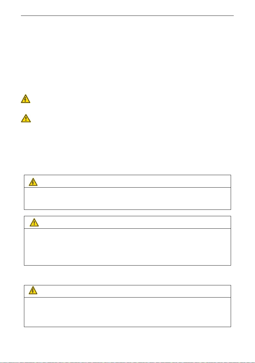
In the manual, safety precautions are classified into <Danger> and <Warning> two categories:
DANGER: Failure to comply with the notice will result in fire, serious injury or even
death.
WARNING: Failure to comply with the notice will result in personal injury or devices and
property damage, even accidents.
Both marks which used in the manual indicate that there is an important content of safety.
Failure to comply with those notices may lead to death, serious injury, damage to the products
and related machines and systems. SCOV will assume no liability or responsibility for any
injury, damage or loss caused by improper operation.
1.1.1 Safety precautions before installation
DANGER
To avoid damage expanding and injury, please don't install the frequency inverter if you find water
seepage, component missing or damaged.
Do not install it if the packing list not conform to the product.
WARNING
Do not touch the components with your hands. Electrostatic may cause damages.
The withstand voltage test has been done before leaving the factory. The users do not need to perform
the test on the inverter again. It may cause damage to the inverter insulation and internal components.
Do not use the product when the rated value in the nameplate is inconsistent with the order
requirements.
1.1.2 Safety precautions for transporting and installation
DANGER
Install the equipment longitudinally on incombustible objects such as metal, and keep it away from
combustible materials. Otherwise it may result in a fire.
Install the equipment in the place that can bear the weight to avoid danger of injury due to falling. Do
not install the equipment in an environment containing explosive gas. It may has danger of explosion.

1 Safety information and precautions SV600 Series User Manual
2
WARNING
Lift and handle the inverter gently when carrying, do not hold the front cover with one hand only. It
may hurt your feet or damage the inverter if it falls off.
Prevent conductive objects such as screws and metal shavings from falling into the inverter during
installation. It may cause the inverter to malfunction or be damaged.
Avoid places with harsh environments such as oil mist, dust suspension, vibration, etc. When
installing in a cabinet, please ensure that the ambient temperature in the cabinet is within the allowed
temperature range of the inverter. Otherwise it may cause the inverter to malfunction or be damaged.
1.1.3 Safety precautions for wiring
DANGER
Do not perform wiring work expect for electrical construction professionals. Otherwise it has risk of
electric shock and fire.
Before wiring the inverter terminals, you must cut off all power connected to the inverter. The waiting
time after the power is cut off is not shorter than the time marked on the inverter. Also ensure the DC voltage
between +1 ~- or +2~- is less than 30V. What's more, the inverter must properly regulate the ground wire.
Otherwise it has a danger of electric shock.
Please connect the input power cable and the motor cable correctly. Never connect the input power to
the output terminals (U, V, W) of the inverter. Pay attention to the marks on the terminals and do not connect
the wrong wires. Otherwise it has risk of damage to the inverter.
Never connect the braking resistor directly between the DC bus positive terminal +1 or +2 and the
negative terminal -. Otherwise it has risk of fire and damage to the inverter.
The main circuit terminal wiring screws must be tightened well. For the wire diameter, please refer to
the recommendations in the manual. Otherwise it has risk of fire and damage to the inverter.
It is forbidden to connect AC220V voltage level signals to terminals except for the control terminals
TA, TB, TC, otherwise is has risk of damage to the inverter.
WARNING
Ensure that the rated voltage of the inverter is consistent with the voltage of the AC power supply.
Otherwise it may cause damage to the inverter.
The encoder signal line should uses shielded wire, and the single end of the shield layer should
reliably grounded. Otherwise it may cause the inverter to malfunction.

SV600 Series User Manual 1 Safety information and precautions
3
1.1.4 Safety precautions for debugging and operation
WARNING
Do not touch the fan, radiator or braking resistor directly. May cause mechanical injury and burns.
Do not use the input contactor on/off frequently to control the start and stop of the frequency inverter.
May cause damage to the inverter.
Check the allowable operating range of the motor and machine before operating as it is very easy for
the inverter to drive the motor from low speed to high speed. Otherwise it may cause equipment damage.
DANGER
Ensure the front cover installed well before connect the input power supply. After power-on, do not
open the cover and operate it as there is a high voltage inside. Otherwise it has a danger of electric shock.
Please ensure the safety and reliability around the motor and mechanical load during motor electric
parameters auto-tuning and the inverter operation. Otherwise it has risk of injury.
Non-professional technicians are prohibited from testing signals during power-on. Otherwise it has
risk of electric shock and damage to the inverter.
Forbidden to repair the motor and mechanical equipment during power-on. Otherwise it has risk of
electric shock and personal injury.
2 Product Introduction SV600 Series User Manual
4
2 Product Introduction
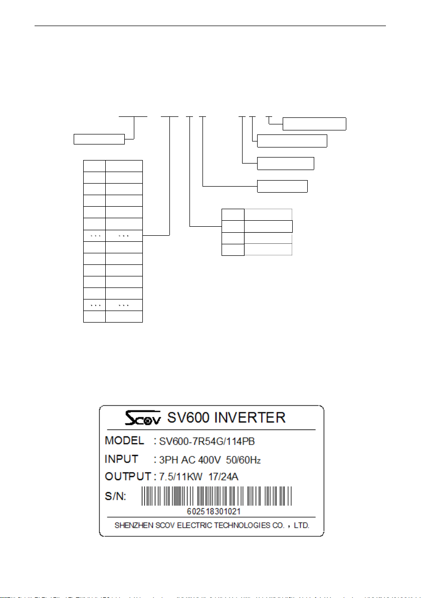
2.1 SV600 models introduction
Fig. 2-1 Model description
2.2 Inverter nameplate
A nameplate indicating the type and rating of the inverter is affixed to the right side of the
inverter case. The nameplate example of SV600 series is as follow:
Fig. 2-2 SV600 inverter nameplate
55KW
90 90KW
630
5R5
630KW
132KW
75KW
11
110KW110
7R5
132
75
Mark Power
4R0
7.5KW
11KW
55
5.5KW
4
5
3PH AC 380V
3PH AC 480V
Mark AC 230V
-
Note:For AC 230V grade,it has two types for choose.
1PH 230V input and 3PH 230V input.
The model with -S mark is 1PH AC 230V type.
The model without -S mark is 3PH AC 230V type.
SV600
4.0KW
S
S:Single phase input
P:Pump/Fan Type
B:Built-in braking unit
2
-4 G / 11 4 P B
G:General Type
Voltage grade
SV600 series
7R5
2R2 2.2KW

SV600 Series User Manual 2 Product Introduction
5
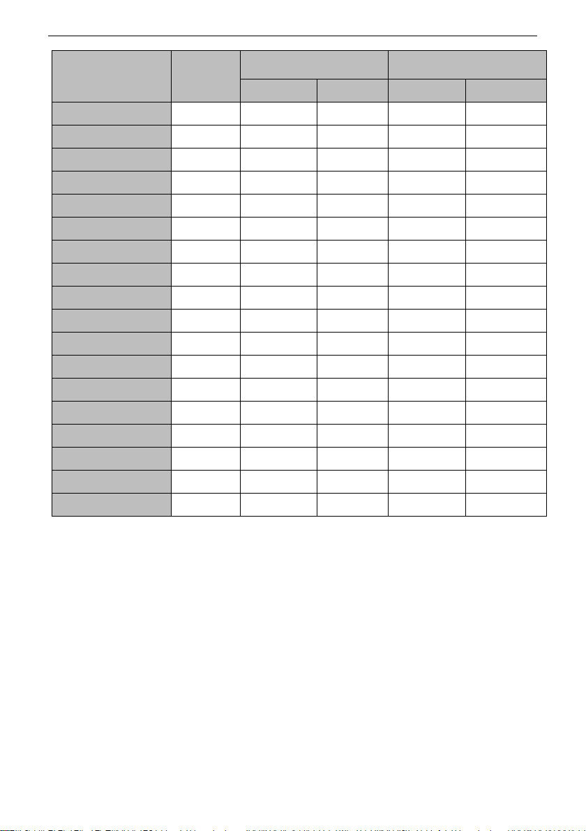
2.3 Product models list
Table 2-1 Models and Specifications for 230V grade
Inverter model
Power supply capacity
KVA
Input current
A
Rated Output
current A
Adapted Motor
KW
Single-phase power supply: 230V(-15%~+20%) 50/60 Hz
SV600-0R752GB-S
1.5
8.2
4.04
0.75
SV600-1R52GB-S
3
14
7.3
1.5
SV600-2R22GB-S
4
23
9.6
2.2
SV600-4R02GB-S
7
33
17
4.0
SV600-5R52GB-S
12
55
24
5.5
SV600-7R52GB-S
15
70
32.5
7.5
SV600-112GB-S
20
95
46
11
SV600-152GB-S
29
130
62.5
15
SV600-18R52G-S
35
160
75.5
18.5
SV600-222G-S
42
190
92.5
22
SV600-302G-S
50
230
111
30
Three phase power supply: 230V(-15%~+20%) 50/60 Hz
SV600-0R42GB
1.5
3.4
2.5
0.4
SV600-0R752GB
3
5
4.04
0.75
SV600-1R52GB
5.9
10.5
7.3
1.5
SV600-2R22GB
5.9
10.5
10
2.2
SV600-4R02GB
11
20.5
17
4.0
SV600-5R52GB
17
26
24
5.5
SV600-7R52GB
21
35
32.5
7.5
SV600-112GB
30
46.5
46
11
SV600-152GB
40
62
62
15
SV600-18R52G
57
76
76
18.5
SV600-222G
69
92
92
22
SV600-302G
85
113
111
30
SV600-452G
134
180
169
45

2 Product Introduction SV600 Series User Manual
6
Inverter model
Power supply capacity
KVA
Input current
A
Rated Output
current A
Adapted Motor
KW
SV600-552G
160
214
210
55
SV600-752G
192
256
246
75
SV600-902G
231
307
300
90
SV600-1102G
243
385
370
110
SV600-1322G
318
468
460
132
SV600-1602G
355
525
510
160
SV600-1852G
396
600
600
185
Table 2-2 Models and Specifications for 380V and 480V grade
Inverter model
Power supply
capacity
KVA
Output current
A
Adapted motor
KW
G type
P type
G type
P type
Three-phase power supply: 380V(-15%~+20%) 50/60 Hz
SV600-0R754G/1R54PB
1.5
2.5
4.04
0.75
1.5
SV600-1R54G/2R24PB
3
4.04
5.5
1.5
2.2
SV600-2R24G/4R04PB
4
5.5
10
2.2
4.0
SV600-4R04G/5R54PB
5.9
10
13
4.0
5.5
SV600-5R54G/7R54PB
8.9
13
17
5.5
7.5
SV600-7R54G/114PB
11
17
24
7.5
11
SV600-114G/154PB
17
24
32.5
11
15
SV600-154G/18R54PB
21
32.5
38
15
18.5
SV600-18R54G/224PB
24
38
46
18.5
22
SV600-224G/304PB
30
46
62.5
22
30
SV600-304G/374PB
40
62
75.5
30
37
SV600-374G/454P
57
75.5
92.5
37
45
SV600-454G/554P
69
92.5
111
45
55
SV600-554G/754P
85
111
146
55
75
SV600-754G/904P
114
146
169
75
90
SV600-904G/1104P
134
169
210
90
110
SV600-1104G/1324P
160
210
246
110
132

SV600 Series User Manual 2 Product Introduction
7
Inverter model
Power supply
capacity
KVA
Output current
A
Adapted motor
KW
G type
P type
G type
P type
SV600-1324G/1604P
192
246
300
132
160
SV600-1604G/1854P
200
300
350
160
185
SV600-1854G/2004P
231
350
370
185
200
SV600-2004G/2204P
243
370
415
200
220
SV600-2204G/2504P
273
415
460
220
250
SV600-2504G/2804P
318
460
510
250
280
SV600-2804G/3154P
355
510
600
280
315
SV600-3154G/3554P
396
600
660
315
355
SV600-3554G/4004P
500
660
740
355
400
SV600-4004G/4504P
500
740
820
400
450
SV600-4504G/5004P
565
820
920
450
500
SV600-5004G/5604P
625
920
990
500
560
SV600-5604G/6304P
690
990
1160
560
630
SV600-6304G
770
1160
/
630
/
Three phase power supply: 480V(15%~+15%) 50/60 Hz
SV600-0R755G/1R55PB
1.5
2.5
4.04
0.75
1.5
SV600-1R55G/2R25PB
3
4.04
5.5
1.5
2.2
SV600-2R25G/4R05PB
4
5.5
10
2.2
4.0
SV600-4R05G/5R55PB
5.9
10
13
4.0
5.5
SV600-5R55G/7R55PB
8.9
13
17
5.5
7.5
SV600-7R55G/115PB
11
17
24
7.5
11
SV600-115G/155PB
17
24
32.5
11
15
SV600-155G/18R55PB
21
32.5
38
15
18.5
SV600-18R55G/225PB
24
38
46
18.5
22
SV600-225G/305PB
30
46
62.5
22
30
SV600-305G/375PB
40
62
75.5
30
37
SV600-375G/455P
57
75.5
92.5
37
45
SV600-455G/555P
69
92.5
111
45
55
2 Product Introduction SV600 Series User Manual
8
Inverter model
Power supply
capacity
KVA
Output current
A
Adapted motor
KW
G type
P type
G type
P type
SV600-555G/755P
85
111
146
55
75
SV600-755G/905P
114
146
169
75
90
SV600-905G/1105P
134
169
210
90
110
SV600-1105G/1325P
160
210
246
110
132
SV600-1325G/1605P
192
246
300
132
160
SV600-1605G/1855P
200
300
350
160
185
SV600-1855G/2005P
231
350
370
185
200
SV600-2005G/2205P
243
370
415
200
220
SV600-2205G/2505P
273
415
460
220
250
SV600-2505G/2805P
318
460
510
250
280
SV600-2805G/3155P
355
510
600
280
315
SV600-3155G/3555P
396
600
660
315
355
SV600-3555G/4005P
500
660
740
355
400
SV600-4005G/4505P
500
740
820
400
450
SV600-4505G/5005P
565
820
920
450
500
SV600-5005G/5605P
625
920
990
500
560
SV600-5605G/6305P
690
990
1160
560
630
SV600-6305G
770
1160
/
630
/

SV600 Series User Manual 2 Product Introduction
9
2.4 Product technical specifications
Item
Specifications
Input
Voltage and frequency
Single phase 230V,50Hz/60Hz
Three phase 230V, 50Hz/60Hz
Three phase 380V, 50Hz/60Hz
Three phase 480V, 50Hz/60Hz
Allowed volt. range
Single phase 230V:200V~260V;
Three phase 230V, 200V~260V;
Three phase 380V, 320V~460V;
Three phase 480V, 380V~528V;
Output
Voltage
3PH 0~Input voltage
Frequency
0~300Hz(SVC vector control)
0~3200Hz(V/F control)
Overload capacity
G type:150% for 1mint, 180% for 3s.
P type:120% for 1 mint, 150% for 3s.
Control performance
Control mode
Speed sensorless vector control(SVC)
V/F control
Speed regulation range
1:100(SVC control mode)
1:50(V/F control mode)
Start-up torque
0.5Hz/150%(SVC control mode)
1.0Hz/150% (V/F control mode)
Speed stability accuracy
≤±0.5% of rating synchronous speed (SVC)
Frequency precision
Digital setting:max. frequency*±0.01%;Analog setting:Max.
frequency*±0.5%
Frequency
resolution
Analog
setting
0.1% of Max. frequency
Digital setting
The precision less than 100HZ:0.01Hz
High pulse
setting
0.1% of Max. frequency
Torque boost
Manual torque boost: 0.1~12.0%
V/F curve
Straight-line V/F curve;
Multi-point V/F curve
N-power V/F curve (1.2-power, 1.4-power, 1.6-power, 1.8-power,
square)
V/F separation
Complete separation
Half separation
Acceleration/Deceleration
curves
Linear and “S” curves acceleration and deceleration for selection
Four groups ofAcc./Dec. time available.
Braking
Power
consumption
braking
The model with “B” mark has built-in braking unit. Install braking
resistor between P+ and PB when needed.
For model without braking unit, you can add external braking unit
and braking resistor.
2 Product Introduction SV600 Series User Manual
10
DC braking
DC braking frequency: 0.00 Hz to maximum frequency
Braking time: 0.0–36.0s
Braking action current value: 0.0%–100.0%
JOG RUN
JOG frequency range: 0.00–50.00 Hz
JOG acceleration/deceleration time: 0.0–6500.0s
Multi-speed
Total 16 speeds can be selected by simple PLC function or the
combination of 4 DI terminals.
PID control
Be convenient to make closed-loop system which used for constant
pressure water supply or air compressor.
Automatic voltage regulate
(AVR)
Automatically keep constant output voltage when the power supply
voltage changes.
Automatic current limiting
Automatic current limiting avoids the malfunction of frequent
overcurrent causing trip during operation
Carrier modulation
Modulate carrier automatically based on the characteristic of load.
Speed tracking
Smoothly restart the rotating motor without overcurrent
Running function
Control command
Keyboard control, terminal control, communication control
supported and can be selected by many methods.
Frequency setting
source
Main and auxiliary frequency setting, analog, high pulse input,
communication setting and so on.
Those frequency setting sources also can be switched over by
terminals DI or keys on the keyboard.
Binding function
The control command and frequency setting source can be bond
arbitrarily, changes synchronously.
Input and output char-acter
Digital input channel
6 digital input (DI)
6 virtal digital input (VDI).
The function selection of each DI, please refer to Group P4.
Analog input channel
AI1: 4~20mAor 0~10V
AI2: 4~20mAor 0~10V
Pulse output channel
HDOP:High pulse output,0~20kHz
Analog output channel
AO1:4~20mAor 0~10V
AO2:0~10V
Unique feature
Rapid current limiting
Limit the output current of the inverter during operation and avoids
overcurrent fault occurs.
Fixed length control
Can realize fixed length control
Timing control
Timing control function:setting time range:0.1Min ~6500.0Min
Virtual terminal
6 virtal digital input (VDI) and 4 virtal digital output (VDO) for
choose, realizing simple logical control.
Keyboard
LED display
5 LED display for showing setting frequency, output frequency,
output voltage, output current and so on.
Lock the button
Lock all or part of the keys on the keyboard.
SV600 Series User Manual 2 Product Introduction
11
Protection function
Short circuit detection, short circuit to ground detection, input and
output loss phase detection, overcurrent, overvoltage,
undervoltage, overheat, overload, underload, contactor protection,
terminals protection and so on.
Ambient
Use ambient
Indoor, not bare to sunlight, no dust, no corrosive gas, no
flammable gas, no vapor, no water drop or salt etc.
Altitude
Less than 1000 meters.(10% de-rating using for each 1000 meters
when over 1000 meters.)
Ambient temperature
-10℃ ~ +40℃(under ambient temperature 40℃ ~ 50℃,please
reduce the volume or strengthen heat sink)
Ambient humidity
Less than 95%RH,without condenses
Vibration
Smaller than5.9m/s ²(0.6g)
Storage temperature
-40℃~+70℃
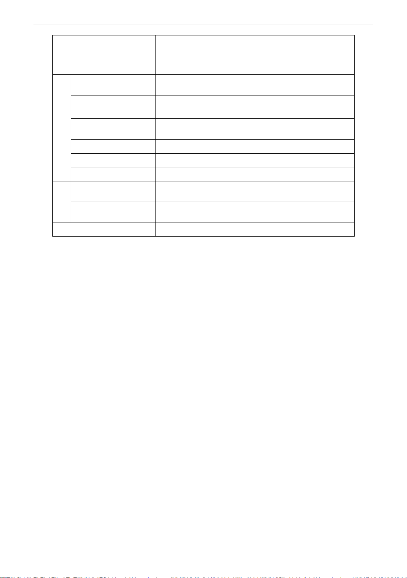
Structure
Defending grade
IP20
Cooling mode
Forced air cooling and fan controls with temperature
Mounting mode
Wall hangning or install in cabinet

3 Mechanical Installation SV600 Series User Manual
12
3 Mechanical Installation
3.1 Installation
3.1.1 Installation Environment
The installation environment is very important for the long-term maintenance of the
performance and function of the frequency inverter. Please install the inverter according to the
below Table 3-1.
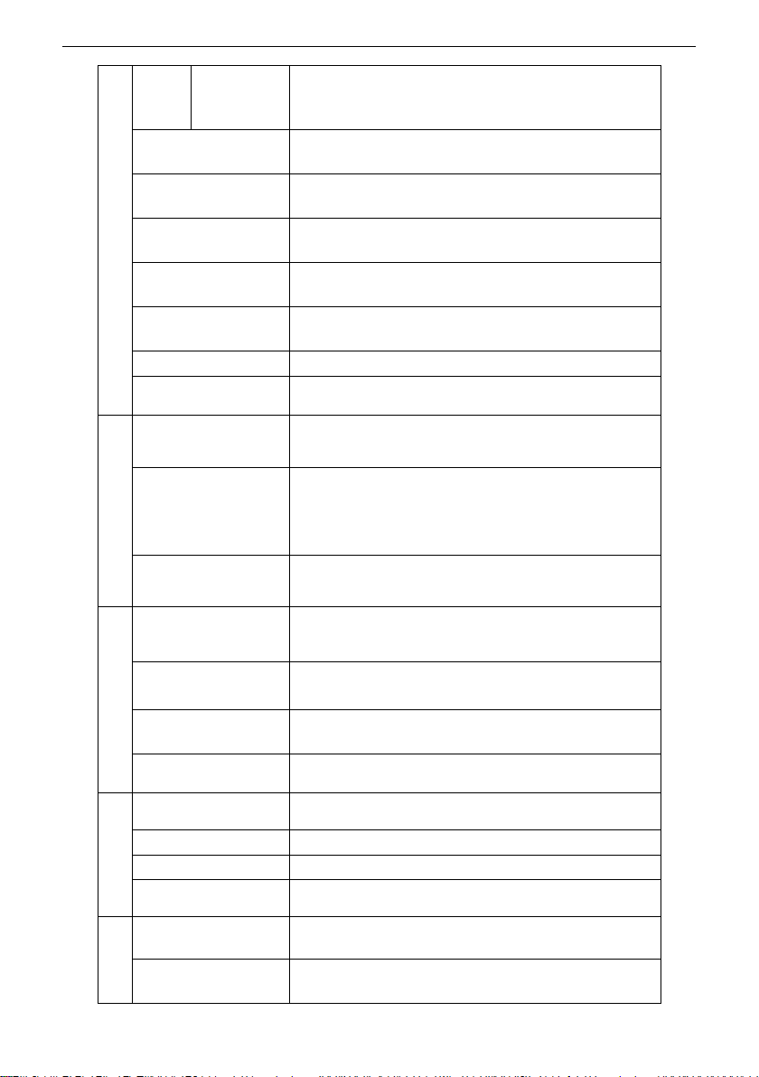
Table 3-1 Installation Environment
Item
Requirements
Installation site
Indoor
Ambient
temperature
-10 to +40 °C
In order to improve the reliability of the inverter, please use it in the place where
the temperature does not change drastically.
When using it in a closed space such as a control cabinet, please use cooling fan
or cooling air conditioner to cool it and prevent the internal temperature from exceeding
the condition temperature.
Please avoid the inverter freezing.
Humidity
95% RH or below
Please avoid condensation on the inverter.
Storage
temperature
-20 ~ + 60 °C
Environment
Please install the inverter in the following locations.
Locations free from oil mist, corrosive gases, flammable gases, dust, etc.
Locations that metal powder, oil, water and other external objects can not enter
the inverter (Do not install the inverter on flammable materials such as wood).
Location without radioactive materials and flammable materials
Place without harmful gases and liquids
Place with less salt erosion
Place without direct sunlight
Altitude
Less than 1000m, derating 1% for each 100 meters when higher than 1000m. <1>
Note 1: Please do not install transformers or other equipments around the inverter which generate
electromagnetic waves or interference, otherwise it will cause the inverter to malfunction. If you need to
install such equipment, you should install shield plate before the inverter.
Note 2: Please use cloth or paper to cover the upper portion of the frequency inverter to prevent metal
debris, oil and water from entering into the frequency inverter during installation. After finish the job, be
sure to remove the cloth or paper, and if it still covered, the ventilation will become poor and causes the
frequency inverter to abnormally heat.

SV600 Series User Manual 3 Mechanical Installation
13
3.2 Installation direction and space
3.2.1 Installation Space
The surrounding installation space and clearance should be reserved varies with the power
levels of the SV600 series inverter.
Single inverter installation
Fig. 3-1 Single inverter installation
Table 3-2 Installation clearance requirements
Power level
Dimension requirements (Unit:mm)
2.2 KW ~ 22KW
A1 ≥ 10
B1 ≥ 200
C1 ≥ 40
30 ~ 37KW
A1 ≥ 50
B1 ≥ 200
C1 ≥ 40
≥ 45 KW
A1 ≥ 50
B1 ≥ 300
C1 ≥ 40
Multi-inverter installation
The SV600 series inverter dissipates heat from the bottom to the top. When multiple inverters
work together, please install them side by side and the upper of the inverter should be aligned.
Clearance should be reserved between each inverter as shown in Fig.3-2:
Vertical upward
B1
B1
A1
(Side view)
C1
A1
(Front view)
3 Mechanical Installation SV600 Series User Manual
14
Fig. 3-2 Installation clearance of multiple inverters
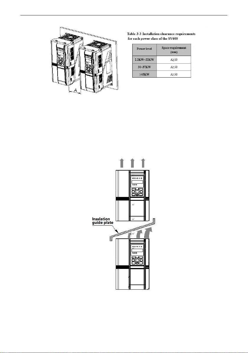
Different rows installation
If one row of inverters need to be installed above another row, please install insulation guide
plate to prevent the heat from the lower row inverters which will cause the temperature of the
upper row inverters to raise, even over-heat and overload fault occurs. Measures as shown in
Fig.3-3:
Fig.3-3 Up and down row installation
This manual suits for next models
30
Table of contents
Other SCOV Inverter manuals

Popular Inverter manuals by other brands


Lenze
Lenze SMD Series operating instructions

Salicru
Salicru EQUINOX EQX2 2001-S user manual

Toshiba
Toshiba ACE-tronics G9 ASD quick start guide

Huawei
Huawei SUN2000 Series quick guide

Go Power! Electric
Go Power! Electric GP-DC-KIT2 owner's manual

Toshiba
Toshiba TOSVERT VF-S11 Instruction manual supplement