Asko GCS29NFH User manual

Service manual
GCS29NFH - GCS30NFH
Contents
Introduction.....................................................................................................................3
Product overview............................................................................................................4
Option and settings .....................................................................................................6
Anomalies signalling ...................................................................................................8
Option and settings ........................................................................................................9
Anomalies signalling ....................................................................................................8
Components description................................................................................................11
Components values........................................................................................................13
Manual test procedure ................................................................................................17
Manual test procedure ................................................................................................18
Dismounting instructions................................................................................................19
Lower Hinge regulating.................................................................................................27
Wiring diagrams...............................................................................................................28
Exploded view.................................................................................................................30
1a EDiTION - 2014 Manufacturer reserves the possibilities to modifiy this manual without notice.
-466000288 rev.000

Service manual GCS29NFH - GCS30NFH
2

2008 01 99999 - 032999999 - 03
Week
Introduction
You are holding the service manual for the generation of touch control cooling product.
There are different types of up-right no frost freezer touch series: . The following
page presents the different versions, to help you identify the machine types.
The variants are named differently from market to market. The type designation is the most important
factor for identifying the appliances type. The type designation can be found on the label apllied
to the appliance which is located at the left lower side of the appliance.
Year Factory idProgr. nr. Model code
It should be easy to service a cooling product. It is important that you, as a service
technician, are given the conditions to be able to carry out work in an efficient and
satisfactory way. Our hope is that this service manual is a useful tool for your daily
work.
3
Service manual GCS29NFH - GCS30NFH

ON / OFF DISPLAY
FREEZER
TEMPERATURE
SETTING
SUPER
FUNCTION
PRE-ALARM
and ALARM
TEMPERATURE
DOOR OPEN
ALARM
Upright no frost freezer touch display version
ON / OFF TEMPERATURE
SETTINGS
SUPER
FUNCTION
ALARM
Upright no frost freezer touch leds version
Service manual GCS29NFH - GCS30NFH
Appliance is provided with an electronic module touch version placed inside the control panel that allow
to select various temperature positions available and within the range -16°C to -24°C.
It also allows of the fast freezing function for which the operation phase is visible by the white back light
of the related icon "SUPER" on the module. The fast freezing function can be manually deactivated by
touching again the activation switch or it will be automatically deactivated after 30 hours from when
was started. Appliance also is provided of the freezer temperature pre-alarm function and of the
temperature freezer alarm function which are described in the following paragraphs..
Appliance is provided of a touch electronic module version 5 leds placed in the control panel and allow
to select the various
temperature positions available: "MIN, MID and MAX".
It also allows of the fast freezing function for which the operation phase is visible by the white back light
of the related icon "SUPER" on the module. The fast freezing function can be manually deactivated by
touching again the activation switch or it will be automatically deactivated after 30 hours from when
was started.
Type overview
4

Service manual GCS29NFH - GCS30NFH
Type overview
No frost radiator
in the freezer
compartment
Internal view of the appliance
5

Service manual GCS29NFH - GCS30NFH
Option and settings touch display type Touch display type
IMPORTANTWARNING
Whenever the product has been lying horizontally during
transportation, it should be left to stand upright for at least six
hours before it is switched on, otherwise it may be noisy when
it is in operation.
IMPORTANT
Before plugging the appliance in, make sure that the power
supply voltage corresponds to the value shown on the product
data plate. Plug the appliance into the electricity mains supply.
The display will flash, showing the default temperature set by
the manufacturer (-16°C):
After a few seconds the display will show the actual temperature
of the refrigerator compartment. If the symbol “--” appears on
the display, the appliance is plugged in but switched off.
SWITCHINGTHE APPLIANCE ON
Switch the product on by touching the symbol for at least 0.5
seconds.
During operation, the temperature inside the refrigerator appears
on the display, which can indicate temperature values of between
+20°C and -40°C. Temperatures of over +20°C inside the
refrigerator (for example, +21°C), are indicated on the display
by the letter“H”:The temperature may be set to a value between
-16°C and -24°C.To switch off the product, touch the symbol
for 5 seconds.
SETTINGTHETEMPERATURE
The temperature may be adjusted by touching the symbol; it
may be set to a value between -16°C and -40°C.
When the refrigerator is switched on, if you touch the symbol
the set temperature value will flash on the display for 6 seconds.
To set a new temperature, touch the symbol and, while the
display is flashing, touch the same symbol repeatedly until the
desired temperature value has been reached; the new setting
will be stored after the display has stopped flashing (6 seconds).
N.B.: an option should be selected after taking into account
the frequency with which the door is opened,the temperature
of the room in which the appliance is installed and the
quantity of food contained inside the product.
For room temperatures of between 20 to 25°C, we
recommend setting the freezer temperature at -18°C.
CHECKINGTHE PROGRAMMEDTEMPERATURE
If you touch the symbol just once, the programmed temperature
will flash on the display for 6 seconds; after this the actual
temperature inside the refrigerator compartment will be displayed.
The set functions remain stored in the memory of the appliance,
even after they have been switched off or disconnected from the
electricity supply; when they are switched back on again the
temperature value set most recently will flash on the display for
6 seconds.
SUPER FUNCTION
The Super function was designed to reduce the temperature
inside the refrigerator compartment in the shortest possible time;
if you touch the text “SUPER”for at least 0.5 seconds the function
will be activated for a period of 30 hours, during which time the
text “SUPER” will be lit up in white.After this 30-hour period, the
Super function will be deactivated automatically. However, if you
wish to manually deactivate the function before the 30-hour
period has elapsed, simply touch the text “SUPER” for at least
0.5 seconds; when the function has been deactivated the text
“SUPER” will no longer be illuminated. While the appliance is
operating in Super mode, all other settings are temporarily
disabled. While the appliance is operating in Super mode, all
other freezer compartment settings are temporarily disabled.
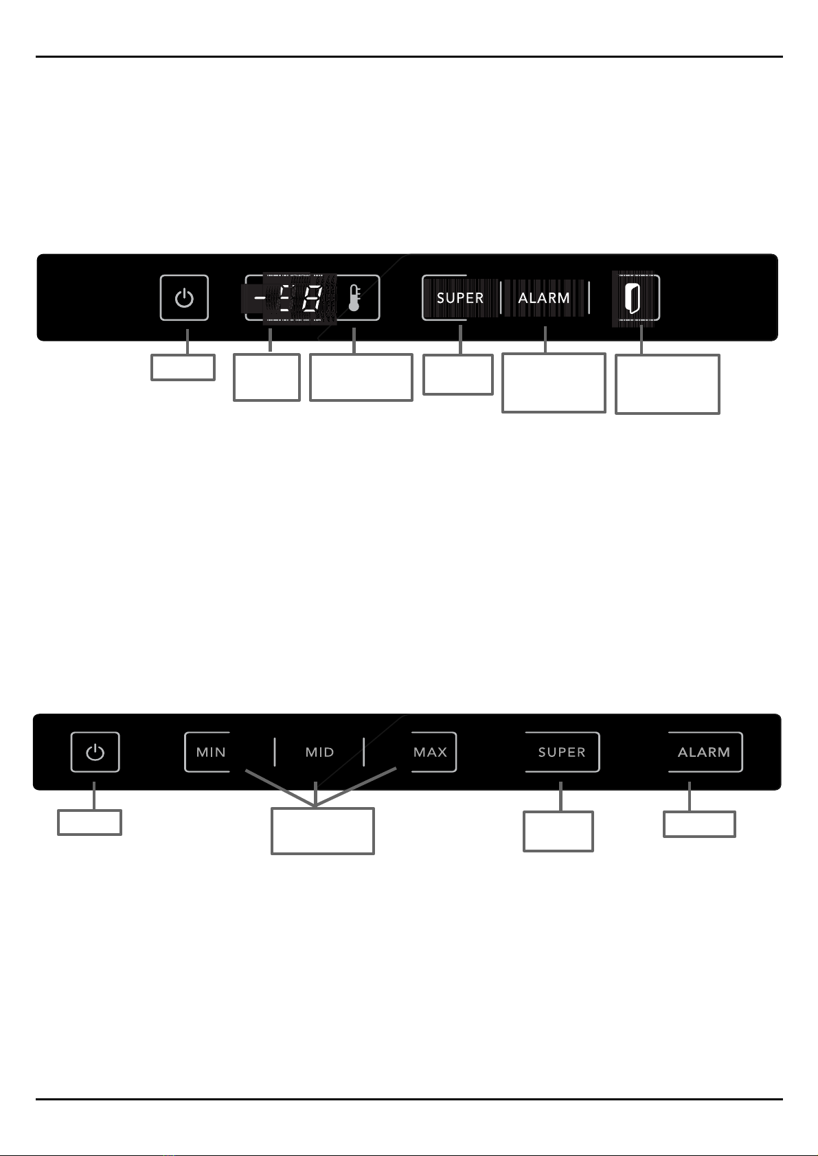
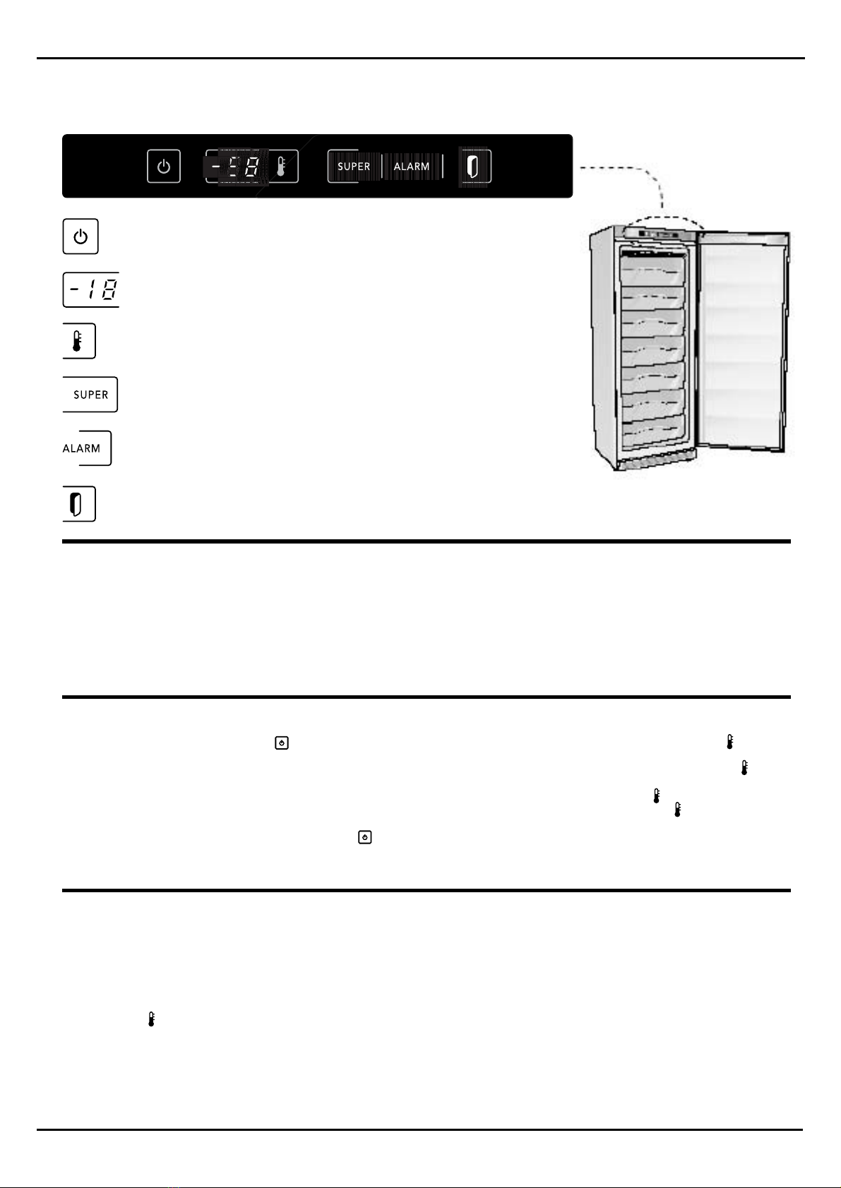
STARTINGTHE APPLIANCE - F2583NF TOUCH-DISPLAY
ON / OFF
TEMPERATURE ADJUSTMENT
SUPER FUNCTION
PREALLARME E ALLARMETEMPERATURA
DOOR OPEN ALARM
DISPLAY FREEZER
6

Touch display type
Service manual GCS29NFH - GCS30NFH
Option and settings touch display type
MALFUNCTION MANAGEMENT
If the symbol “-E” o “E-” flashes on the display, the refrigerator
will continue to operate normally for a few days but you should
contact the Technical Assistance Centre as soon as possible.
DOOR OPEN ALARM
Every time the door is opened the symbol is illuminated in
white, in a fixed manner. If the door has been open for over 2
minutes, the“DOOR OPEN”alarm is activated;it may be disabled
in one of the 2 following ways:
- if the door is closed, the audible and visible alarms are
deactivated;
- if the symbol is touched, the audible alarm is deactivated
but the illuminated white visible alarm signal willflash instead
of being a fixed light.
FREEZERTEMPERATURE ALARM
The alarm function was designed with the aim of warning the
user that, due to some external cause (for example, a power
cut, the door has been left open, etc.) the food kept in the freezer
compartment has reached a temperature higher than +1°C and
has therefore completely thawed out.
In this case, the freezer temperature alarm mode is enabled
and flashes on the display, along with the highest temperature
detected inside the compartment;the ALARM text is illuminated
in red and the audible alarm is also activated.
The display memory(maximum temperature reached) is important
because, if power is cut off and then restored, the appliance will
continue operating as normal;this could result in food which had
previously thawed out being refrozen.
PRE-ALARM MODE AND FREEZERTEMPERATURE
PRE-ALARM INDICATION
The pre-alarm mode is activated when the temperature inside
the freezer compartment reaches a value higher than -12°C (for
example, -11°C).This may occur in the following situations:
- a large amount of unfrozen food has been placed in the
freezer (see freezing modes);
- the door has been open for an extended period of time;
- the electricity supply has been cut off for a prolonged period
of time;
- the appliance has malfunctioned.
The pre-alarm mode is indicated by the temperature appearing
intermittently on the freezer display, by the flashing white ALARM
symbol and by the audible alarm. The audible alarm may be
disabled by touching the ALARM text;in this case the pre-alarm
mode indicator of the flashing temperature on the display remains
active and the ALARM text will remain lit in a fixed manner
instead of flashing.The pre-alarm mode is disabled automatically,
but only when the temperature of the freezer compartment falls
below -12°C; at this point the ALARM text will no longer be
illuminated, while the temperature will stop flashing and remain
lit in a fixed manner on the display.
STARTINGTHE APPLIANCE - MOD. F2583NFTOUCH-DISPLAY
7

Touch display type
SIGNAL ON THE DISPLAY: "-E" or "E-"
If display shows the flashing symbol "-E" or "E-" , this means that a temperature
sensor is defective:
Flashing signal "-E" indicates a defect of the defrosting sensor.
Flashing signal "E-" indicates a defect of the temperature sensor for freezer
compartment.
Solution of the problem: to verify the ohm values of the defective sensor in relation
to the values shown in the datasheet of the related sensor present inside this manual.
(if necessary replace the sensor)
Note: In this condition the appliance runs a pre-set emergency cycle that guarantee
the functioning of the appliance for some days but the defective sensor must be
replaced as soon as possible.
Checking and procedures ---
ANOMALIES MANAGING ---
(troubleshooting)
ICE FORMATION ON NO-FROST RADIATOR
POSSIBLE ANOMALIES OF FUNCTIONING FOR THE APPLIANCE
- To check the door is perfectly closed and no air could go inside the appliance
across the door gasket.
- To check the presence of the black rubber tube on the aspiration tube at the
back side of the appliance and that it is well inserted on the hole at the back
side wall of the appliance: to check that this point is well insulated.
- To check for possible obstructions of the water drain tube starting from the
point of exit for the bended tube at the back wall of the appliance: make sure
of the presence of the curve in the drain tube and that the curve is full of water
to function like a siphon to avoid air could come back inside the appliance
across the water drain tube.
- To check the electrical continuity for thermofuses by using the related
procedure attached to this manual.
- To check the right functioning for the heating element by using the related
procedure attached to this manual.
- To check the right functioning for the defrosting phase by using the related
procedure for the forced activation of the defrosting phase attached to this
manual.
Service manual GCS29NFH - GCS30NFH
Anomalies and signalling touch display type
8

IMPORTANTWARNING
Whenever the product has been lying horizontally during
transportation, it should be left to stand upright for at least six
hours before it is switched on, otherwise it may be noisy when
it is in operation.
IMPORTANT
Before plugging the appliance in, make sure that the power
supply voltage corresponds to the value shown on the product
data plate.Plug the appliance into the electricity mains supply.
SETTINGTHETEMPERATURE
3 separate temperatures may be set (indicated by the text "MIN
- MID - MAX"): the text MIN indicates a warmer temperature
inside the refrigerator compartment, the text MID indicates an
intermediate temperature inside the refrigerator compartment
and the text MAX indicates a colder temperature inside the
refrigerator compartment.
To change the settings, touch the desired symbol (MIN – MID
– MAX) for at least 0.5 seconds;the new setting will be confirmed
by the illumination in white of the selected option.
N.B.: an option should be selected after taking into account
the frequency with which the door is opened,the temperature
of the room in which the appliance is installed and the
quantity of food contained inside the product.
For room temperatures of between 20 - 25°C,we recommend
the“MID” setting.
To switch the product off, simply touch the symbol for
at least 4 seconds.
SUPER FUNCTION
The Super function was designed to reduce the temperature
inside the refrigerator compartment in the shortest possible time;
if you touch the text “SUPER”for at least 0.5 seconds the function
will be activated for a period of 30 hours, during which time the
text “SUPER” will be lit up in white.After this 30-hour period, the
Super function will be deactivated automatically. However, if you
wish to manually deactivate the function before the 30-hour
period has elapsed, simply touch the text “SUPER” for at least
0.5 seconds; when the function has been deactivated the text
“SUPER” will no longer be illuminated. While the appliance is
operating in Super mode, all other freezer compartment settings
are temporarily disabled.
SWITCHINGTHE APPLIANCE ON
Switch the product on by touching the symbol for at least 0.5
seconds; activation will be confirmed by the text “MID”, which
will light up in white.The appliance will begin operating after 30
seconds.
To switch off the product, touch the symbol for 5 seconds; at
this stage all display texts will be turned off.
ON / OFF
TEMPERATURE ADJUSTMENT
SUPER FUNCTION
ALARM FUNCTION
Service manual GCS29NFH - GCS30NFH
Option and settings touch leds type
Touch leds type
9

Touch display type
SIGNAL ON THE DISPLAY: "-E" or "E-"
If display shows the flashing symbol "-E" or "E-" , this means that a temperature
sensor is defective:
Flashing signal "-E" indicates a defect of the defrosting sensor.
Flashing signal "E-" indicates a defect of the temperature sensor for freezer
compartment.
Solution of the problem: to verify the ohm values of the defective sensor in relation
to the values shown in the datasheet of the related sensor present inside this manual.
(if necessary replace the sensor)
Note: In this condition the appliance runs a pre-set emergency cycle that guarantee
the functioning of the appliance for some days but the defective sensor must be
replaced as soon as possible.
Checking and procedures ---
ANOMALIES MANAGING ---
(troubleshooting)
ICE FORMATION ON NO-FROST RADIATOR
POSSIBLE ANOMALIES OF FUNCTIONING FOR THE APPLIANCE
- To check the door is perfectly closed and no air could go inside the appliance
across the door gasket.
- To check the presence of the black rubber tube on the aspiration tube at the
back side of the appliance and that it is well inserted on the hole at the back
side wall of the appliance: to check that this point is well insulated.
- To check for possible obstructions of the water drain tube starting from the
point of exit for the bended tube at the back wall of the appliance: make sure
of the presence of the curve in the drain tube and that the curve is full of water
to function like a siphon to avoid air could come back inside the appliance
across the water drain tube.
- To check the electrical continuity for thermofuses by using the related
procedure attached to this manual.
- To check the right functioning for the heating element by using the related
procedure attached to this manual.
- To check the right functioning for the defrosting phase by using the related
procedure for the forced activation of the defrosting phase attached to this
manual.
Service manual GCS29NFH - GCS30NFH
Anomalies and signalling touch display type
8

Service manual GCS29NFH - GCS30NFH
Components description
Not restorable thermo-fuses
This is a thermic protection device that disable
the electricity power for the heating element to
avoid the overheat in case is reached the
temperature of 72° degrees.
The device is not restorable so in case of intervention
it must be replaced with a new one because if
broken the heating element is not powered.
Motor Fan
The fan runs in parallel to the compressor
(compressor ON - motor fan ON) and it stops in
case of opening of the freezer door
(freezer compartment - no frost radiator kit)
Freezer compartment sensor
This sensor send the signal for the freezer
compartment temperature: the sensor send
the signal of alarm for the temperature of
freezer compartment too.
Not restorable thermofuses with
integrated defrosting sensor.
More recently made appliances can
use a new kind of thermo-fuse with
integrated defrosting sensor.
Defrosting end sensor
This sensor signals the end for defrosting-time
to the electronic module.
Not restorable thermofuses detail
11

Service manual GCS29NFH - GCS30NFH
SAMPLE
PHOTO
SAMPLE
PHOTO
Magnet position
At the internal upper part of the door cover
for the freezer compartment is mounted the
magnet that when move under the control
panel sends the signal to the reed to stop the
motorfan in the freezer compartment and to
start it again at the closing of the door.
Reed position
On the electronic module inside the control
panel is mounted the reed that receive the
signal from the magnet when the door
is opening: the magnet is placed inside
the upper cover of the freezer door.
The signal, when the freezer door is
opening, stops the fan in the freezer
compartment.
(reed and magnet postion)
Components description
Procedure of checking in case of malfunctioning.
To check the right functionning of the reed on the electronic module for this appliance we can proceed
as follows:
- When the door is opened, move a magnet the nearest possible to the reed position to check if the
reed detects the signal of the magnet. The symbol "opened door" on the module must switch off when
the magnet is in front of the reed and the motorfan must instead start again if compressor is running.
In case that no signals are detected will be necessary to replace the reed.
Check for the presence of the magnet inside the upper cover of the door by moving another magnet
or a metallic object the nearest possible to the magnet position on the door: in case of absence of
the
magnet inside the cover of the door no signal could be sent to the reed every time the door is closed.
12

Freezer compartment temperature sensor
FRD038 - F12496
OHM values detected at the related temperature
WARNING! Values shown at the side view are exclusively related
to the freezer compartment temperature sensor of this appliance.
Service manual GCS29NFH - GCS30NFH
Components values
(Components - datasheet)
To check the OHM value by connecting
the tester to the wires of the related
sensor on the internal connector of the
appliance
Verifying procedure
- Disconnect the appliance from main electricity supply.
- Place a thermometer the nearest possible to the head of the sensor to be checked.
- Find the point of connection of the sensor.
- after the temperature is stabilized so that thermometer and the compartment
sensor will be at the same temperature, read the temperature shown by the
thermometer previous placed near the sensor and, at the same time, check with a
tester the OHM value for the sensor detectable on the sensor wires on the jst
connector.
- Check the correct OHM value of the sensor relative to the real temperature verified
by the thermometer by following the list of OHM values in agree with the real
temperature of the sensor detected in that moment.
13

Defrosting sensor FRD127 --- F12788
OHM values detected at the related temperature
WARNING! Values shown at the side view are exclusively related
to the defrosting sensor of this appliance.
Service manual GCS29NFH - GCS30NFH
Components values
(Components - datasheet)
To check the OHM value by connecting
the tester to the wires of the related
sensor on the internal connector of the
appliance
Verifying procedure
- Disconnect the appliance from main electricity supply.
- Place a thermometer the nearest possible to the head of the sensor to be checked.
- Find the point of connection of the sensor.
- after the temperature is stabilized so that thermometer and the compartment
sensor will be at the same temperature, read the temperature shown by the
thermometer previous placed near the sensor and, at the same time, check with a
tester the OHM value for the sensor detectable on the sensor wires on the jst
connector.
- Check the correct OHM value of the sensor relative to the real temperature verified
by the thermometer by following the list of OHM values in agree with the real
temperature of the sensor detected in that moment.
14

Defrosting sensor with integrated
thermo-fuses FRD145 --- F12998
OHM values detected at the related temperature
WARNING! Values shown at the side view are exclusively related
to the defrosting sensor with integrated thermofuses of this appliance.
Service manual GCS29NFH - GCS30NFH
Components values
(Components - datasheet)
To check the OHM value by connecting
the tester to the wires of the related
sensor on the internal connector of the
appliance
Verifying procedure
- Disconnect the appliance from main electricity supply.
- Place a thermometer the nearest possible to the head of the sensor to be checked.
- Find the point of connection of the sensor.
- after the temperature is stabilized so that thermometer and the compartment
sensor will be at the same temperature, read the temperature shown by the
thermometer previous placed near the sensor and, at the same time, check with a
tester the OHM value for the sensor detectable on the sensor wires on the jst
connector.
- Check the correct OHM value of the sensor relative to the real temperature verified
by the thermometer by following the list of OHM values in agree with the real
temperature of the sensor detected in that moment.
15

Heating element and thermo-fuses
OHM values
WARNING! Values shown in this page are exclusively related to the
heating element and the thermo-fuses for this appliance.
A fast checking for the right functioning of the heating element and the thermo-fuses can be done
by detecting the OHM value at the 10 pin jst connector that is connected to the module in the control
panel:
Remove the jst connector and detect the ohm value between red and black wire as
shown in the picture above: if we find a value of about 240ohm it means that
the heating element and the thermo-fuses are correctly running. In case we do not find
any value instead, or we find a very different value, it means that the heating element
or one or both the thermo-fuses, are broken.
nr.7 black nr.10 red
Service manual GCS29NFH - GCS30NFH
Components values
(Components - datasheet)
New not restorable thermo-fuses
with integrated defrosting sensor
If we find continuity between
the two blue wires this means
the thermo-fuses is running.
Note: with thermo-fuses
connected to the heating
element on these wires will be
detected the OHM value of the
heating element
Tester
Tester
The same ohm value of the heating
element can also be detected at the
internal connector provided for
the thermo-fuses connection.
Disconnect the connector and detect
the ohm value.
Wires connected to
the heating element
Integrated defrosting
sensor wires
16

Autotest procedure to check the right functioning of the electronic module components
Touch display type procedure GCS29-30NFH CB11...../CB17.....
Manual test activation:
Service manual GCS29NFH - GCS30NFH
Manual test procedure
(Manual test procedure)
1- Switch off the electronic module by touching the button Off/Standby
2- Keep touching for 4 seconds about the button "Super": a sound of a beep will confirm the access to manual test
mode.
Are immediately shown in sequence on the digits all the numbers from 0 to 9 to verify the right functioning of the display
and the symbol "opened door" switches on if the appliance door is opened.
3- 4- Then are automatically checked the temperature sensor of the freezer compartment and the defrosting sensor:
in case of error will be shown the related message "E" provided by the data sheet in relation to the defective sensor
detected. If no errors are detected the display will remain switched off and we can
proceed to the following step.
5- Touch the symbol "fridge door", a beep sounds and confirm the right functionning for the freeser temeprature settings
button function: the led door is on.
6- Reed freezer checking:
move a magnet in front of the reed position and verify that when the magnet is in front of the reed, it will light off the
"door" symbol on the display. When the magnet is removed the symbol must switch on.
(test ok, go on to the next step)
7- Check the functions "SUPER":
touch the "SUPER" button. At the touch of the button a beep sounds and confirm the right functionning for the function.
It switches on the back light of the "SUPER" symbol. Touch it again to switch off. The led door is on.
8- Check the functions "ALARM": (red alarm led)
Touch the "ALARM" button. At the touch of the button a beep sounds and confirm the right functionning for the function.
Will light on the back red light of the "ALARM" symbol ,red alarm led is flashing, led "SUPER" is on, led door is on. (test
ok, go on to the next step)
9- Check the functions "ALARM": (white alarm led)
Touch the "ALARM" button again. At the touch of the button a beep sounds and confirm the right functionning for the
function. Will light on the back white light of the "ALARM" symbol , red alarm led is flashing, led "SUPER" is on, led
door is on . (test ok, go on to the next step)
10- Freezer door opened symbol:
Touch the "door opened symbol" button. At the touch of the button a beep sounds and confirm the right functionning
for the function. Will light on the back light of the "SUPER" symbol ,red alarm led is flashing, led door is on. (test ok,
go on to the next step)
Checking the electrical load signals sent by the electronic module to the various components:
note: in this phase the load to each component will be sent for a period of 2 minutes after that the manual test will exit
for time-out occurred.
11- Touch the button "OFF/Stand-by": the module sends the electrical load to the compressor, display shows "CO" and
the compressor start to run for about 2 minutes. Touch again the button within 2 minutes to go on to next step.
(test ok, go on to the next step)
12- Touch again the button "OFF/Stand-by": the module sends the load signal to the fan, display shows "FA" and the
fan starts to run for about 2 minutes. Touch again the button within 2 minutes to go on to next step. (test ok, go on to
the next step)
13- Touch again the button "OFF/Stand-by": the module sends the electrical load to the heating element, display shows
"HE" and the heating element starts to run for about 2 minutes. (test ok, end of autotest)
14- Touch again the button "OFF/Stand-by" for exit from manual test after 10 seconds: otherwise autotes mode
automatically exit after 120 seconds of time-out
Touch display type
reed position
17

Autotest procedure to check the right functioning of the electronic module components
Touch leds type procedure GCS29-30NFH CB11...../CB17.....Manual test activation:
Service manual GCS29NFH - GCS30NFH
Manual test procedure
(Manual test procedure) Touch leds type
reed position
1- Switch off the electronic module by touching the button Off/Standby
2- Keep touching for 4 seconds about the button "Super": a sound of a beep will confirm the access to manual test mode. Led "MIN"
will light on.
3- Touch the button "MID" symbol: At the touch of the button a beep sounds and confirm the right functionning for the function.
Led "MID" will light on. (test ok, go on to the next step)
4- Touch the button "MAX" symbol: At the touch of the button a beep sounds and confirm the right functionning for the function.
Led "MAX" will light on. (test ok, go on to the next step)
5- Touch the button "SUPER" symbol: At the touch of the button a beep sounds and confirm the right functionning for the function.
Led "SUPER" will light on. (test ok, go on to the next step)
6- Touch the button "ALARM" symbol: At the touch of the button a beep sounds and confirm the right functionning for the function.
Led "ALARM" will light on. (test ok, go on to the next step)
7- Touch the symbol OFF/Standby: it is checked the right functioning for the freezer compartment sensor: if a defect is detected it
is shown the error by simultaneous flashing of the leds "MIN, MID and MAX". otherwise, if no error is found, no light will be on and
we can touch the OFF/Standby button to go on to the next step.
8- This step will check for the right functioning of the defrosting sensor: if a defect is detected it is shown by the flashing in sequence
of the leds "MIN, MID and MAX": otherwise, if no defect is found, no light will be on and we can touch the OFF/Standby button to
go on to the next step.
Checking the right function of the buttons:
9- touch the "MIN" symbol: a beep sounds to confirm the right function of the button. (test ok, go on to the next step)
10- touch the "MID" symbol: a beep sounds to confirm the right function of the button. (test ok, go on to the next step)
11- touch the "MAX" symbol: a beep sounds to confirm the right function of the button. (test ok, go on to the next step)
12- touch the "SUPER" symbol: a beep sounds to confirm the right function of the button. (test ok, go on to the next step)
13- touch the "ALARM" symbol: a beep sounds to confirm the right function of the button. (test ok, go on to the next step)
14- Checking the right functionning for freezer door reed: close and open the freezer door: a beep sounds. (test ok, go on to the
next step)
Reed freezer checking:
Touch again the button "OFF/Standby" and within 5 seconds move a magnet in front of the reed position
a sound of a beep will confirm the reading signal for the magnet. This step ends within 10 seconds.
Checking the electrical load signals sent by the electronic module to the various components:
note: in this phase the electrical load to each component will be sent for a period of 2 minutes after that the manual test will exit
for time-out occurred.
15- Touch the button "OFF/Standby": At the touch of the button a beep sounds and confirm the right functionning for the function.
the module sends the electrical load to the compressor, "MIN" led will light on and compressor starts to run for about 2 minutes.
(test ok, go on to the next step)
16- Touch again the button "OFF/Standby": At the touch of the button a beep sounds and confirm the right functionning for the
function. the module sends the electrical load to the fan, "MID" led will light on and fan starts to run for about 2 minutes. (test ok,
go on to the next step)
17- Touch again the button "OFF/Standby": At the touch of the button a beep sounds and confirm the right functionning for the
function. the module sends the electrical load to the heating element, "MAX" led will light on and heating element starts to run for
about 2 minutes. (test ok, go on to the next step)
A further pressure on the button OFF/Standby will exit the manual test: otherwise, exit from manual
test mode automatically happens after 120 seconds of time-out.
18

Service manual GCS29NFH - GCS30NFH
Dismounting procedure
(upper door and support removing procedure)
upper door view
rotate the support in counterclockwise
sense: the door will be free and we can
remove it.
support turned lateral view support removed:
to assemble the door: place the plastic
washer on the pin before to lock the
support:
Assemble the door to the pin
and place the support on
the provided hole on the
cell: rotate the support up to lock it
19

Service manual GCS29NFH - GCS30NFH
Dismounting procedure
(no frost radiator kit area access)
To access the radiator kit it needs to remove
before all the diffuser parts starting from the
lower part up to the upper part
diffuser:1
lower part
Pull the lower panel towards
himself to make free the fixing
hooks at the lateral side.
fixing
hook
Lift the lower panel towards himself
by the lower part so to make free
the fixing hook between the diffuser
parts. (central diffuser part) .
Do the same to remove the diffuser
central part.
push at the side the fixing
hooks to make free the central
part of the upper diffuser.
fixing
hook
Fixing hooks at the upper part of the
upper diffuser immediately near the
radiator kit.
diffuser upper part: central fixing hook
fixing point between
the diffuser parts
diffuser:2
central part
diffuser:3
upper part
Radiator kit in the
freezer compartment
No frost radiator kit opening
1
2
34
20
This manual suits for next models
1
Table of contents
Other Asko Refrigerator manuals
Popular Refrigerator manuals by other brands

Ferguson Enterprises
Ferguson Enterprises Avallon AWC243TDZRH owner's manual

Haier
Haier HRQ02WNA user manual

GE
GE Profile PSS26PSTSS Dimensions and installation information

Zanussi
Zanussi ZD 17/5 RM Instruction booklet

U-Line
U-Line U-1224FZRS-00A User guide & service manual

Beko
Beko RDNE400K30ZX user manual